ProLiant DL380 Generation 2 Server Setup and Installation Guide First Edition (May 2001) Part Number 203844-001 Compaq Computer Corporation Compaq Confidential – Need to Know Required Writer: RWeaver Project: Compaq ProLiant DL380 Generation 2 Server Setup and Installation Guide Comments: Part Number: 203844-001 File Name: a-frnt.
Notice © 2001 Compaq Computer Corporation Compaq, the Compaq logo, Compaq Insight Manager, DeskPro, ProLiant, ROMPaq, TaskSmart, and SmartStart Registered in U.S. Patent and Trademark Office. CarePaq, iPaq, and Netelligent are trademarks of Compaq Information Technologies Group, L.P. in the United States and other countries. Microsoft, MS-DOS, Windows, Windows NT, Windows 2000, and Microsoft Internet Explorer are trademarks of Microsoft Corporation in the United States and other countries.
Contents About This Guide Text Conventions........................................................................................................xi Symbols in Text.........................................................................................................xii Symbols on Equipment..............................................................................................xii Important Safety Information ..........................................................................
iv Compaq ProLiant DL380 Generation 2 Server Setup and Installation Guide Server Features continued Warranties and Services........................................................................................... 1-8 Three-Year, On-Site, Limited Global Warranty ............................................... 1-9 Next Business Day Response............................................................................ 1-9 Pre-Failure Warranty .................................................................
Contents Installing Hardware Options continued Memory ................................................................................................................. 3-19 DIMM Slot Identification ............................................................................... 3-20 Maximum Memory Configuration ................................................................. 3-20 Online Spare Memory Configuration .............................................................
vi Compaq ProLiant DL380 Generation 2 Server Setup and Installation Guide Installing the Server continued Routine Maintenance ............................................................................................. 4-20 Maintenance and Service Procedures.............................................................. 4-20 Extending the Server from the Rack ............................................................... 4-20 Chapter 5 Remote Insight Lights-Out Edition (Optional) Introduction..........
Contents Server Configuration and Utilities continued Compaq Diagnostics Utility................................................................................... 7-14 Automatic Server Recovery-2 ............................................................................... 7-14 Integrated Management Log.................................................................................. 7-15 Identifying Severity Levels.............................................................................
viii Compaq ProLiant DL380 Generation 2 Server Setup and Installation Guide Regulatory Compliance Notices continued Laser Devices.......................................................................................................... A-5 Laser Safety Warnings..................................................................................... A-6 Compliance with CDRH Regulations .............................................................. A-6 Compliance with International Regulations.................
Contents LED Indicators and Switches continued Switches................................................................................................................. E-17 SCSI Interlock Disable Switch ....................................................................... E-18 NMI Switch .................................................................................................... E-18 System Maintenance Switch...........................................................................
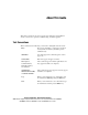
About This Guide This guide is designed to be used as step-by-step instructions for installation and as a reference for operation, troubleshooting, and future upgrades. Text Conventions This document uses the following conventions to distinguish elements of text: Keys Keys appear in boldface. A plus sign (+) between two keys indicates that they should be pressed simultaneously. USER INPUT User input appears in a different typeface and in uppercase. FILENAMES File names appear in uppercase italics.
xii Compaq ProLiant DL380 Generation 2 Server Setup and Installation Guide Symbols in Text These symbols may be found in the text of this guide. They have the following meanings. WARNING: Text set off in this manner indicates that failure to follow directions in the warning could result in bodily harm or loss of life. CAUTION: Text set off in this manner indicates that failure to follow directions could result in damage to equipment or loss of information.
About This Guide This symbol on an RJ-45 receptacle indicates a Network Interface Connection. WARNING: To reduce the risk of electrical shock, fire, or damage to the equipment, do not plug telephone or telecommunications connectors into this receptacle. This symbol indicates the presence of a hot surface or hot component. If this surface is contacted, the potential for injury exists. WARNING: To reduce the risk of injury from a hot component, allow the surface to cool before touching.
xiv Compaq ProLiant DL380 Generation 2 Server Setup and Installation Guide Getting Help If you have a problem and have exhausted the information in this guide, you can get further information and other help in the following locations. Compaq Technical Support In North America, call the Compaq Technical Phone Support Center at 1-800-OK-COMPAQ. This service is available 24 hours a day, 7 days a week. Outside North America, call the nearest Compaq Technical Support Phone Center.
About This Guide Compaq Authorized Reseller For the name of your nearest Compaq authorized reseller: ■ In the United States, call 1-800-345-1518. ■ In Canada, call 1-800-263-5868. ■ Elsewhere, refer to the Compaq website for locations and telephone numbers. Compaq Confidential – Need to Know Required Writer: RWeaver Project: Compaq ProLiant DL380 Generation 2 Server Setup and Installation Guide Comments: Part Number: 203844-001 File Name: a-frnt.
Chapter 1 Server Features The Compaq ProLiant™ DL380 Generation 2 server offers state-of-the-art performance, high availability, expanded functionality, and unsurpassed serviceability in a new space-saving 2U [8.89 cm (3.5 inches)] rack-mount chassis. This robust server supports rapid configuration deployment flexibility, making it an unbeatable computing solution for high-volume deployment requirements.
1-2 Compaq ProLiant DL380 Generation 2 Server Setup and Installation Guide ■ ROM-Based Setup Utility (RBSU) ■ Redundant hot-plug power supply (optional) ■ Redundant hot-plug fans (optional) ■ Redundant ROM ■ 133-MHz front-side bus technology ■ Two hot-plug 64-bit/66-MHz and one non-hot-plug 64-bit/33-MHz full-length PCI expansion slots ■ Front bezel system LEDs ■ Front and rear unit identification LED switches ■ MultiBay CD-ROM drive ■ Diskette drive ■ Toolless serviceable chassis ■
Server Features Industry Support Compaq delivers extensive testing and support for major server operating systems. Because Compaq provides industry-standard buses for expansion, you have access to thousands of high-performance PCI expansion boards, as well as support for SCSI devices. Customer Support Compaq servers are backed by comprehensive and flexible customer support programs.
1-4 Compaq ProLiant DL380 Generation 2 Server Setup and Installation Guide System Memory ProLiant DL380 Generation 2 servers support the following memory features: ■ 133-MHz registered SDRAM memory ■ ECC memory for single-bit memory error correction and multi-bit memory error detection ■ System memory expandable to 6 GB ■ Up to 2 GB of configurable online spare memory ■ Support for 2:1 interleaving DIMM modules Expansion Slots ProLiant DL380 Generation 2 servers provide support for peripheral co
Server Features Smart Array 5i Controller Features of the Smart Array 5i Controller include: ■ 32 MB total memory for code, transfer buffers, and read cache ■ Support for up to six internal Wide Ultra3 SCSI hot-plug hard drives in RAID 0, RAID 1, RAID 0+1, and RAID 5 ■ Support for external tape drives and external storage through the SCSI connector on the rear panel ■ Support for Compaq Universal Hot-Plug Tape ■ Easy-to-use Array Configuration Utility ■ Option ROM Configuration for Arrays ■ Pe
1-6 Compaq ProLiant DL380 Generation 2 Server Setup and Installation Guide Mass Storage Devices The ProLiant DL380 Generation 2 server can house up to eight mass storage devices (Figure 1-2). Standard configurations for drive bays include: ■ Support for up to six 1-inch, hot-plug SCSI hard drives ■ Support for one optional 1.6-inch Compaq Universal Hot-Plug Tape drive with five hot-plug SCSI hard drives installed ■ One bay occupied by a slimline 1.
Server Features ■ Two USB ports (black) ■ IDE interface for a CD-ROM drive ■ Floppy interface for a diskette drive ■ Remote Management connector (30-pin) on PCI riser cage Video Standard video integration in ProLiant DL380 Generation 2 servers includes: ■ Integrated video controller with 32-bit true color at a maximum resolution of 1280 × 1024 ■ Support for SVGA, VGA, and EGA graphics resolution ■ 8-MB SDRAM video memory ROM ROM features include: ■ Redundant ROM support ■ Software-upgradab
1-8 Compaq ProLiant DL380 Generation 2 Server Setup and Installation Guide Hot-Plug Power Supply The power supply features include: ■ 400-W hot-plug power supply ■ Support for optional redundant hot-plug power supply LED Indicators The ProLiant DL380 Generation 2 server contains several sets of LEDs that indicate the status of hardware components and settings. For a detailed explanation of LEDs, see Appendix E, “LED Indicators and Switches.
Server Features Three-Year, On-Site, Limited Global Warranty Compaq covers the cost of necessary parts and labor for on-site service during the specified warranty periods. Under the global warranty, product warranty terms at the time of purchase are honored in any country where Compaq has a service presence. This applies to customers who may purchase a product in one country, then transfer it to another.
1-10 Compaq ProLiant DL380 Generation 2 Server Setup and Installation Guide Server Configuration and Management Compaq offers an extensive set of features and optional tools to support effective server configuration and management.
Server Features ■ Compaq SmartStart for Servers CD The SmartStart CD is the recommended method for loading system software, thereby achieving a well-integrated server and ensuring maximum dependability and supportability. The SmartStart CD contains diagnostic utilities and ROMPaq tools. ■ SmartStart Diskette Builder The SmartStart Diskette Builder is a utility that uses data stored on the SmartStart CD to create support diskettes.
1-12 Compaq ProLiant DL380 Generation 2 Server Setup and Installation Guide For more detailed information about these tools and utilities, see Chapter 7, “Server Configuration and Utilities” or refer to the SmartStart documentation, the Server Setup and Management Pack, and the Documentation CD shipped with your server.
Server Features Diagnostic Tools ProLiant DL380 Generation 2 server software and firmware diagnostics tools available for your use include: ■ Power-On Self-Test ■ Diagnostics ■ Compaq ROMPaq utilities to upgrade flash ROMs ■ Automatic Server Recovery-2 For information concerning Compaq diagnostic tools, refer to the Documentation CD that ships with your server.
Chapter 2 Planning the Server Installation This chapter provides information and instructions for planning the installation of your new Compaq server. Figure 2-1 illustrates multiple ProLiant DL380 Generation 2 servers installed in a rack. Figure 2-1. ProLiant DL380 Generation 2 servers installed in a rack The following sections describe the server and site preparation required to correctly and safely install your server.
2-2 Compaq ProLiant DL380 Generation 2 Server Setup and Installation Guide ■ Server warnings and cautions ■ Server shipping contents ■ Optional installation service If you intend to deploy and configure multiple ProLiant DL380 Generation 2 servers in a single rack, consult the multiple server deployment white paper on the Compaq website: www.compaq.
Planning the Server Installation Compaq 9000 Series racks provide proper server cooling from flow-through perforations in the front and rear doors that provide 64 percent open area for ventilation. CAUTION: When using a Compaq 7000 Series rack, you must install the high airflow rack door insert [P/N 327281-B21 (42U) and P/N 157847-B21 (22U)] to provide proper front-to-back airflow and cooling.
2-4 Compaq ProLiant DL380 Generation 2 Server Setup and Installation Guide NFPA 75, 1992 Edition (code for Protection of Electronic Computer/Data Processing Equipment). For electrical power ratings on options, refer to the product’s rating label or the user documentation supplied with that option. When installing more than one server, you may need to use additional power distribution devices to safely provide power to all devices.
Planning the Server Installation The entire Rack Resource CD Kit ships with all Compaq racks. A summary of the content of each CD follows: ■ Rack Builder Pro Configuration Tool This information helps you to simulate potential Compaq rack configurations based on your input.
2-6 Compaq ProLiant DL380 Generation 2 Server Setup and Installation Guide Rack Warnings and Cautions Before installing your rack, ensure you understand the following warnings: WARNING: To reduce the risk of personal injury or equipment damage, always ensure that the rack is adequately stabilized before extending a component outside the rack. A rack may become unstable if more than one component is extended for any reason. Extend only one component at a time.
Planning the Server Installation Server Warnings and Cautions Before installing your server, ensure you understand the following warnings and cautions: WARNING: To reduce the risk of personal injury from hot surfaces, allow the drives and the internal system components to cool before touching them. WARNING: To reduce the risk of electrical shock or damage to the equipment: ■ Do not disable the power cord grounding plug. The grounding plug is an important safety feature.
2-8 Compaq ProLiant DL380 Generation 2 Server Setup and Installation Guide 1 3 2 Figure 2-2. Rack-mounting hardware Table 2-1 Rack-Mounting Hardware Item Description Standard rails with ball-bearing slides Rack template Cable management arm In addition to these supplied items, you may need the following items: ■ Application software diskettes ■ Options to be installed Optional Installation Service You may choose to have Compaq install your system.
Planning the Server Installation ■ CarePaq Installation and Start-up Services for Microsoft Windows 2000 and Windows NT operating systems ■ CarePaq Installation and Start-up and Migration Services for Novell NetWare operating system ■ CarePaq Installation and Start-up Services for Compaq Insight Manager Visit the Compaq website for detailed descriptions of these CarePaq services. This method helps ensure top performance from the start and is especially valuable for business-critical environments.
Chapter 3 Installing Hardware Options This chapter provides information and procedures for installing hardware options in ProLiant DL380 Generation 2 servers. For complete instructions, refer to the installation documentation shipped with each hardware kit.
3-2 Compaq ProLiant DL380 Generation 2 Server Setup and Installation Guide Hardware Option Procedures This chapter includes procedures for the following items: ■ Server power down ■ Access panel ■ Air baffle ■ Processors ■ Processor power modules ■ DIMMs ■ Hard drive blanks ■ Hot-plug SCSI hard drives ■ CD-ROM drive ■ CD blank ■ Compaq Universal Hot-Plug Tape drive ■ Tape drive blank ■ Redundant hot-plug fans ■ Redundant hot-plug power supply ■ PCI expansion boards Additional
Installing Hardware Options Rack Deployment Options The ProLiant DL380 Generation 2 server supports several rack-mounting options for racks not manufactured by Compaq: ■ Telco rack—a set of adjustable rack brackets that support installation in Telco racks ■ Third-party rack—a set of adjustable rack brackets that support installation and serviceability in various 48.
3-4 Compaq ProLiant DL380 Generation 2 Server Setup and Installation Guide 3. Press the front unit identification LED switch on the server front panel . Blue LEDs illuminate in the switches on the server’s front and rear panels. 4. Press the server Power On/Standby button to place the server in standby mode . When the server activates standby power mode, the system power LED turns to amber. For more information about LEDs, see Appendix E, “LED Indicators and Switches.” 1 2 Figure 3-1.
Installing Hardware Options 5. Locate the illuminated rear unit identification LED switch that identifies the server you are servicing. Figure 3-2. Locating the rear unit identification LED switch 6. Disconnect the power cords from the server. The system is now without power, and you can safely proceed with the installation of your hardware options.
3-6 Compaq ProLiant DL380 Generation 2 Server Setup and Installation Guide CAUTION: Electrostatic discharge can damage electronic components. Properly ground yourself before beginning any installation procedure. Removing the Access Panel To remove the access panel: 1. If you are installing a non-hot-plug hardware option, power down the server. See the “Powering Down the Server” section in this chapter. 2. Flip up the hood latch handle . 3.
Installing Hardware Options 4. Slide the access panel toward the rear of the unit about 1.25 cm (0.5 inches) and lift to remove the panel. Figure 3-4. Removing the access panel Installing the Access Panel After installing new hardware in your ProLiant DL380 Generation 2 server, reinstall the server access panel. To install the access panel: 1. Place the access panel on top of the server. Allow the panel to extend past the rear of the server approximately 1.25 cm (0.5 inches).
3-8 Compaq ProLiant DL380 Generation 2 Server Setup and Installation Guide 2. Slide the access panel toward the front of the unit until the panel is fully closed. Figure 3-5. Installing the access panel 3. Press the hood latch down . 4. Turn the hood latch handle one-half turn clockwise 5. Flip down the hood latch handle . . 1 2 3 Figure 3-6.
Installing Hardware Options Removing the Air Baffle A plastic air baffle directs airflow within the chassis. To perform some hardware procedures, you need to remove the air baffle. To remove the air baffle: 1. Remove the access panel. See the “Removing the Access Panel” section in this chapter. 2. Lift the air baffle. Figure 3-7. Removing the air baffle CAUTION: Always install the air baffle after completing hardware installation or maintenance procedures.
3-10 Compaq ProLiant DL380 Generation 2 Server Setup and Installation Guide Figure 3-8. Installing the air baffle 3. Install the access panel. See the “Installing the Access Panel” section in this chapter. Identifying System Board Components Use Figure 3-9 to identify the system board location and use Figure 3-10 to identify the system board connectors and components. Figure 3-9.
Installing Hardware Options 1 2 3 5 4 6 7 20 8 9 10 11 19 18 17 16 15 14 12 13 Figure 3-10.
3-12 Compaq ProLiant DL380 Generation 2 Server Setup and Installation Guide fails, the system automatically boots from processor 2 and provides a processor failure message. ProLiant DL380 Generation 2 servers use PPMs as DC-to-DC converters to provide the proper power to each processor. Each PPM must be installed in the slot adjacent to its processor.
Installing Hardware Options 4. Open the locking lever on the heatsink-retaining clip . 5. Press the base of the heatsink-retaining clip and lift the opposite end of the clip to disengage the clip from the processor socket . 6. Remove the heatsink-retaining clip . 3 2 1 Figure 3-11.
3-14 Compaq ProLiant DL380 Generation 2 Server Setup and Installation Guide 7. Remove the heatsink . CAUTION: Discard the heatsink after you remove it from the processor. The heatsink is for one-time use only; after use, the thermal interface material is degraded and does not provide proper thermal dissipation. 8. Lift the locking lever on the processor socket 9. Remove the processor . . 1 3 2 Figure 3-12.
Installing Hardware Options Installing a Processor To install a new processor: IMPORTANT: When installing a new processor, also refer to the documentation that ships with the processor. 1. Power down the server. See the “Powering Down the Server” section in this chapter. 2. Remove the access panel. See the “Removing the Access Panel” section in this chapter. 3. Remove the air baffle. See the “Removing the Air Baffle” section in this chapter. 4.
3-16 Compaq ProLiant DL380 Generation 2 Server Setup and Installation Guide CAUTION: Always use a new heatsink with thermal interface material when replacing processors. Failure to use new components may result in damage to the processor. 8. Remove the plastic cover on a new, unused heatsink to expose the thermal interface material. Figure 3-14.
Installing Hardware Options 9. Align the heatsink with the guideposts on the socket and install the heatsink . 10. Carefully install the heatsink-retaining clip . 11. Close the locking lever on the heatsink-retaining clip . 3 2 1 Figure 3-15. Installing the heatsink and heatsink-retaining clip CAUTION: PPM slots must be populated when processors are installed. If PPM slots are not populated, the system may not function correctly. 12.
3-18 Compaq ProLiant DL380 Generation 2 Server Setup and Installation Guide 3. Open the latches on the sides of the PPM slots 4. Lift the PPM out of the slot . . 1 2 1 Figure 3-16. Removing a PPM Installing a PPM To install a PPM: 1. Power down the server. See the “Powering Down the Server” section in this chapter. 2. Remove the access panel. See the “Removing the Access Panel” section in this chapter. 3. If there is an existing PPM in the PPM slot, remove the PPM.
Installing Hardware Options 5. Insert the PPM into the PPM slot . 6. Press down firmly. When the PPM seats fully in the slot, the latches close . 2 1 2 Figure 3-17. Installing a PPM 7. Install the access panel. See the “Installing the Access Panel” section in this chapter. Memory You can expand server memory by installing Compaq SDRAM. The system supports up to six 133-MHz ECC registered SDRAM DIMMs.
3-20 Compaq ProLiant DL380 Generation 2 Server Setup and Installation Guide DIMM Slot Identification Use Figure 3-18 and Table 3-2 to identify DIMM slots on the ProLiant DL380 Generation 2 server system board. The slots are numbered sequentially (1 through 6), and the paired banks are identified by the letters A, B, and C. 1 2 3 4 5 6 Figure 3-18.
Installing Hardware Options Online Spare Memory Configuration In the online spare mode, banks A and B provide standard memory functions, while bank C is configured for redundancy. DIMMs installed in bank C must be of equal or greater capacity than the largest pair of DIMMs installed in banks A or B. If any DIMMs in banks A or B exceed the limit for single-bit correctable errors, the system copies the memory contents of the failing bank to bank C; then, the system deactivates the failing bank.
3-22 Compaq ProLiant DL380 Generation 2 Server Setup and Installation Guide ■ DIMMs installed in bank C must be of equal or greater capacity than the largest pair of DIMMs installed in banks A or B. ■ RBSU must be used to configure online spare memory. Table 3-3 lists the DIMM option kit part numbers for supported DIMMs.
Installing Hardware Options 6. Insert the DIMM into the DIMM slot . 7. Press down firmly. When the DIMM seats fully in the slot, the latches close . 2 1 2 Figure 3-19. Installing a DIMM 8. Install the access panel. See the “Installing the Access Panel” section in this chapter. If you are installing DIMMs for the online spare configuration, use RBSU to configure this feature. See the “Configuring Online Spare Memory” section in Chapter 7, “Server Configuration and Utilities.
3-24 Compaq ProLiant DL380 Generation 2 Server Setup and Installation Guide To remove a hard drive blank: . 2. Pull the blank out of the drive bay . 1. Press and hold the locking button 1 2 Figure 3-20. Removing a hard drive blank NOTE: Store the hard drive blank for future use. To install a hard drive blank, simply align the blank with the empty bay and slide the blank into the bay until the locking button engages.
Installing Hardware Options SCSI ID Numbers The ProLiant DL380 Generation 2 standard configuration consists of three 2×1-inch hot-plug SCSI hard drive cages with numbered SCSI IDs: 0 through 5, indicated in Figure 3-21. IMPORTANT: Always populate hard drive bays starting with the lowest SCSI ID. 5 3 1 4 2 0 Figure 3-21.
3-26 Compaq ProLiant DL380 Generation 2 Server Setup and Installation Guide Removing Hot-Plug SCSI Hard Drives To remove hot-plug SCSI hard drives: 1. Back up all server data on the hard drive. CAUTION: Before removing a hot-plug hard drive, determine the status of the drive through the LEDs. See the “Hot-Plug SCSI Hard Drive LEDs” section in Appendix E, “LED Indicators and Switches.
Installing Hardware Options Installing Hot-Plug SCSI Hard Drives CAUTION: Before beginning this procedure, read the “Guidelines for Installing Hot-Plug SCSI Hard Drives” section in this chapter. To install hot-plug SCSI hard drives: 1. Remove the existing hard drive blank or SCSI hard drive from the bay: G If a hard drive blank is installed in the bay, see the “Removing Hard Drive Blanks” section in this chapter.
3-28 Compaq ProLiant DL380 Generation 2 Server Setup and Installation Guide Removing the CD-ROM Drive ProLiant DL380 Generation 2 servers ship standard with a thin-profile IDE CD-ROM drive in the CD MultiBay. You can remove the CD-ROM drive for security purposes. To remove the CD-ROM drive: 1. Power down the server. See the “Powering Down the Server” section in this chapter. 2. Press the ejection button . 3. Pull the CD-ROM drive out of the CD MultiBay 1 . 2 Figure 3-24.
Installing Hardware Options To install the CD blank, slide the blank into the CD MultiBay until it locks into place. Figure 3-25. Installing the CD blank Installing a Compaq Universal Hot-Plug Tape Drive The ProLiant DL380 Generation 2 server supports the Compaq Universal Hot-Plug Tape drive (AIT and DDS-4 types) for data storage and backup. When the drive is installed, only five of the six hard drive bays may be populated with SCSI hard drives. To install a Universal Hot-Plug Tape drive: 1.
3-30 Compaq ProLiant DL380 Generation 2 Server Setup and Installation Guide 2. Squeeze the middle of the tape drive blank 3. Pull to remove the blank . . 1 2 Figure 3-26. Removing the tape drive blank NOTE: Store the tape drive blank for future use. 4. Slide the Universal Hot-Plug Tape drive into the bay. Ensure the drive seats firmly into the connector on the SCSI backplane. Figure 3-27.
Installing Hardware Options Hot-Plug Components The ProLiant DL380 Generation 2 server supports hot-plug installation of fans and power supplies. The following sections contain installation procedures for these components. Installing a Redundant Hot-Plug Fan The server supports redundant hot-plug fans to provide proper airflow to the system if a primary fan fails. The ProLiant DL380 Generation 2 server airflow is divided into three zones: CPU, I/O, and power supply.
3-32 Compaq ProLiant DL380 Generation 2 Server Setup and Installation Guide Use Figure 3-28 and Table 3-4 to identify the hot-plug fans. 3 4 1 5 2 6 7 8 Figure 3-28.
Installing Hardware Options 2. Install the redundant hot-plug fan. Ensure the fan seats firmly into the connector on the system board. Figure 3-29. Installing a hot-plug fan NOTE: When performing a hot-plug fan installation, verify that the fan LED illuminates green, after you install the fan. For information about the fan LED, see the “Hot-Plug Fan LEDs” section in Appendix E, “LED Indicators and Switches.” 3. Install the access panel. See the “Installing the Access Panel” section in this chapter.
3-34 Compaq ProLiant DL380 Generation 2 Server Setup and Installation Guide To install a redundant hot-plug power supply: 1. Remove the power supply blank: a. Press the locking lever . b. Pull the blank out of the bay . 1 2 Figure 3-30. Removing a power supply blank NOTE: Store the power supply blank for future use. 2. Remove the protective cover from the connector pins on the redundant power supply. Figure 3-31.
Installing Hardware Options 3. Slide the redundant power supply into the empty bay until it locks into place. Figure 3-32. Installing a redundant hot-plug power supply NOTE: When performing a hot-plug power supply installation, verify that the power supply LED illuminates green, after you install the power supply. For information about the power supply LED, see the “Hot-Plug Power Supply LED” section in Appendix E, “LED Indicators and Switches.” 4. Connect the power cord.
3-36 Compaq ProLiant DL380 Generation 2 Server Setup and Installation Guide Identifying the Expansion Slots Use Figure 3-33 and Table 3-5 to identify the ProLiant DL380 Generation 2 server expansion slots. 3 2 1 2 3 Figure 3-33. Identifying expansion slots (rear view) Table 3-5 Expansion Slots Item Description Slot 1 – 64-bit/33-MHz 5V Slot 2 – 64-bit/66-MHz 3.3 V hot-plug capable Slot 3 – 64-bit/66-MHz 3.
Installing Hardware Options 2. Open the PCI riser cage door. Figure 3-34. Opening the PCI riser cage door 3. Lift the PCI shipping bracket and remove it from the PCI riser cage. NOTE: You can remove the PCI shipping bracket without removing the PCI riser cage. Figure 3-35. Removing the PCI shipping bracket The PCI shipping bracket is only required if you intend to ship the server with PCI expansion boards installed. If you are not installing the bracket, store it for future use.
3-38 Compaq ProLiant DL380 Generation 2 Server Setup and Installation Guide Removing the PCI Riser Cage To remove the expansion slot cover or install an expansion board in slot 1, you must remove the PCI riser cage. To remove the PCI riser cage: 1. Power down the server. See the “Powering Down the Server” section in this chapter. CAUTION: To avoid the risk of damage to your system or expansion boards, remove all AC power cords before installing or removing non-hot-plug expansion boards.
Installing Hardware Options 5. Pull up the thumbscrew knobs . 6. Loosen both thumbscrews by turning them counterclockwise . 1 1 2 2 Figure 3-36. Loosening the PCI riser cage thumbscrews (air baffle removed for clarity) 7. Lift the PCI riser cage. Figure 3-37.
3-40 Compaq ProLiant DL380 Generation 2 Server Setup and Installation Guide Removing Expansion Slot Covers CAUTION: Do not remove expansion slot covers unless you are installing an expansion card. Operating the server without an expansion card or an expansion slot cover installed results in improper airflow and improper cooling which can lead to thermal damage. To remove expansion slot covers for slots 2 and 3: 1. Remove the access panel. See the “Removing the Access Panel” section in this chapter. 2.
Installing Hardware Options 3. Open the slot release lever: a. Press and hold the release lever to unlock it b. Swing the release lever open . . 2 1 Figure 3-39. Opening the slot release lever 4. Slide the expansion slot cover out of the cage. Figure 3-40. Removing the expansion slot cover (slot 3) NOTE: Store the expansion slot cover for future use.
3-42 Compaq ProLiant DL380 Generation 2 Server Setup and Installation Guide To remove the expansion slot cover for slot 1: 1. Power down the server. See the “Powering Down the Server” section in this chapter. 2. Remove the access panel. See the “Removing the Access Panel” section in this chapter. 3. Remove the PCI riser cage. See the “Removing the PCI Riser Cage” section in this chapter. 4. Remove the thumbscrew . 5. Slide the expansion slot cover out of the cage . 2 1 Figure 3-41.
Installing Hardware Options 3. Remove the PCI shipping bracket. See the “Removing the PCI Shipping Bracket” section in this chapter. NOTE: The PCI shipping bracket is only required if you intend to ship the server with PCI expansion boards installed. 4. Remove the PCI riser cage. See the “Removing the PCI Riser Cage” section in this chapter. CAUTION: To avoid the risk of damage to your system or expansion boards, remove all AC power cords before installing or removing non-hot-plug expansion boards.
3-44 Compaq ProLiant DL380 Generation 2 Server Setup and Installation Guide 9. Install the PCI riser cage: a. Align the PCI riser cage with the chassis. b. Insert the PCI riser cage. Ensure the PCI riser cage seats firmly in the connector on the system board. Figure 3-43. Installing the PCI riser cage c. Tighten the thumbscrews . d. Lower the thumbscrew knobs by turning them one-quarter turn counter-clockwise and pressing down . 2 2 1 1 Figure 3-44.
Installing Hardware Options 10. Connect any required internal or external cables to the expansion board. Refer to the documentation that ships with your expansion board or see Chapter 6, “Server Cabling.” 11. Install the PCI shipping bracket. NOTE: The PCI shipping bracket is only required if you intend to ship the server with PCI expansion boards installed. If you are not installing the bracket, store it for future use. 12. Close the PCI riser cage door. 13. Install the access panel.
Chapter 4 Installing the Server Server Installation Guidelines Before installing your server, perform the following procedures, as necessary: ■ Select an appropriate site for your rack. For environment requirements, see the “Optimum Environment” section in Chapter 2, “Planning the Server Installation.” For information on rack planning, refer to the Rack Planning and Information Guide online document, which is on the Rack Information Library CD. ■ Unpack the server and rack-mounting hardware.
4-2 Compaq ProLiant DL380 Generation 2 Server Setup and Installation Guide IMPORTANT: If you intend to deploy and configure multiple ProLiant DL380 Generation 2 servers in a single rack, consult the multiple server deployment white paper on the Compaq website: www.compaq.com/products/servers/proliantdl380 You can choose the optional installation service from Compaq to install your rack products. See the “Optional Installation Service” section at the end of Chapter 2, “Planning the Server Installation.
Installing the Server Use the rack template to identify the required space and location for your server: 1. Identify the front side of the template. 2. Starting at the bottom of the rack, or at the top of a previously mounted component, secure the template against the front of the rack by pressing the two push tabs. Match the hole pattern on the template with the holes on the vertical rails of the rack. Figure 4-1.
4-4 Compaq ProLiant DL380 Generation 2 Server Setup and Installation Guide 3. Align the template so that the sides of the template are even with the sides of the rack. Tick marks on the vertical rails of the rack help you maintain the proper alignment. Tick marks indicate U-spaces. 4. Using a pencil, mark the locations on the rack where you insert the standard rail tabs . 5. On the rack, mark the top and bottom edges of the template helps you align a template for the next component. 2 .
Installing the Server Installing Standard Rails into the Rack To install the standard rails into the rack: 1. Complete the procedures for measuring with the template. See the “Measuring with the Template” section in this chapter. 2. Remove the left server rail from the left standard rail: a. Slide the server rail out of the front of the standard rail b. Remove the server rail . . 1 2 2 Figure 4-3. Removing the server rail from the standard rail 3.
4-6 Compaq ProLiant DL380 Generation 2 Server Setup and Installation Guide 4. Insert the front tabs of the left standard rail into the rack . 5. Press and hold the rail-locking lever to disengage the locking mechanism . 6. Compress the rail toward the front of the rack rear tabs with the rack holes. , until you can align the 1 2 3 Figure 4-4. Inserting and compressing the rail 7. Insert the rear tabs of the left standard rail into the rack is seated properly, the rail-locking lever engages .
Installing the Server 8. Repeat steps 2 through 7 for the right standard rail. Figure 4-6 shows a completed installation of the standard rails. Figure 4-6. Standard rails installed in the rack Compaq Confidential – Need to Know Required Writer: Rob Weaver Project: Compaq ProLiant DL380 Generation 2 Server Setup and Installation Guide Comments: Part Number: 203844-001 File Name: e-ch4 Installing the Server.
4-8 Compaq ProLiant DL380 Generation 2 Server Setup and Installation Guide Installing the Server Rails on the Chassis Before you can load the server into the rack, you must install the server rails on the chassis. To install the server rails: 1. Place the server on a flat, level surface. 2. Place the keyholes of the right server rail over the pins on the side of the server . 3. Slide the server rail toward the rear of the server until it locks into place .
Installing the Server To insert the server into the rack and secure it with the front panel thumbscrews: 1. Extend the slide rails forward until they lock into place. Figure 4-8. Extending the slide rails 2. Carefully align the server rails with the slide rails. 3. Ensure that the server rails are fully engaged into the plastic guides and bearings of the sliding rails on both sides, and then slowly slide the server into the rack.
4-10 Compaq ProLiant DL380 Generation 2 Server Setup and Installation Guide WARNING: To reduce the risk of personal injury, be careful when pressing the server rail-release latches and sliding the component into the rack. The sliding rails could pinch your fingertips. CAUTION: Be sure to keep the server parallel to the floor when sliding the server rails into the slide rails. Tilting the server up or down could result in damage to the rails. 4.
Installing the Server 7. Secure the server faceplate to the front of the rack by fastening the thumbscrews into the rails. Figure 4-11. Using thumbscrews to secure the positioned server in the rack 8. Before closing the rack door, tighten the thumbscrews to prevent the door from hitting any protruding thumbscrews. Installing the Cable Management Arm A triple-hinged cable management arm ships with each server. The cable management arm attaches to the server chassis and to the rear frame of the rack.
4-12 Compaq ProLiant DL380 Generation 2 Server Setup and Installation Guide 2. Attach the cable management arm to the server: a. Hook the cable management arm keyhole over the pin on the rear of the chassis . b. Press down to seat the arm on the chassis c. Fasten the thumbscrew . . 2 1 3 Figure 4-12.
Installing the Server 3. Attach the cable management arm to the rack: a. Align the unattached end of the cable management arm on the outside of the rear brace of the rack. b. Insert the hook into the rack hole . c. Press down to seat the arm in the rack . d. Fasten the thumbscrew through the rack hole into the rear of the standard rail . 2 1 3 Figure 4-13.
4-14 Compaq ProLiant DL380 Generation 2 Server Setup and Installation Guide Connecting the Power Cord and Peripheral Devices After the server has been installed in the rack, connect the power cord and peripheral devices to the connectors located on the rear panel of the server. Icons on the back of the server identify the function of each connector. WARNING: To reduce the risk of electrical shock or fire, do not plug telecommunications/telephone connectors into the NIC connectors.
Installing the Server 1 3 5 8 10 3 2 2 4 6 7 9 Figure 4-14.
4-16 Compaq ProLiant DL380 Generation 2 Server Setup and Installation Guide Power Cords Observe the following warnings when working with power cords. WARNING: The system power in the ProLiant DL380 Generation 2 server does not completely shut off with the front panel Power On/Standby button. The two positions of the button function as on and standby modes.
Installing the Server Securing the Cables to the Cable Management Arm Collect the cables connected to the rear of the server, and use the hook-and-latch strips attached to the arm to secure the cables. Figure 4-15. Cables routed in the cable management arm If you are cabling multiple ProLiant DL380 Generation 2 servers in the rack, refer to the multiple server deployment white paper at the Compaq website: www.compaq.
4-18 Compaq ProLiant DL380 Generation 2 Server Setup and Installation Guide Powering Up the Server After the cables have been connected to the server, you are ready to power up the server. To power up the server: 1. Press the Power On/Standby button. Figure 4-16. Powering up the server 2. Observe the system power LED. When the system powers up, the LED illumination changes from amber to green. After the server has successfully powered up, you can begin the configuration process.
Installing the Server 4. Press the F10 key to exit RBSU or press any other key to return to the RBSU main menu. 5. Insert the SmartStart CD or your operating system installation CD. 6. Restart the server. 7. Follow the instructions provided by SmartStart for Servers software or the operating system manufacturer. For more information about using RBSU or SmartStart to configure your server, see Chapter 7, “Server Configuration and Utilities.
4-20 Compaq ProLiant DL380 Generation 2 Server Setup and Installation Guide Routine Maintenance For information concerning routine maintenance and safety precautions, refer to the documentation that ships with your server.
Installing the Server 2. Extend the server on the standard rails until the server rail-release latches engage. Figure 4-17. Extending the server from the rack WARNING: To reduce the risk of personal injury, be careful when pressing the server rail-release latches and sliding the component into or out of the rack. The sliding rails could pinch your fingertips. 3. After performing the installation or maintenance procedure, slide the server back into the rack: a. Press the server rail-release latches. b.
Chapter 5 Remote Insight Lights-Out Edition (Optional) This chapter provides an overview of the ProLiant DL380 Generation 2 Remote Insight Lights-Out Edition option in the following sections: ■ Introduction ■ Features ■ Installation ■ Configuration and Operation For more information on Remote Insight, refer to the Compaq Remote Insight Lights-Out Edition User Guide included with the option kit. And to the Compaq website: www.compaq.com/manage/remote-lightsout.
5-2 Compaq ProLiant DL380 Generation 2 Server Setup and Installation Guide operating system. This design allows the Remote Insight board to provide remote access to any authorized network client, to send alerts, and to perform other management functions. Using any standard Web browser, you can: ■ Remotely access the console of the host server, including all text mode and graphics mode screens with full keyboard and mouse controls. ■ Remotely power up, power down, or reboot the host server.
Remote Insight Lights-Out Edition (Optional) Figure 5-2. Remote Insight board installed in the ProLiant DL380 Generation 2 server (PCI insulator removed for clarity) Compaq Confidential – Need to Know Required Writer: Rob Weaver Project: Compaq ProLiant DL380 Generation 2 Server Setup and Installation Guide Comments: Part Number: 203844-001 File Name: f-ch5 Remote Insight Lights-Out Edition.
5-4 Compaq ProLiant DL380 Generation 2 Server Setup and Installation Guide Features The Remote Insight board offers the following features: ■ Virtual graphical remote console The Remote Insight board provides embedded hardware graphical remote console capabilities that turn any standard browser into a virtual desktop, giving the user full control over the host server’s display, keyboard, and mouse.
Remote Insight Lights-Out Edition (Optional) ■ Remote Firmware Update This feature ensures that the Remote Insight board is always up-to-date with the latest firmware available from Compaq. Updates to the ROM code on the Remote Insight board are accomplished through the browser interface. ■ Integration with Compaq Insight Manager and Compaq Insight Manager XE 2.0 and Newer The Remote Insight board provides full integration with Compaq Insight Manager and Compaq Insight Manager XE 2.
5-6 Compaq ProLiant DL380 Generation 2 Server Setup and Installation Guide G Application launch task In Compaq Insight Manager XE 2.0 and newer, an application launch task can be set up to start the Group Administration Utility on all the Remote Insight boards listed on the device query page. The application launch can be executed on demand or scheduled to run automatically at a certain date and time.
Remote Insight Lights-Out Edition (Optional) ■ User administration and security The Remote Insight supports up to 12 users with customizable access rights, login names, client IP address restrictions, and advanced password encryption. A user can have supervisor status with the ability to create, modify, or delete other users. Non-supervisor users can be denied access to the Remote Insight login, to the server’s Remote Console, and to the remote reboot features of the Remote Insight board.
5-8 Compaq ProLiant DL380 Generation 2 Server Setup and Installation Guide ■ Internal Remote Management Connectors Some ProLiant servers provide integrated 16-pin or 30-pin Remote Management connectors and an interface cable that directly transmit keyboard, mouse, and power signals to the Remote Insight board. This internal cable eliminates the need for the external loopback cable and Remote Insight AC adapter.
Remote Insight Lights-Out Edition (Optional) ■ ROM-Based Configuration Utility (F8) This software is a versatile, system-independent ROM-based configuration utility that enables fast and easy setup of the Remote Insight board. ■ Single mouse cursor mode The Remote Insight board can be set to use single cursor mode in remote console (requires Java 1.3.0_01 VM). ■ Enabled Pocket PC access Firmware version 2.
5-10 Compaq ProLiant DL380 Generation 2 Server Setup and Installation Guide 4. Remove the PCI riser cage. See the “Removing the PCI Riser Cage” section in Chapter 3, “Installing Hardware Options.” 5. Install the Remote Insight board in expansion slot 1 on the PCI riser cage. See the “Installing an Expansion Board” section in Chapter 3, “Installing Hardware Options.” 6. Locate the Remote Insight interface cable that ships standard with the ProLiant DL380 Generation 2 server.
Remote Insight Lights-Out Edition (Optional) 12. Locate the Remote Insight external connectors on the rear of the server. 3 2 1 2 3 4 Figure 5-4. Remote Insight external connectors Table 5-1 Remote Insight External Connectors Item Description RJ-45 connector Keyboard/mouse connector * Video connector AC adapter connector * Note: * Do not use the keyboard/mouse loopback cable when the internal Remote Insight interface cable is installed.
5-12 Compaq ProLiant DL380 Generation 2 Server Setup and Installation Guide 14. Connect your video cable to the external video connector on the Remote Insight board. Figure 5-5. Connecting the video cable to the Remote Insight external video connector 15. Connect your LAN cable to the external RJ-45 connector on the Remote Insight board. Figure 5-6.
Remote Insight Lights-Out Edition (Optional) 16. Power up the server. See the “Powering Up the Server” section in Chapter 4, “Installing the Server.” Configuration and Operation For specific instruction on configuring and operating the Remote Insight board, refer to the Compaq Remote Insight Lights-Out Edition User Guide included with the option kit. For the latest ROM updates to the Remote Insight board, visit the Compaq website: www.compaq.
Chapter 6 Server Cabling This chapter provides guidelines that help you make informed decisions about cabling your server and hardware options to optimize performance. For complete and comprehensive information, use this chapter along with the technical information on the hardware installation and configuration poster and the labels attached to the inside of the server access panel.
6-2 Compaq ProLiant DL380 Generation 2 Server Setup and Installation Guide Internal Cabling The following sections explain internal cabling configurations for the ProLiant DL380 Generation 2 server. Hot-Plug SCSI Hard Drives The ProLiant DL380 Generation 2 server standard configuration for internal SCSI hard drives requires only one cable, because all SCSI hard drives connect directly to the SCSI backplane. A short SCSI cable connects the SCSI backplane to the system board at SCSI port 2 (Figure 6-1).
Server Cabling CD MultiBay Cable The CD MultiBay cable connects the CD-ROM drive to the SCSI backplane. The cable connects to the CD MultiBay board and connects to the CD MultiBay connector on the SCSI backplane (Figure 6-2). Figure 6-2. CD MultiBay cable connected to SCSI backplane Diskette Interface Cable The diskette interface cable connects the diskette drive to the SCSI backplane.
6-4 Compaq ProLiant DL380 Generation 2 Server Setup and Installation Guide The ProLiant DL380 Generation 2 server does not support any additional cabling for internal mass storage devices. To add mass storage devices, see the “External Cabling” section in this chapter. System Cables The server contains two system cables (Figure 6-4): ■ An LED/CD-ROM drive system cable connects the LED/CD-ROM drive connector on the SCSI backplane to the LED/CD-ROM drive connector on the system board .
Server Cabling Power Button/LED Cable The power button/LED cable connects the power button/LED board to the SCSI backplane (Figure 6-5). Figure 6-5. Power button/LED cable connected to SCSI backplane PCI Hot Plug Backplane Cable The ProLiant DL380 Generation 2 server contains a PCI Hot Plug backplane that is part of the PCI riser cage. The PCI Hot Plug backplane provides hot-plug capability to two expansion slots. A ribbon cable connects the PCI Hot Plug backplane to the riser board (Figure 6-6).
6-6 Compaq ProLiant DL380 Generation 2 Server Setup and Installation Guide Power Cabling The ProLiant DL380 Generation 2 server contains three internal power cables (Figure 6-7): ■ A system power cable connecting the power converter module to the system power connector on the system board ■ A power supply signal cable connecting the power converter module to the power supply signal connector on the system board ■ A SCSI power cable connecting the power converter module to the SCSI power connector on
Server Cabling ProLiant DL380 Generation 2 Server Options Additional internal cabling is required only when you install optional expansion boards, such as the Remote Insight Lights-Out Edition board or an internal PCI-based Smart Array controller. Remote Insight Lights-Out Edition Option The PCI riser cage provides a connector for the Remote Insight interface cable.
6-8 Compaq ProLiant DL380 Generation 2 Server Setup and Installation Guide External Cabling The following sections describe cabling for peripheral devices and external mass storage devices supported by the ProLiant DL380 Generation 2 server. Power Cord and Peripheral Device Cabling Rear panel cabling on the ProLiant DL380 Generation 2 server must always be connected and disconnected in a specific sequence.
Server Cabling SCSI Cabling Guidelines The following guidelines are an overview for first-time cable connections and installation in the ProLiant DL380 Generation 2 server. To determine the server cabling needs for your specific application: 1. Determine whether cabling needs are for primary storage (hard drive) or for secondary storage (tape drive or CD-ROM drive). 2. Identify the controller type. 3. Identify the drive types to be used: G SCSI hard drives G Tape drives G CD-ROM storage drives 4.
Chapter 7 Server Configuration and Utilities This chapter provides information about the following utilities and support tools: ■ ROM-Based Setup Utility (RBSU) ■ Redundant ROM Support ■ ROMPaq Utility ■ Smart Components for Remote ROM Flash ■ ROM Legacy USB Support ■ Compaq SmartStart for Servers CD ■ SmartStart Diskette Builder ■ SmartStart Scripting Toolkit ■ Compaq Insight Manager XE ■ Compaq Diagnostics Utility ■ Automatic Server Recovery (ASR-2) ■ Integrated Management Log (I
7-2 Compaq ProLiant DL380 Generation 2 Server Setup and Installation Guide ROM-Based Setup Utility RBSU replaces the System Configuration Utility used in previous systems.
Server Configuration and Utilities RBSU is divided into a series of menu selections designed to configure specific areas of the system. The primary menus are as follows: ■ System Options ■ IPL Device Boot Order ■ PCI Devices ■ Boot Controller Order ■ Date and Time ■ Server Passwords ■ Automatic Server Recovery ■ Server Asset Tags ■ Advanced Options ■ Utility Language Table 7-1 at the end of this section contains the default settings for options in primary RBSU menus.
7-4 Compaq ProLiant DL380 Generation 2 Server Setup and Installation Guide Embedded NIC 1 PXE Support enables you to enable or disable PXE support for NIC 1. Embedded NIC 2 PXE Support enables you to enable or disable PXE support for NIC 2. Diskette Write Control enables you to configure the write control of the diskette drive. The options are read and write or read only. Diskette Boot Control enables you to have the system boot from the diskette drive.
Server Configuration and Utilities Network Server Mode enables the user to disable or enable the system’s capability to boot with a locked keyboard or without a keyboard. To unlock the keyboard, enter the Power-On Password. QuickLock enables you to lock your keyboard and prompts you for the power-on password to unlock the keyboard. IMPORTANT: If you forget your password, you can clear all passwords by resetting the system maintenance switch. See “Switches” in Appendix E, “LED Indicators and Switches.
7-6 Compaq ProLiant DL380 Generation 2 Server Setup and Installation Guide Advanced Memory Protection enables you to choose one of the following memory modes: ■ Standard ECC sets the system to use the standard paired DIMM configuration. ■ Online Spare support tests the DIMM configuration and sets the system to use the online spare memory feature. Utility Language The Utility Language enables you to set the display language for RBSU.
Server Configuration and Utilities Table 7-1 RBSU Default Settings continued Menu/Option Default Setting NUMLOCK Power-On State Enabled Embedded NIC 1 PXE Support Enabled Embedded NIC 2 PXE Support Disabled Diskette Read/Write Control Enabled Diskette Boot Control Enabled IPL Device Boot Order IPL Device Boot Order Enabled Server Passwords Administrator Password Disabled Power-On Password Disabled Network Server Mode Disabled QuickLock Disabled Automatic Server Recovery Automatic Serv
7-8 Compaq ProLiant DL380 Generation 2 Server Setup and Installation Guide Configuring Online Spare Memory To configure online spare memory: 1. Install the required DIMMs. See the “Memory” and “Installing DIMMs” sections in Chapter 3, “Installing Hardware Options.” IMPORTANT: If your DIMM configuration does not meet the criteria for online spare memory support, the system does not allow you to configure this feature. 2.
Server Configuration and Utilities Access to Redundant ROM Settings To access the redundant ROM: 1. Access RBSU by pressing the F9 key during power up when the prompt displays in the lower right corner of the screen. 2. Select Advanced Options. 3. Select Redundant ROM. 4. Select one of the ROM banks as the system ROM. 5. Press the Enter key. 6. Press the Esc key to exit the current menu or press the F10 key to exit RBSU. 7. Restart the server.
7-10 Compaq ProLiant DL380 Generation 2 Server Setup and Installation Guide Smart Components for Remote ROM Flash Smart Components for Remote ROM Flash enables Microsoft Windows NT 4.0 and Windows 2000 operating system administrators to efficiently upgrade and manage system and array controller ROMs.
Server Configuration and Utilities To determine whether an operating system supports a particular feature, visit the Compaq FTP site: ftp.compaq.com/pub/products/servers/os%20feature%20matrix%20103000.pdf Compaq SmartStart for Servers CD The SmartStart CD is the recommended method for loading system software, thereby achieving a well-integrated server and ensuring maximum dependability and supportability. The SmartStart CD contains diagnostic utilities and ROMPaq tools.
7-12 Compaq ProLiant DL380 Generation 2 Server Setup and Installation Guide SmartStart Diskette Builder The SmartStart Diskette Builder is a utility that uses data stored on the SmartStart CD to create support diskettes. You can create support diskettes for specific configuration needs or for software that cannot be used directly from the SmartStart CD.
Server Configuration and Utilities server configuration to a scripted file. You can edit and modify settings in the scripted file at the subset level. For example, you can change ASR-2 settings without having to change settings for boot controller order. For more information, refer to the Compaq SmartStart Scripting Toolkit User Guide. Compaq Insight Manager XE Compaq Insight Manager XE is the Compaq application for easily managing network devices.
7-14 Compaq ProLiant DL380 Generation 2 Server Setup and Installation Guide ■ Asset Management—Compaq Insight Manager XE enables you to export asset information from the Compaq Insight Manager XE database to leading database and spreadsheet applications, making asset management easier than ever. ■ Remote Management—Compaq Insight Manager XE enables you to manage in-band or out-of-band devices online or offline from anywhere.
Server Configuration and Utilities Integrated Management Log The IML records hundreds of events and stores them in an easy-to-view form. The IML time-stamps each event with one-minute granularity.
7-16 Compaq ProLiant DL380 Generation 2 Server Setup and Installation Guide Use the instructions in the following section to view and print the event list from within Compaq Insight Manager XE. You can also mark a critical or caution event as repaired after the affected component has been replaced. For example, when a failed fan is replaced, you can mark the event as repaired, which lowers the severity of the event. NOTE: You can only view the list from the Recovery/Integrated Management Log screen.
Server Configuration and Utilities Refer to the Compaq Management CD for information on installing and running the Survey Utility. After you run the Survey Utility, you can view the IML by loading the output of the utility (typically called SURVEY.TXT) into a text viewer such as Microsoft Notepad. The event list follows the system slot information. After you open the text file, you can print it using the print feature of the viewer.
Chapter 8 PCI Hot Plug Technology The ProLiant DL380 Generation 2 server supports PCI Hot Plug technology. This chapter provides a brief discussion of PCI Hot Plug technology. For more information, refer to documentation that ships with your server.
8-2 Compaq ProLiant DL380 Generation 2 Server Setup and Installation Guide PCI Hot Plug Technology With PCI Hot Plug capabilities, you can remove and add PCI expansion boards without powering down the server, but you must use the proper procedure. For procedures, see the “PCI Hot Plug LEDs and Button” and “Installing Hot-Plug Expansion Boards” sections in this chapter. If you are installing a PCI expansion board, plan the SCSI configuration before installing the board.
PCI Hot Plug Technology For information about procedures using utilities and PCI Hot Plug applications, see the “PCI Hot Plug Application Support” section in this chapter. PCI Hot Plug Feature The PCI Hot Plug feature, standard in the ProLiant DL380 Generation 2 server, enables you to remove, replace, upgrade, and add PCI expansion boards without powering down the server. Any expansion board can be placed in a PCI Hot Plug slot.
8-4 Compaq ProLiant DL380 Generation 2 Server Setup and Installation Guide Use the following figures and tables to identify PCI Hot Plug components and slot conditions: 1 2 3 4 3 2 Figure 8-1.
PCI Hot Plug Technology 1 2 3 Figure 8-2. Internal PCI Hot Plug LEDs and button Table 8-2 Internal PCI Hot Plug LEDs and Button Item Description Power LED (green) PCI Hot Plug button Fault LED (amber) Compaq Confidential – Need to Know Required Writer: Rob Weaver Project: Compaq ProLiant DL380 Generation 2 Server Setup and Installation Guide Comments: Part Number: 203844-001 File Name: i-ch8 PCI Hot Plug Technology.
8-6 Compaq ProLiant DL380 Generation 2 Server Setup and Installation Guide Table 8-3 PCI Hot Plug LED Status Combinations LED Green Amber Green Amber Green Amber Power Status OK to Open Slot Status On No Power is currently applied to the slot. Do NOT open the slot release lever. The slot is functioning normally. No Power is currently applied to this slot, but the slot needs ATTENTION for a possible problem with the slot, board, or driver. Do NOT open the slot release lever.
PCI Hot Plug Technology Table 8-3 PCI Hot Plug LED Status Combinations continued LED Green Amber Green Amber Power Status OK to Open Slot Status Off No Power to this slot is turned off, but this slot needs ATTENTION. There may be a problem with the slot, expansion board, or driver. Follow these steps: On Off Off Yes 1. Open the slot release lever (the amber LED turns off). 2. Remove, replace, or install the expansion board. 3. Connect the cables to the expansion board. 4.
8-8 Compaq ProLiant DL380 Generation 2 Server Setup and Installation Guide Installing Hot-Plug Expansion Boards Before installing expansion boards in the hot-plug expansion slots, you must install an operating system that supports PCI Hot Plug technology. To install an operating system, see Chapter 4, “Installing the Server.” CAUTION: Do not attempt a PCI Hot Plug procedure if your operating system does not provide PCI Hot Plug support, or if you do not have the appropriate device drivers installed.
PCI Hot Plug Technology 4. Remove the PCI shipping bracket. See the “Removing the PCI Shipping Bracket” section in Chapter 3, “Installing Hardware Options.” NOTE: The PCI shipping bracket is only required if you intend to ship the server with PCI expansion boards installed. 5. Identify the hot-plug expansion slot you want to populate and the PCI Hot Plug button that manages it. See Figure 8-2.
8-10 Compaq ProLiant DL380 Generation 2 Server Setup and Installation Guide 9. Align the expansion board with the hot-plug expansion slot, and slide the expansion board into the slot. Figure 8-5. Inserting an expansion board in the hot-plug expansion slot 10. Connect any required cables to the PCI expansion board. Refer to the documentation that ships with your expansion board or see Chapter 6, “Server Cabling.” 11. Close the slot release lever. 12. Press the PCI Hot Plug button. 13.
PCI Hot Plug Technology NOTE: For information about using a PCI Hot Plug utility for installations with system drivers, refer to the software documentation shipped with your server and to documentation provided by the manufacturer of your operating system. PCI Hot Plug Application Support In partnerships with Microsoft, Novell, and SCO, Compaq has developed software support implementations for each operating system.
8-12 Compaq ProLiant DL380 Generation 2 Server Setup and Installation Guide The Windows NT PCI Hot Plug utility screen is divided into three sections: ■ Top—This area enables you to connect to a remote computer by typing the machine name in the combo box, selecting a machine from the combo box, or using Browse to bring up a selection dialog. Refresh refreshes the PCI Hot Plug information for the current machine.
PCI Hot Plug Technology Replacing an Expansion Board To replace an expansion board: 1. In the PCI Hot Plug Utility, turn off the power to the required slot by selecting it and clicking the power button. 2. Remove the existing expansion board: a. Disconnect cables, if necessary. b. Open the slot release lever. c. Remove the expansion board from the slot. 3. Install the new expansion board: a. Install the new expansion board in the slot. b. Attach the appropriate cables. c. Close the expansion slot lever. 4.
8-14 Compaq ProLiant DL380 Generation 2 Server Setup and Installation Guide Novell NetWare Configuration Manager Console The Novell NetWare Configuration Manager Console (NCMCON) user interface enables you to view status information on PCI slots and control features, such as removing and adding PCI Hot Plug expansion boards all from one focal point. Navigating NCMCON Menus The NCMCON interface constantly retrieves and displays the status of all of the slots.
PCI Hot Plug Technology Viewing Slot Detail Information To view slot detail information: 1. From the Main menu, highlight the slot and expansion board information to be viewed. 2. Press the Enter key. 3. Select Slot Detail Information from the Slot Options menu. Removing an Expansion Board To remove an expansion board: 1. From the Main menu, highlight the slot and expansion board to be removed. 2. Press the Enter key to go to the Slot Options menu. 3.
8-16 Compaq ProLiant DL380 Generation 2 Server Setup and Installation Guide 5. When the new expansion board is detected, NCMCON automatically asks if you want to configure and apply power to the slot. G If you answer “Yes,” power is applied to the slot, the green LED illuminates, and the status of the slot on the console changes to READY. G If you answer “No,” the console status does not change. 6. Press the Enter key to go to the Slot Options menu. 7.
PCI Hot Plug Technology Novell NetWare Operating System Messages The Novell NetWare operating system uses the following list of messages to indicate errors during PCI Hot Plug operations: Adapter Not Same—The expansion board is not the same as the expansion board being replaced. The hot-plug replacement cannot continue. Card Functioning—The expansion board in the slot is currently functioning. The add/replace procedure is ignored. Driver in Use—The expansion board is currently in use.
Appendix A Regulatory Compliance Notices Regulatory Compliance Identification Numbers For the purpose of regulatory compliance certifications and identification, your Compaq ProLiant DL380 Generation 2 server is assigned a Compaq series number. The Compaq series number for this product is: Series ES1016. The Compaq ProLiant DL380 Generation 2 server series number can be found on the product label, along with the required approval markings and information.
A-2 Compaq ProLiant DL380 Generation 2 Server Setup and Installation Guide in both classes to bear a label indicating the interference potential of the device as well as additional operating instructions for the user. The rating label on the device shows which class (A or B) the equipment falls into. Class B devices have an FCC logo or FCC ID on the label. Class A devices do not have an FCC logo or FCC ID on the label.
Regulatory Compliance Notices Declaration of Conformity for Products Marked with the FCC Logo – United States Only This device complies with Part 15 of the FCC Rules. Operation is subject to the following two conditions: (1) this device may not cause harmful interference, and (2) this device must accept any interference received, including interference that may cause undesired operation. For questions regarding your product, contact: Compaq Computer Corporation P. O.
A-4 Compaq ProLiant DL380 Generation 2 Server Setup and Installation Guide Canadian Notice (Avis Canadien) Class A Equipment This Class A digital apparatus meets all requirements of the Canadian Interference-Causing Equipment Regulations. Cet appareil numérique de la classe A respecte toutes les exigences du Règlement sur le matériel brouilleur du Canada. Class B Equipment This Class B digital apparatus meets all requirements of the Canadian Interference-Causing Equipment Regulations.
Regulatory Compliance Notices Japanese Notice Taiwanese Notice Laser Devices All Compaq systems equipped with a laser device comply with safety standards, including International Electrotechnical Commission (IEC) 825. With specific regard to the laser, the equipment complies with laser product performance standards set by government agencies as a Class 1 laser product. The product does not emit hazardous light; the beam is totally enclosed during all modes of customer operation and maintenance.
A-6 Compaq ProLiant DL380 Generation 2 Server Setup and Installation Guide Laser Safety Warnings WARNING: To reduce the risk of exposure to hazardous radiation: ■ Do not try to open the laser device enclosure. There are no user-serviceable components inside. ■ Do not operate controls, make adjustments, or perform procedures to the laser device other than those specified herein. ■ Allow only Compaq authorized service technicians to repair the laser device.
Regulatory Compliance Notices Laser Information Laser Type Semiconductor GaAIAs Wave Length 780 nm +/- 35 nm Divergence Angle 53.5 degrees +/- 0.5 degrees Output Power Less than 0.2 mW or 10,869 W·m-2 sr-1 Polarization Circular 0.25 Numerical Aperture 0.45 inches +/- 0.04 inches Battery Replacement Notice Your computer is provided with an internal lithium battery or battery pack. There is a danger of explosion and risk of personal injury if the battery is incorrectly replaced or mistreated.
A-8 Compaq ProLiant DL380 Generation 2 Server Setup and Installation Guide Power Cords The power cord set included in your server meets the requirements for use in the country where you purchased your server. If you use this server in another country, you should purchase a power cord that is approved for use in that country. The power cord must be rated for the product and for the voltage and current marked on the product's electrical ratings label.
Appendix B Electrostatic Discharge To prevent damaging the system, be aware of the precautions you need to follow when setting up the system or handling parts. A discharge of static electricity from a finger or other conductor may damage system boards or other static-sensitive devices. This type of damage may reduce the life expectancy of the device.
B-2 Compaq ProLiant DL380 Generation 2 Server Setup and Installation Guide Grounding Methods There are several methods for grounding. Use one or more of the following methods when handling or installing electrostatic-sensitive parts: ■ Use a wrist strap connected by a ground cord to a grounded workstation or computer chassis. Wrist straps are flexible straps with a minimum of 1 megohm ± 10 percent resistance in the ground cords. To provide proper ground, wear the strap snug against the skin.
Appendix C Server Error Messages Use POST error messages to assist in troubleshooting and performing basic diagnostic functions in your Compaq ProLiant DL380 Generation 2 server. For a complete listing of error messages and other troubleshooting information, refer to the Compaq Servers Troubleshooting Guide provided on your Documentation CD or online at the Compaq support website: www.compaq.com/support/reference/index.html Table C-1 contains new and unique error messages that arise during the POST.
Appendix D Troubleshooting This appendix provides specific troubleshooting information for your Compaq ProLiant DL380 Generation 2 server. Use it to find details about server startup and operation errors. For a list of new server error messages specific to this server, see Appendix C, “Server Error Messages.” For information on LEDs and switches specific to your server, see Appendix E, “LED Indicators and Switches.
D-2 Compaq ProLiant DL380 Generation 2 Server Setup and Installation Guide This appendix includes the following topics: ■ When the Server Does Not Start You are provided with initial instructions on what to try and where to go for help for the most common problems encountered during initial POST. A successful startup requires the server to complete this test each time you power up, before the server can load the operating system and start running software applications.
Troubleshooting When the Server Does Not Start This section provides systematic instructions on what to try and where to go for help for the most common problems encountered during initial POST. The server must first complete this test each time you power up, before it can load the operating system and start running software applications. WARNING: There is a risk of personal injury from hazardous energy levels.
D-4 Compaq ProLiant DL380 Generation 2 Server Setup and Installation Guide G “Automatic Server Recovery-2” G “System Short Circuit” for other reasons for repeatedly rebooting 7. Restart the server. IMPORTANT: If the server does not restart, proceed to the following section, “Diagnostic Steps.” 8. Check the server for the following normal power-up sequence to verify that your system meets the minimal hardware requirements and is powered up during normal operations: a.
Troubleshooting Diagnostic Steps If your server does not power up, or powers up but does not complete POST, answer the questions in Table D-1 to determine appropriate actions based on the symptoms observed. Figure D-1 is a visual representation of the diagnostic steps in flowchart format. According to the answers you give, you are directed to the appropriate table in the section that immediately follows.
D-6 Compaq ProLiant DL380 Generation 2 Server Setup and Installation Guide Is the system power LED amber? No See Table D-2. Yes Is the system power LED green? No See Table D-3. Yes Is the external health LED green? No See Table D-4. Yes Is the internal health LED green? No See Table D-5. Yes Is the monitor displaying text? No See Table D-6. Yes Use POST messages to diagnose the problem. Figure D-1.
Troubleshooting Table D-2 Is the System Power LED Amber? Answer Possible Reasons Possible Solutions No The server is not connected to AC power, or no AC power is available. Ensure that the power cord is connected to the power supply. A power supply problem exists. The power supply may not be inserted properly, it may have a damaged connector, or it may have failed. Ensure that the power supply is undamaged, and the power supply is fully seated.
D-8 Compaq ProLiant DL380 Generation 2 Server Setup and Installation Guide Table D-3 Is the System Power LED Green? Answer Possible Reasons Possible Solutions No Power On/Standby button has not been pressed firmly. Firmly press the Power On/Standby button. A power supply problem exists. The power supply may not be inserted properly, it may have a damaged connector, or it may have failed. Ensure that the power supply is undamaged, and the power supply is fully seated.
Troubleshooting Table D-5 Is the Internal Health LED Green? Answer Possible Reasons Possible Solutions No, it is amber A processor is in pre-failure condition. Use amber failure LEDs to identify: A DIMM is in pre-failure condition. ■ Missing components One memory bank is valid, but another bank is missing a DIMM. ■ Degraded components ■ Failed components One memory bank is valid, but another bank has mismatched DIMMs installed.
D-10 Compaq ProLiant DL380 Generation 2 Server Setup and Installation Guide Table D-5 Is the Internal Health LED Green? continued Answer Possible Reasons Yes If the internal health LED is green, see Table D-6. Possible Solutions Note: For LED locations and functions, see Appendix E, “LED Indicators and Switches.” For cabling configurations, see Chapter 6, “Server Cabling.
Troubleshooting Problems After Initial Boot Once your server has passed POST, you may still encounter errors, such as an inability to load your operating system. Use Table D-7 to troubleshoot server installation problems that occur after the initial boot. Refer to “Software Problems” in the Compaq Servers Troubleshooting Guide for more information. Table D-7 Problems After Initial Boot Problem Possible Cause Possible Solution System cannot load SmartStart for Servers.
D-12 Compaq ProLiant DL380 Generation 2 Server Setup and Installation Guide Table D-7 Problems After Initial Boot continued Problem Possible Cause Possible Solution Server cannot load operating system. Required operating system step was missed. Follow these steps: Installation problem occurred. 1. Note at which phase the operating system failed. 2. Remove any loaded operating system. 3. Refer to your operating system documentation. 4. Install the operating system again.
Troubleshooting ROMPaq Disaster Recovery If both sides of the redundant ROM are corrupted, the system automatically enters the disaster recovery mode. The server emits three extended beeps. To perform ROMPaq disaster recovery: 1. After hearing the three beeps, insert a ROMPaq diskette with the latest system ROM from the SmartStart CD. IMPORTANT: The ROMPaq will flash both sides of the redundant ROM, and this process may take up to 10 minutes. 2.
Appendix E LED Indicators and Switches This appendix explains the locations, functions, and types of LEDs and system board switches in the ProLiant DL380 Generation 2 server. LEDs The ProLiant DL380 Generation 2 server contains several sets of LEDs that indicate the status and settings of hardware components. Use the following sections to determine the location and status of LEDs on the ProLiant DL380 Generation 2 server.
E-2 Compaq ProLiant DL380 Generation 2 Server Setup and Installation Guide Front Panel LEDs Six LEDs on the front of the server indicate server status. Use Figure E-1 and Table E-1 to identify LED locations and their functions. 1 2 3 4 5 6 Figure E-1.
LED Indicators and Switches The internal health LED identifies service events for internal components in a pre-failure or failed condition. To identify status LED combinations for the internal health LED and the system LEDs, see Appendix D, “Troubleshooting.” Hot-Plug SCSI Hard Drive LEDs Each hot-plug SCSI hard drive has three LED indicators located on the front of the drive.
E-4 Compaq ProLiant DL380 Generation 2 Server Setup and Installation Guide Table E-2 Hot-Plug SCSI Hard Drive LED Status Combinations Activity Online Fault On Off Off Means Do not remove the drive. Removing a drive during this process causes data loss. The drive is being accessed and is not configured as part of an array. On Flashing Off Do not remove the drive. Removing a drive during this process causes data loss. The drive is rebuilding or undergoing capacity expansion.
LED Indicators and Switches Table E-2 Hot-Plug SCSI Hard Drive LED Status Combinations continued Activity Online Fault Off On Off Means OK to replace the drive online if a predictive failure alert is received (see the following section for details), provided that the array is configured for fault tolerance and all other drives in the array are online. The drive is online and configured as part of an array.
E-6 Compaq ProLiant DL380 Generation 2 Server Setup and Installation Guide PCI Riser Cage LEDs The PCI riser cage contains two LEDs. The slot speed LED indicates whether slots 2 and 3 are operating at 66 or 33 MHz. The AC power connected LED indicates when the AC power cord is connected to the server. Use Figure E-3 and Table E-3 to identify the PCI riser cage LEDs. 2 1 Figure E-3.
LED Indicators and Switches PCI Hot Plug LEDs The PCI Hot Plug LEDs adjacent to each expansion slot provide a visual reference of the status for each slot. These LEDs can also be viewed when the hot-plug door is open. Use Figure E-4 and Table E-4 to identify the LEDs. 2 1 3 4 3 2 Figure E-4.
E-8 Compaq ProLiant DL380 Generation 2 Server Setup and Installation Guide RJ-45 Network Connector LEDs The RJ-45 network connector on the server rear panel contains two LEDs. Use Figure E-5 and Table E-5 to identify location and status. 3 2 1 2 Figure E-5.
LED Indicators and Switches Rear Unit Identification LED Switch The rear unit identification LED switch offers a visual reference for service personnel (Figure E-6). Figure E-6. Identifying the rear unit identification LED switch The rear unit identification LED switch indicates the following conditions: ■ Blue = The switch is activated. ■ Off = The switch is deactivated.
E-10 Compaq ProLiant DL380 Generation 2 Server Setup and Installation Guide Hot-Plug Power Supply LED Determine the hot-plug power supply status by observing the status of the power supply LED located adjacent to the AC inlet (Figure E-7). Figure E-7. Hot-plug power supply LED When the power supply LED is off, the following conditions may exist: ■ The AC power is unavailable. ■ The power supply has failed. ■ The power supply is in standby mode. ■ The power supply has exceeded current limit.
LED Indicators and Switches Hot-Plug Fan LEDs Each of the hot-plug fans contains a dual-color LED (Figure E-8). Figure E-8. Hot-plug fan LED The hot-plug fan LED indicates the following conditions: ■ Green = The fan is operating normally. ■ Amber = The fan has failed. ■ Off = The fan is not powered.
E-12 Compaq ProLiant DL380 Generation 2 Server Setup and Installation Guide Power Converter Module LED The power converter module LED indicates whether the power converter module is functioning properly (Figure E-9). Figure E-9. Power converter module LED The power converter module LED indicates the following conditions: ■ Amber = The power converter module has failed. ■ Off = The power converter module is functioning.
LED Indicators and Switches Use Figure E-10 and Table E-6 to identify their location and status. 10 11 12 1 2 9 8 7 6 5 4 3 Figure E-10.
E-14 Compaq ProLiant DL380 Generation 2 Server Setup and Installation Guide Table E-6 System Board LEDs continued Item LED Description Status PPM 1 failure Amber = PPM failed Off = Normal Riser/SCSI interlock failure * Amber = PCI riser or Smart Array 5i Controller not seated Off = Normal Note: * When the SCSI interlock disable switch is set to default (off), the riser/SCSI interlock failure LED indicates that the PCI riser or the Smart Array 5i Controller is unseated.
LED Indicators and Switches Table E-7 System LEDs and Internal Health LED Status Combinations System LED and Color Internal Health LED Color Processor failure, socket X (Amber) Red Status ■ Processor in socket X has failed. ■ Processor X has failed over to offline spare. ■ Processor X is not installed in the socket. ■ Processor X is unsupported. ■ ROM detects a failed processor during POST. Amber Processor in the socket is in a pre-failure condition.
E-16 Compaq ProLiant DL380 Generation 2 Server Setup and Installation Guide Table E-7 System LEDs and Internal Health LED Status Combinations continued System LED and Color Internal Health LED Color DIMM failure, all slots in one bank (Amber) Red Amber DIMM failure, all slots in all banks (Amber) Red Overtemperature (Amber) Red Status ■ Interleaving error: DIMM is missing from the bank, and no valid memory exists in another bank.
LED Indicators and Switches Switches System switches enable you to change certain settings or to perform advanced diagnostic procedures. The following sections explain the functions of each switch. Use Figure E-11 and Table E-8 to identify switch locations on the system board. 1 2 3 Figure E-11.
E-18 Compaq ProLiant DL380 Generation 2 Server Setup and Installation Guide SCSI Interlock Disable Switch The SCSI interlock disable switch (Figure E-11) is a two-position switch that enables the system to boot when the Smart Array 5i Controller is not installed on the system board. The default setting requires the system to halt during boot if the controller is not installed. Table E-9 shows the switch settings and positions.
LED Indicators and Switches System Maintenance Switch The system maintenance switch (Figure E-11) is a six-position switch that is used for system configuration. The default setting for all six positions is off. For the proper system maintenance switch settings, refer to the labels attached to the inside of the server access panel or to Table E-10. Table E-10 System Maintenance Switch Position Description On/Off Function 1 Reserved — 2 Configuration lock Off = System configuration can be modified.
Appendix F Server Specifications ProLiant DL380 Generation 2 Servers This appendix provides operating and performance specifications for the following models of the ProLiant DL380 Generation 2 server: ■ Rack model ■ Rack model with optional redundant power supply Compaq Confidential – Need to Know Required Writer: Rob Weaver Project: Compaq ProLiant DL380 Generation 2 Server Setup and Installation Guide Comments: Part Number: 203844-001 File Name: o-appf Server Specifications.
F-2 Compaq ProLiant DL380 Generation 2 Server Setup and Installation Guide Rack Model Table F-1 Operating and Performance Specifications for Rack Model Dimensions Height (without feet) 8.59 cm 3.38 in Depth 65.45 cm 25.75 in Width 44.45 cm 17.50 in Weight (maximum) 27.22 kg 60 lb Weight (no drives installed) 20.41 kg 47.
Server Specifications Rack Model with Optional Redundant Power Supply Table F-2 Operating and Performance Specifications for Rack Model with Redundant Power Supply Dimensions Height (without feet) 8.59 cm 3.38 in Depth 65.45 cm 25.75 in Width 44.45 cm 17.50 in Weight (maximum) 27.22 kg 60 lb Weight (no drives installed) 20.41 kg 47.
Appendix G System Battery The Compaq ProLiant DL380 Generation 2 server has one memory device that requires a battery for retaining stored information. System Board Battery Replacement When your server no longer automatically displays the correct date and time, you may need to replace the battery that provides power to the real-time clock. Under normal use, battery life is usually about 5 to 10 years. Use a Compaq 540-milliampere lithium, 3-volt replacement battery (Spare P/N 179322-001).
G-2 Compaq ProLiant DL380 Generation 2 Server Setup and Installation Guide 3. Locate the battery holder on the system board. Figure G-1. Locating the battery on the system board WARNING: For proper battery disposal, see the “Battery Replacement Notice” section in Appendix A, “Regulatory Compliance Notices.” 4. Remove the existing battery. Figure G-2.
System Battery 5. Install the new battery. Figure G-3. Installing the new battery 6. Install the access panel. See the “Installing the Access Panel” section in Chapter 3, “Installing Hardware Options.” 7. Reconnect the power cord and peripheral devices. See the “Connecting the Power Cord and Peripheral Devices” section in Chapter 4, “Installing the Server.” 8. Power up the server. See the “Powering Up the Server” section in Chapter 4, “Installing the Server.” 9.
Index A AC adapter connector 5-11 current rating 2-4 AC power connected LED E-6 access panel installing 3-7 proper cooling 2-7 removing 3-6 accumulators A-7 ACU See Array Configuration Utility (ACU) adding hot-plug expansion boards with NetWare Configuration Manager Console 8-16 administrator password disabling 7-7 setting 7-4 administrator passwords 1-12 Advanced Options menu 7-5 air baffle installing 3-9 removing 3-9 airflow requirements, racks 2-2 alkaline battery warning A-7 animation, PCI Hot Plug 8-1
2 Compaq ProLiant DL380 Generation 2 Server Setup and Installation Guide recycling or disposal A-7 replacement A-7, G-1 specifications G-1 bays See drive bays blanking panels, rack 2-2 blanks CD, installing 3-28 hard drive installing 3-24 removing 3-23 storing for future use 3-24 power supply removing 3-34 storing for future use 3-34 tape drive removing 3-30 storing for future use 3-30 Boot Controller Order menu 7-4 buses front-side 1-3 SCSI 1-4 buttons ejection 3-28 PCI Hot Plug 8-9 Power On/Standby 3-4,
Index Documentation 1-12, 3-25, 7-3 Rack Builder Pro Configuration Tool 2-5 Rack Information Library 4-1 Rack Products Documentation 2-5 Rack Resource 2-5 CE marking A-4 Class 1 laser product A-5 Class A equipment A-4 Class B equipment A-4 clearance, rack airflow 2-2 clearing NVRAM D-10 closing PCI riser cage door 3-45 slot release lever 8-10 CMOS problem diagnosis D-11 Compaq addresses FCC questions A-3 product questions A-3 authorized resellers xv series number A-1 technical support xiv telephone numbers
4 Compaq ProLiant DL380 Generation 2 Server Setup and Installation Guide SCSI power 6-6 serial, location 4-15 Smart Array 5i Controller, location 3-11 system power 3-11, 6-6 USB, location 4-15 VHDCI SCSI, location 3-11, 4-15, 6-8 video location 4-15 on Remote Insight 5-11 controllers array, PCI 6-7 array, standard See Smart Array 5i Controller integrated diskette, disabling 7-6 Smart Array 5i connector, location 3-11 data migration caution 6-9 features 1-5 cords See power cords creating utility diskettes
Index Diskette Builder utility defined 1-11, 7-12 operating systems 7-12 requirements 7-12 running 7-12 diskette drive control 1-12 diskette drive system cable 6-4 diskette drives cabling 6-3 hardware support 1-6 location 1-6 USB device support 7-10 diskette interface cable 6-3 diskette write control disabling 7-7 security feature 1-12 setting in RBSU 7-4 disposal, battery A-7 dissipating floor mats B-2 documentation Compaq Insight Manager XE 7-13 hardware installation and configuration poster 3-1 kits 2-7
6 Compaq ProLiant DL380 Generation 2 Server Setup and Installation Guide embedded NIC PXE support, disabling 7-7 enabling asset tag 7-7 diskette boot E-19 embedded NIC PXE support 7-7 network server mode 7-7 online spare memory 7-7 encryption 5-7 environmental requirements 2-2 equipment Class A A-2 Class B A-2 damage warning D-1 erasing non-volatile memory 7-7 error messages PCI Hot Plug Adapter Not Same 8-17 Card Functioning 8-17 Driver in Use 8-17 Driver Loaded 8-17 General Failure 8-17 No Hot-Plug Driv
Index fans, hot-plug features 1-7 installing 3-32 LEDs E-11 locations 3-31 POST messages C-1 primary 3-31 redundant 3-31 troubleshooting D-9 variable speed 1-7 fault status LED E-3 FCC See Federal Communications Commission Federal Communications Commission (FCC) compliance notice Class A A-2 Class B A-2 declaration of conformity A-3 notice A-1 requirements A-3 rules A-2, A-3 firmware update 5-5 floppy interface 1-7 flowchart, troubleshooting D-6 frequency, rated input F-2, F-3 front panel LEDs E-2 front un
8 Compaq ProLiant DL380 Generation 2 Server Setup and Installation Guide heatsink-retaining clip installing 3-17 removing 3-13 heatsinks installing 3-17 removing 3-13 requirements 3-16 heel straps B-2 help additional sources xiv Compaq authorized resellers, telephone numbers xiv Compaq website xiv technical support xiv technical support telephone numbers xiv hood latch handle 3-6, 3-8 hot-plug fans features 1-7 installing 3-32 LEDs E-11 locations 3-32 primary 3-31 redundant 3-31 troubleshooting D-9 variab
Index hard drive blanks 3-24 heat-sink retaining clip 3-17 heatsinks 3-17 hot-plug fans 3-32 hot-plug power supplies 3-33 hot-plug tape drives 3-29 operating systems 4-19 PCI riser cage 3-44, 5-10 PCI shipping bracket 3-45, 8-10 power supplies 3-33 PPMs 3-18 processors 3-15 SCSI hard drives 3-27 server rails 4-8 standard rails 4-5 tape drives 3-29 Universal Hot-Plug Tape drives 3-29 insufficient memory message during install D-11 integrated diskette controller, disabling 7-6 Integrated Management Log (IML)
10 Compaq ProLiant DL380 Generation 2 Server Setup and Installation Guide LEDs AC power connected E-6 DIMM failure E-13 external health E-2 fans E-11 front panel E-2 front unit identification E-2 health, external E-2 health, internal E-2 hot-plug SCSI hard drives drive activity E-3 fault status E-3 online status E-3 internal health E-2 NIC 1 link/activity E-2 NIC 2 link/activity E-2 overtemperature E-13 PCI Hot Plug 8-3 slot 2 fault E-7 slot 2 power E-7 slot 3 fault E-7 slot 3 power E-7 power converter mo
Index Server Asset Text 7-5 Server Passwords 7-4 System Options 7-3 Utility Language 7-6 Microsoft Windows NT, PCI Hot Plug actions 8-12 modifications, FCC compliance statement A-3 mouse connecting USB 4-14 connector, location 4-15 FCC compliance statement A-8 USB device support 7-10 mouse port, embedded 7-6 MPS Table Mode defined 7-5 disabling 7-7 N native graphical remote console 5-4 navigation, ROM-Based Setup Utility 7-2 NCMCON See NetWare Configuration Manager Console (NCMCON) NetWare Configuration M
12 Compaq ProLiant DL380 Generation 2 Server Setup and Installation Guide operating systems installation problems D-12 installing 4-19 selecting 4-18 selecting with RBSU 7-3 support for IML 7-15 support for Microsoft Windows NT 8-11 support for Novell NetWare Configuration Manager Console 8-14 support for PCI Hot Plug 8-1 support matrix website 4-19 Option ROM Configuration for Arrays utility 1-5 options installation preparation procedures 3-3 procedures 3-2–3-45 installation service 2-8 memory 3-19 proce
Index required for shipping 3-37, 3-43, 3-45, 8-10 peripheral cables, routing 4-17 peripheral devices cabling 6-8 connecting 4-14 personal injury warning D-3 planning the server installation 2-1 ports See SCSI ports POST error messages use for diagnosis D-10 where to find C-1 POST messages 1600 series C-1 fans C-1 POST Speed Up defined 7-5 disabling 7-7 power load requirements 2-4 rack requirements 2-4 rated input F-2, F-3 ratings 2-4 power button/LED cable 6-5 power cables power supply signal 6-6 SCSI pow
14 Compaq ProLiant DL380 Generation 2 Server Setup and Installation Guide installing 3-15 locations 3-11 mixing speeds 3-12 mixing types 3-12 offline spare 1-3 pin alignment 3-15 Remote Insight 5-2 removing 3-12 supported types 3-12 troubleshooting D-9 product safety A-4 PXE support disabling on NIC 1 7-7 embedded NIC settings in RBSU 7-4 enabling on NIC 2 7-7 Q QuickLock disabling 7-7 security feature 1-12 setting 7-5 R rack airflow requirements 2-2 blanking panels 2-2 CDs See also CDs Rack Builder Pro
Index redundant hot-plug power supplies See hot-plug power supplies redundant ROM 1-7, 1-10 accessing 7-9 benefits 7-8 defined 7-8 registering your server 4-19 regulations Class A equipment A-2 Class B equipment A-2 regulatory compliance, identification number A-1 remote access Compaq Insight Manager XE 1-11 Remote Insight 1-8, 5-2 ROM flash 1-7 remote firmware update 5-5 Remote Insight Lights-Out Edition alerts 5-2 browser support 5-6 cable functions 6-7 Compaq Insight Manager 5-2, 5-5 Compaq Web-based Ag
16 Compaq ProLiant DL380 Generation 2 Server Setup and Installation Guide heatsinks 3-16 IML 7-15 input F-2, F-3 National Electric Code 2-4 PCI Hot Plug 8-1 power for rack 2-4 power load 2-4 rack airflow clearances 2-2 SCSI hard drive installation 3-24 shipping, PCI bracket 3-37, 3-43, 3-45, 8-10 space, rack 2-2 temperature 2-3 reset sequence playback 5-6 resolution, video 1-7 resources See documentation RFI/EMI connector hoods A-3 riser board See PCI riser cage riser/SCSI interlock failure LED E-14 RJ-45
Index SCSI hard drives blanks 3-23 connecting 6-2 external storage 6-9 installation guidelines 3-24, 6-9 installing 3-27 LEDs drive activity E-3 fault status E-3 online status E-3 locations 1-6 maximum supported, external 6-9 maximum supported, internal 1-6 removing 3-26 replacing, guidelines 3-26 SCSI IDs 3-25, 6-9 SCSI interlock disable switch default settings E-18 defined E-18 location E-17 SCSI ports capacity 1-4 locations 3-11, 6-8 SCSI power cable 6-6 SCSI subsystem 1-4 secure socket layer (SSL) encr
18 Compaq ProLiant DL380 Generation 2 Server Setup and Installation Guide server installation, optional 2-8 standard 1-8 website 1-9, D-13 setup utility See ROM-Based Setup Utility (RBSU) shielded cables A-3 shipping carton 2-7 size, server F-2, F-3 slot 2 fault LED E-7 power LED E-7 slot 3 fault LED E-7 power LED E-7 Slot Options menu 8-14 slot release lever closing 8-10 opening 3-41, 8-9 slot speed LED E-6 slots covers, expansion removing 3-40, 3-42 storing for future use 3-41, 3-42 DIMMs location 3-11,
Index static electricity B-1 static-dissipating work mat B-2 static-sensitive devices B-1 status LEDs See LEDs storage menu usage 7-4 storage, external CD-ROM 6-9 SCSI hard drives 6-9 tape drives 6-9 straps heel B-2 toe B-2 wrist B-2 strips, power 2-4 support customer website 1-3 industry 1-3 Survey Utility 7-17 switches front unit identification LED 3-4 NMI defined E-18 location E-17 rear unit identification LED E-9 SCSI interlock disable default settings E-18 defined E-18 location E-17 system maintenance
20 Compaq ProLiant DL380 Generation 2 Server Setup and Installation Guide temperature maximum recommended ambient 2-3 server F-2, F-3 template, rack alignment 4-4 measuring with 4-2 text conventions xi thermal grease 3-16 thermal shutdown, disabling 7-5, 7-7 third-party racks, option kit 3-3 thumbscrew knobs 3-39, 3-44 thumbscrews cable management arm 4-12, 4-13 expansion slot 3-42, 3-43 front panel 4-2, 4-11, 4-21 TMRA See temperature, maximum recommended ambient toe straps B-2 tools conductive B-2 serve
Index Diagnostics 1-11, 7-14 Diskette Builder 1-11, 7-12 NCMCON 8-14 ORCA 1-5 RBSU 1-10, 7-2 ROMPaq 1-10, 7-9 SmartStart Scripting Toolkit 1-11, 7-12 Survey 7-17 utility diskettes, creating 7-12 Utility Language menu 7-6 V vanadium pentoxide battery warning A-7 ventilation, rack door 2-3 VHDCI SCSI connector capacity 1-4 location 3-11, 4-15, 6-8 video connecting to Remote Insight 4-14 connectors locations 4-15 on Remote Insight Lights-Out Edition 5-11 hardware support 1-7 Installing Rack Products 2-5 maxi