HP ProLiant DL380 Generation 5 Server Maintenance and Service Guide Part Number 403167-404 July 2010 (Thirteenth Edition)
© Copyright 2006, 2010 Hewlett-Packard Development Company, L.P. The information contained herein is subject to change without notice. The only warranties for HP products and services are set forth in the express warranty statements accompanying such products and services. Nothing herein should be construed as constituting an additional warranty. HP shall not be liable for technical or editorial errors or omissions contained herein. Intended audience This guide is for an experienced service technician.
Contents Customer self repair ...................................................................................................................... 6 Parts only warranty service ......................................................................................................................... 6 Illustrated parts catalog ............................................................................................................... 17 Mechanical components..............................................
Expansion slot covers (1 and 2) ....................................................................................................... 62 Expansion slot covers (3, 4, and 5) .................................................................................................. 63 Expansion slot cover retainer (slots 1 and 2) ............................................................................................... 64 Expansion boards .........................................................................
Hot-plug power supply calculations ............................................................................................................ 96 1.44-MB diskette drive specifications ......................................................................................................... 96 CD-ROM drive specifications .................................................................................................................... 97 DVD-ROM drive specifications .........................................
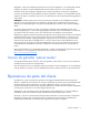
Customer self repair HP products are designed with many Customer Self Repair (CSR) parts to minimize repair time and allow for greater flexibility in performing defective parts replacement. If during the diagnosis period HP (or HP service providers or service partners) identifies that the repair can be accomplished by the use of a CSR part, HP will ship that part directly to you for replacement. There are two categories of CSR parts: • Mandatory—Parts for which customer self repair is mandatory.
Obligatoire - Pièces pour lesquelles la réparation par le client est obligatoire. Si vous demandez à HP de remplacer ces pièces, les coûts de déplacement et main d'œuvre du service vous seront facturés. Facultatif - Pièces pour lesquelles la réparation par le client est facultative. Ces pièces sont également conçues pour permettre au client d'effectuer lui-même la réparation.
NOTA: alcuni componenti HP non sono progettati per la riparazione da parte del cliente. Per rispettare la garanzia, HP richiede che queste parti siano sostituite da un centro di assistenza autorizzato. Tali parti sono identificate da un "No" nel Catalogo illustrato dei componenti. In base alla disponibilità e alla località geografica, le parti CSR vengono spedite con consegna entro il giorno lavorativo seguente.
anrufen und sich von einem Mitarbeiter per Telefon helfen lassen. Den Materialien, die mit einem CSRErsatzteil geliefert werden, können Sie entnehmen, ob das defekte Teil an HP zurückgeschickt werden muss. Wenn es erforderlich ist, das defekte Teil an HP zurückzuschicken, müssen Sie dies innerhalb eines vorgegebenen Zeitraums tun, in der Regel innerhalb von fünf (5) Geschäftstagen.
Centro de asistencia técnica de HP y recibirá ayuda telefónica por parte de un técnico. Con el envío de materiales para la sustitución de componentes CSR, HP especificará si los componentes defectuosos deberán devolverse a HP. En aquellos casos en los que sea necesario devolver algún componente a HP, deberá hacerlo en el periodo de tiempo especificado, normalmente cinco días laborables. Los componentes defectuosos deberán devolverse con toda la documentación relacionada y con el embalaje de envío.
bijbehorende documentatie worden geretourneerd in het meegeleverde verpakkingsmateriaal. Als u het defecte onderdeel niet terugzendt, kan HP u voor het vervangende onderdeel kosten in rekening brengen. Bij reparatie door de klant betaalt HP alle verzendkosten voor het vervangende en geretourneerde onderdeel en kiest HP zelf welke koerier/transportonderneming hiervoor wordt gebruikt. Neem contact op met een Service Partner voor meer informatie over het Customer Self Repair programma van HP.
Serviço de garantia apenas para peças A garantia limitada da HP pode incluir um serviço de garantia apenas para peças. Segundo os termos do serviço de garantia apenas para peças, a HP fornece as peças de reposição sem cobrar nenhuma taxa. No caso desse serviço, a substituição de peças CSR é obrigatória. Se desejar que a HP substitua essas peças, serão cobradas as despesas de transporte e mão-de-obra do serviço.
Customer self repair 13
Customer self repair 14
Customer self repair 15
Customer self repair 16
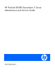
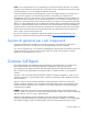
Illustrated parts catalog Mechanical components Item Description Assembly part number Spare part number Customer self repair (on page 6) 1 Access panel 394037-001 407744-001 Mandatory1 2 Front bezel 394028-003 407745-001 Mandatory1 3 Hard drive blank 376383-001 392613-001 Mandatory1 4 Media drive blank 377569-001 409006-001 Mandatory1 5 Power supply cage assembly 394020-001 408785-001 Mandatory1 6 Power supply blank 394436-001 409417-001 Mandatory1 Illustrated parts catal
Mandatory—Parts for which customer self repair is mandatory. If you request HP to replace these parts, you will be charged for the travel and labor costs of this service. 2 Optional—Parts for which customer self repair is optional. These parts are also designed for customer self repair. If, however, you require that HP replace them for you, there may or may not be additional charges, depending on the type of warranty service designated for your product.
No: Nee—Sommige HP onderdelen zijn niet ontwikkeld voor reparatie door de klant. In verband met de garantievoorwaarden moet het onderdeel door een geautoriseerde Service Partner worden vervangen. Deze onderdelen worden in de geïllustreerde onderdelencatalogus aangemerkt met "Nee". 3 Mandatory: Obrigatória—Peças cujo reparo feito pelo cliente é obrigatório. Se desejar que a HP substitua essas peças, serão cobradas as despesas de transporte e mão-de-obra do serviço.
System components Item Description Assembly part number Spare part number Customer self repair (on page 6) System components 7 Hot-plug fan, 60-mm 394035-001 407747-001 Mandatory1 8 Processor fan bracket — — — a) Processor fan bracket, 12-fan model 394023-001 408783-001 Mandatory1 b) Processor fan bracket, 6-fan model* 441011-001 442953-001 Mandatory1 Processor fan bracket plate* 419341-002 430371-001 Mandatory1 9 Illustrated parts catalog 20
Item Description Assembly part number Spare part number Customer self repair (on page 6) 10 I/O fan bracket — — — a) I/O fan bracket, 12-fan model 419315-001 408784-001 Optional2 b) I/O fan bracket, 6-fan model* 441015-001 442954-001 Optional2 Power supply — — — a) AC hot-plug power supply, 1000-W 380622-001 403781-001 Mandatory1 b) DC hot-plug power supply, 1200-W 412837-001 419613-001 Mandatory1 PCI riser cage — — — a) PCI riser cage, with non-hot-plug PCIe (standard) 41
Item Description Assembly part number Spare part number Customer self repair (on page 6) k) 1.86-GHz Intel® Xeon® processor E5205, dual-core, 1x6-MB L2 cache, 1066MHz FSB* ** 459281-001 460493-001 Optional2 l) 3.33-GHz Intel® Xeon® processor X5260, dual-core, 1x6-MB L2 cache, 1333MHz FSB* ** 455302-001 459738-001 Optional2 m) 1.6-GHz Intel® Xeon® processor E5310, quad-core, 4x2-MB L2 cache, 1066-MHz FSB* ** 433027-004 437945-001 Optional2 n) 1.
Item Description Assembly part number Spare part number Customer self repair (on page 6) aa) 3.16-GHz Intel® Xeon® processor X5460, quad-core, 2x6-MB L2 cache, 1333-MHz FSB* ** 455968-001 457879-001 Optional2 bb) 2.66-GHz Intel® Xeon® processor L5430, quad-core, 2x6-MB L2 cache, 1333MHz FSB* ** 455292-001 459735-001 Optional2 cc) 3.16-GHz Intel® Xeon® processor X5460, quad-core, 2x6-MB L2 cache, 1333-MHz FSB* ** 455968-001 457879-001 Optional2 dd) 3.
Item Description Assembly part number Spare part number Customer self repair (on page 6) 25 CD-RW/DVD-ROM drive, slimline, 24X (optional)* 383696-002 399959-001 Mandatory1 26 DVD+R/RW drive, slimline, 8X* 395911-001 399402-001 Mandatory1 Miscellaneous cable kit* — 408795-001 Mandatory1 a) Power cable, 10-pin 394038-001 — — b) Systems Insight Display cable 219049-003 — — 28 SAS cable* 361316-010 408796-001 Mandatory1 29 Data cable kit* — 408797-001 Mandatory1 a) Fan board
Item Description Assembly part number Spare part number Customer self repair (on page 6) 36 Battery, 3.
Mandatory—Parts for which customer self repair is mandatory. If you request HP to replace these parts, you will be charged for the travel and labor costs of this service. 2 Optional—Parts for which customer self repair is optional. These parts are also designed for customer self repair. If, however, you require that HP replace them for you, there may or may not be additional charges, depending on the type of warranty service designated for your product.
No: Nee—Sommige HP onderdelen zijn niet ontwikkeld voor reparatie door de klant. In verband met de garantievoorwaarden moet het onderdeel door een geautoriseerde Service Partner worden vervangen. Deze onderdelen worden in de geïllustreerde onderdelencatalogus aangemerkt met "Nee". 3 Mandatory: Obrigatória—Peças cujo reparo feito pelo cliente é obrigatório. Se desejar que a HP substitua essas peças, serão cobradas as despesas de transporte e mão-de-obra do serviço.
Removal and replacement procedures Required tools You need the following items for some procedures: • T-10/T-15 Torx screwdriver (included with the server) • HP Insight Diagnostics software ("HP Insight Diagnostics" on page 77) Safety considerations Before performing service procedures, review all the safety information. Preventing electrostatic discharge To prevent damaging the system, be aware of the precautions you need to follow when setting up the system or handling parts.
WARNING: To reduce the risk of personal injury from hot surfaces, allow the drives and the internal system components to cool before touching them. CAUTION: Do not operate the server for long periods with the access panel open or removed. Operating the server in this manner results in improper airflow and improper cooling that can lead to thermal damage.
3. After performing the installation or maintenance procedure, slide the server back into the rack: a. Press the server rail-release latches and slide the server fully into rack. WARNING: To reduce the risk of personal injury, be careful when pressing the server railrelease latches and sliding the server into the rack. The sliding rails could pinch your fingers. b. Press the server firmly into the rack to secure it in place.
1. Back up the server data. 2. Shut down the operating system as directed by the operating system documentation. NOTE: If the operating system automatically places the server in Standby mode, omit the next step. 3. Press the Power On/Standby button to place the server in Standby mode. When the server activates Standby power mode, the system power LED changes to amber. IMPORTANT: Pressing the UID button illuminates the blue UID LEDs on the front and rear panels.
NOTE: To access some components, you may need to remove the cable management arm. To access the product rear panel components, open the cable management arm: 1. Power down the server (on page 30). 2. Swing open the cable management arm. 3. Remove the cables from the cable trough. 4. Remove the cable management arm. Access panel WARNING: To reduce the risk of personal injury from hot surfaces, allow the drives and the internal system components to cool before touching them.
CAUTION: To prevent improper cooling and thermal damage, do not operate the server unless all bays are populated with either a component or a blank. Remove the component as indicated. To replace the blank, slide the blank into the bay until it locks into place. Hot-plug SAS hard drive CAUTION: To prevent improper cooling and thermal damage, do not operate the server unless all bays are populated with either a component or a blank. 1.
Power supply blank To remove the component: CAUTION: To prevent improper cooling and thermal damage, do not operate the server unless all bays are populated with either a component or a blank. 1. Access the product rear panel (on page 31). 2. Remove the power supply blank. WARNING: To reduce the risk of personal injury from hot surfaces, allow the power supply or power supply blank to cool before touching it. To replace the component, reverse the removal procedure.
3. Remove the hot-plug power supply. WARNING: To reduce the risk of electric shock or damage to the equipment, do not connect the power cord to the power supply until the power supply is installed. To replace the component: 1. Slide the hot-plug power supply into the power supply bay. 2. Connect the power cord to the power supply. 3. Install the cable management arm, if removed ("Access the product rear panel" on page 31). 4.
5. Disconnect the power cord from the power supply. 6. Remove the power supply. WARNING: To reduce the risk of electric shock, fire, and damage to the equipment, this product must be installed in accordance with the following guidelines: • This power supply is intended only for installation in HP servers located in a restricted access location. • This power supply is not intended for direct connection to the DC supply branch circuit.
WARNING: To reduce the risk of injury from electric shock hazards, do not open power supplies. Refer all maintenance, upgrades, and servicing to qualified personnel. CAUTION: Do not run the server with one AC power supply and one DC power supply installed. CAUTION: Electrostatic discharge (ESD) can damage electronic components. Be sure that you are properly grounded (earthed) before beginning any installation procedure.
2. Remove the component as indicated: To replace the component, slide the component into the bay until it is fully seated. Hot-plug fan The server supports variable fan speeds. The fans operate at minimum speed until a temperature change requires a fan speed increase to cool the server. The server shuts down in the following temperature-related scenarios: • At POST: o The BIOS suspends the server for 5 minutes if it detects a cautionary temperature level.
2. Remove the access panel ("Access panel" on page 32). 3. Remove the fan. CAUTION: Do not operate the server for long periods with the access panel open or removed. Operating the server in this manner results in improper airflow and improper cooling that can lead to thermal damage. To replace the component, reverse the removal procedure. Processor fan bracket These procedures apply to both the 6- and 12-fan configurations. If necessary, configuration-specific illustrations are provided.
4. Remove the processor fan bracket. 5. Remove all hot-plug fans from the processor fan bracket ("Hot-plug fan" on page 38). To replace the component, reverse the removal steps and press down on the top of each fan to be sure it is seated properly. Front bezel To remove the component: 1. Power down the server (on page 30). 2. Extend or remove the server from the rack ("Remove the server from the rack" on page 31). 3. Remove the access panel ("Access panel" on page 32). 4.
6. Remove the five T-15 Torx screws and detach the front bezel. To replace the component, reverse the removal procedure. Power supply cage assembly To remove the component: 1. Power down the server (on page 30). 2. Access the product rear panel (on page 31). 3. Remove all power supplies ("Hot-plug power supply" on page 34). 4. Remove the server from the rack (on page 31). 5. Remove the access panel ("Access panel" on page 32). 6. Remove the power supply cage assembly.
Systems Insight Display To remove the component: 1. Power down the server (on page 30). 2. Extend the server from the rack (on page 29). 3. Remove the access panel ("Access panel" on page 32). IMPORTANT: For this procedure, you do not need to remove the hot-plug fans from the processor fan bracket. When reinstalling the processor fan bracket, press the top of each fan to be sure it seats securely. 4. Remove the processor fan bracket ("Processor fan bracket" on page 39). 5.
6. Remove the fan board. To replace the component, reverse the removal procedure. Processor fan bracket plate To remove the component: 1. Power down the server (on page 30). 2. Extend the server from the rack (on page 29). 3. Remove the access panel ("Access panel" on page 32). IMPORTANT: For this procedure, you do not need to remove the hot-plug fans from the processor fan bracket. When reinstalling the processor fan bracket, press the top of each fan to be sure it seats securely. 4.
8. Remove the processor fan bracket plate. To replace the component, reverse the removal procedure. Media drive ejector assembly To remove the component: 1. Power down the server (on page 30). 2. Extend or remove the server from the rack ("Remove the server from the rack" on page 31). 3. Remove the access panel ("Access panel" on page 32). 4. Remove the media drive ("Media drive or blank" on page 37). 5. Remove the processor fan bracket ("Processor fan bracket" on page 39). 6.
8. Remove the ejector assembly. To replace the component, reverse the removal procedure. PPM To remove the component: 1. Power down the server (on page 30). 2. Extend the server from the rack (on page 29). 3. Remove the access panel ("Access panel" on page 32). NOTE: The appearance of compatible PPMs may vary.
4. Remove the PPM. IMPORTANT: PPM slots must be populated when processors are installed. If PPM slots are not populated, the server halts during POST or does not boot. To replace the component, reverse the removal procedure. PPM retainer To remove the component: 1. Power down the server (on page 30). 2. Extend the server from the rack (on page 29). 3. Remove the access panel ("Access panel" on page 32). 4. Remove the PPMs ("PPM" on page 45).
5. Remove the PPM retainer. To replace the component, reverse the removal procedure. Processor CAUTION: To avoid damage to the processor and system board, only authorized personnel should attempt to replace or install the processor in this server. IMPORTANT: Processor socket 1 and PPM slot 1 must be populated at all times or the server does not function properly. IMPORTANT: Always install a PPM when you install a processor. The system fails to boot if the corresponding PPM is missing.
4. Open the heatsink retaining bracket. 5. Remove the heatsink.
6. Open the processor retaining latch and the processor socket retaining bracket. 7. Using your fingers, remove the failed processor. To replace a processor: IMPORTANT: Be sure the processor remains inside the processor installation tool.
1. If the processor has separated from the installation tool, carefully re-insert the processor in the tool. 2. Align the processor installation tool with the socket and install the spare processor. CAUTION: The processor is designed to fit one way into the socket. Use the alignment guides on the processor and socket to properly align the processor with the socket. Refer to the server hood label for specific instructions.
3. Press down firmly until the processor installation tool clicks and separates from the processor, and then remove the processor installation tool. 4. Close the processor retaining latch and the processor socket retaining bracket. 5. Clean the old thermal grease from the heatsink with the alcohol swab. Allow the alcohol to evaporate before continuing.
6. Apply all the grease to the top of the processor in one of the following patterns to ensure even distribution. 7. Install the heatsink.
8. Close and lock the heatsink retaining latches. 9. Install the access panel ("Access panel" on page 32). 10. Install the server into the rack. 11. Power up the server.
5. Remove the cache module. To replace the component, reverse the removal procedure. CAUTION: To prevent damage to the cache module during installation, be sure the cache module is fully inserted before pressing down. Removing the battery pack To remove the component: 1. Power down the server (on page 30). 2. Extend or remove the server from the rack ("Remove the server from the rack" on page 31). 3. Remove the access panel ("Access panel" on page 32). 4.
Recovering data from the battery-backed write cache If the server fails, use the following procedure to recover data temporarily stored in the BBWC. CAUTION: Before starting this procedure, read the information about protecting against electrostatic discharge ("Preventing electrostatic discharge" on page 28). 1. 2. Perform one of the following: o Set up a recovery server station using an identical server model. Do not install any internal drives or BBWC in this server. (HP recommends this option.
5. Remove all hard drive cables from the air baffle. 6. Remove the air baffle. To replace the component, reverse the removal procedure. FBDIMMs To remove the component: 1. Power down the server (on page 30). 2. Extend or remove the server from the rack ("Remove the server from the rack" on page 31). 3. Remove the access panel ("Access panel" on page 32). 4. Remove the battery pack ("Removing the battery pack" on page 54). 5. Remove the air baffle ("Air baffle" on page 55). 6.
To replace the component, reverse the removal procedure. Memory options This server contains eight FBDIMM slots. You can expand server memory by installing supported Registered DDR-2 FBDIMMs. Memory configurations The server supports the following Advanced Memory Protection (AMP) options to optimize server availability. • Advanced ECC—supports up to 64 GB of active memory using 8-GB FBDIMMs.
memory errors. Advanced ECC provides additional protection over Standard ECC because it is possible to correct certain memory errors that would otherwise be uncorrectable and result in a server failure. Whereas standard ECC can correct single-bit memory errors, Advanced ECC can correct single-bit memory errors and multi-bit memory errors if all failed bits are on the same DRAM device on the FBDIMM.
Online spare FBDIMM configuration requirements (in addition to general configuration requirements): • When only bank A is being used, it must be fully populated with dual-rank FBDIMMs. • If banks A and C are being used, they must be fully populated. • If installed, bank A and bank C must contain FBDIMMs with identical part numbers. • If installed, bank B and bank D must also contain FBDIMMs with identical part numbers.
Power supply backplane To remove the component: 1. Power down the server (on page 30). 2. Remove all power supplies ("Hot-plug power supply" on page 34). 3. Extend or remove the server from the rack ("Remove the server from the rack" on page 31). 4. Remove the access panel ("Access panel" on page 32). 5. Remove the power supply backplane. To replace the component, reverse the removal procedure. Hard drive backplane To remove the component: 1. Power down the server (on page 30). 2.
5. Remove the hard drive backplane. To replace the component, reverse the removal procedure. Hard drive backplane retainer To remove the component: 1. Power down the server (on page 30). 2. Extend or remove the server from the rack ("Remove the server from the rack" on page 31). 3. Remove the access panel ("Access panel" on page 32). 4. Remove all hot-plug hard drives ("Hot-plug SAS hard drive" on page 33). 5. Remove the hard drive backplane ("Hard drive backplane" on page 60). 6.
PCI riser cage To remove the component: CAUTION: To prevent damage to the server or expansion boards, power down the server and remove all AC power cords before removing or installing the PCI riser cage. 1. Power down the server (on page 30). 2. Extend the server from the rack (on page 29). 3. Remove the access panel ("Access panel" on page 32). 4. Disconnect any internal or external cables connected to any existing expansion boards. 5. Press the blue button to release the black knob. 6.
4. Remove the expansion slot cover. To replace the component, reverse the removal procedure. Expansion slot covers (3, 4, and 5) CAUTION: To prevent damage to the server or expansion boards, power down the server and remove all AC power cords before removing or installing the PCI riser cage. CAUTION: To prevent improper cooling and thermal damage, do not operate the server unless all PCI slots have either an expansion slot cover or an expansion board installed. 1. Power down the server (on page 30). 2.
To replace the component, reverse the removal procedure. Expansion slot cover retainer (slots 1 and 2) To remove the component: 1. Power down the server (on page 30). 2. Extend or remove the server from the rack ("Remove the server from the rack" on page 31). 3. Remove the access panel ("Access panel" on page 32). 4. Remove the expansion slot cover retainer. To replace the component, reverse the removal procedure. Expansion boards Expansion board (slots 1 and 2) To remove the component: 1.
5. Remove the expansion board. CAUTION: To prevent improper cooling and thermal damage, do not operate the server unless all PCI slots have either an expansion slot cover or an expansion board installed. To replace the component, reverse the removal procedure. Removing expansion board (slots 3, 4, and 5) To remove the component: 1. Power down the server (on page 30). 2. Extend or remove the server from the rack ("Remove the server from the rack" on page 31). 3.
6. Remove the expansion board. CAUTION: To prevent improper cooling and thermal damage, do not operate the server unless all PCI slots have either an expansion slot cover or an expansion board installed. To replace the component, reverse the removal procedure. Battery If the server no longer automatically displays the correct date and time, you may need to replace the battery that provides power to the real-time clock.
5. Remove the battery. IMPORTANT: Replacing the system board battery resets the system ROM to its default configuration. After replacing the battery, reconfigure the system through RBSU. To replace the component, reverse the removal procedure. For more information about battery replacement or proper disposal, contact an authorized reseller or an authorized service provider. System board To remove the component: 1. Power down the server (on page 30). 2.
12. Remove all FBDIMMs ("FBDIMMs" on page 56). 13. Remove the processors. 14. Remove the PPMs ("PPM" on page 45). 15. Disconnect all cables connected to the system board. 16. Identify the eight alignment keys and keyhole locations. 17. Loosen the system board thumbscrew. 18. Remove the system board. 19. Remove the I/O fan bracket ("I/O fan bracket" on page 69). IMPORTANT: If replacing the system board or clearing NVRAM, you must re-enter the server serial number through RBSU.
1. During the server startup sequence, press the F9 key to access RBSU. 2. Select the System Options menu. 3. Select Serial Number. The following warning is displayed: WARNING! WARNING! WARNING! The serial number is loaded into the system during the manufacturing process and should NOT be modified. This option should only be used by qualified service personnel. This value should always match the serial number sticker located on the chassis. 4. Press the Enter key to clear the warning. 5.
For ease of removal, invert the system board. To replace the component: 1.
o 12-fan configuration 2. Secure the I/O fan bracket to the system board. 3. Install the system board. 4. Install the PPMs. 5. Install the FBDIMMs. 6. Install the air baffle. 7. Install the battery pack. 8. Install all hot-plug fans in the I/O fan bracket. 9. Install the processor fan bracket. 10. Install the PCI riser cage. 11. Install the power supply cage assembly. 12. Install the access panel ("Access panel" on page 32). 13. Install the server.
14. Install the power supplies. 15. Power up the server.
Cabling SAS hard drive cabling PCI SAS cabling to an HP Smart Array P400i Controller PCI SAS cabling to optional expansion board controller Cabling 73
Fan board cabling Hard drive backplane power cabling Cabling 74
Media drive bay cabling Battery cabling for BBWC NOTE: Use the retaining clip to manage excess cable slack.
Systems Insight Display cabling Cabling 76
Diagnostic tools Troubleshooting resources The HP ProLiant Servers Troubleshooting Guide provides procedures for resolving common problems and comprehensive courses of action for fault isolation and identification, error message interpretation, issue resolution, and software maintenance on ProLiant servers and server blades. This guide includes problemspecific flowcharts to help you navigate complex troubleshooting processes. To view the guide, select a language: • English (http://www.hp.
HP Insight Diagnostics Online Edition is a web-based application that captures system configuration and other related data needed for effective server management. Available in Microsoft® Windows® and Linux versions, the utility helps to ensure proper system operation. For more information or to download the utility, refer to the HP website (http://www.hp.com/servers/diags).
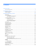
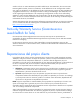
Component identification Front panel components Item Description 1 Media drive bay (IDE/diskette multibay) 2 Video connector 3 USB connectors (2) 4 Systems Insight Display 5 Hard drive bays 6 Quick release levers (2) Component identification 79
Front panel LEDs and buttons Item Description Status 1 UID LED button Blue = Activated Flashing = System being remotely managed Off = Deactivated 2 Internal health LED Green = Normal Amber = System degraded. To identify component in degraded state, refer to Systems Insight Display LEDs. Red = System critical. To identify component in critical state, refer to Systems Insight Display LEDs. 3 External health LED (power supply) Green = Normal Amber = Power redundancy failure.
Systems Insight Display LEDs Item Description Status 1 Online spare Off = No protection Green = Protection enabled Amber = Memory failure occurred Flashing amber = Memory configuration error 2 Mirror Off = No protection Green = Protection enabled Amber = Memory failure occurred Flashing amber = Memory configuration error All other LEDs Off = Normal Amber = Failure IMPORTANT: If more than one FBDIMM slot LED is illuminated, further troubleshooting is required.
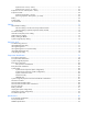
Rear panel components Item Description Color 1 Expansion slot 1 — 2 Expansion slot 2 — 3 Expansion slot 3 — 4 Expansion slot 4 — 5 Expansion slot 5 — 6 T-10/T-15 Torx screwdriver — 7 External option blank — 8 NIC 2 connector — 9 NIC 1 connector — 10 Power supply bay 2 — 11 Power cord connector Black 12 Power supply bay 1 (populated) — 13 iLO 2 connector — 14 Video connector Blue 15 USB connectors (2) Black 16 Serial connector — 17 Mouse connector Green
Item PCIe Mixed PCIe/PCI-X 3 x4, slot 3, bus C x8, slot 3, bus C 4 x8, slot 4, bus D 64-bit/133-MHz, slot 4, bus D 5 x8, slot 5, bus E 64-bit/133-MHz, slot 5, bus D x4 slots: x8 cards are supported, but will run at x4 speeds. x8 slots: x16 cards are supported, but will run at x8 speeds. All slots are non-hot-plug.
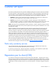
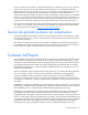
System board System board components (6-fan configuration) Item Description 1 Fan board connector 2 PPM 1 3 PPM 2 4 Power supply backplane connector 5 PCIe slot 1 6 PCIe slot 2 7 NMI jumper 8 iLO 2 diagnostic LEDs 9 System maintenance switch 10 Internal USB connector* 11 System battery 12 PCI riser cage connector 13 Fan 2 connector 14 Fan 1 connector 15 FBDIMM slots (1-8) 16 Multibay interface connector 17 Processor socket 1 18 Processor socket 2 * The lower USB connec
System board components (12-fan configuration) Item Description 1 Fan board connector 2 PPM 1 3 PPM 2 4 Power supply backplane connector 5 PCIe slot 1 6 PCIe slot 2 7 NMI jumper 8 iLO 2 diagnostic LEDs 9 System maintenance switch 10 Internal USB connector* 11 System battery 12 PCI riser cage connector 13 Fan 4 connector 14 Fan 2 connector 15 Fan 3 connector 16 Fan 1 connector 17 FBDIMM slots (1-8) 18 Multibay interface connector 19 Processor socket 1 20 Processor so
System maintenance switch Position Default Function S1 Off Off = iLO 2 security is enabled. On = iLO 2 security is disabled. S2 Off Off = System configuration can be modified. On = System configuration is locked and cannot be modified. S3 Off Reserved S4 Off Reserved S5 Off Off = Power-on password is enabled. On = Power-on password is disabled. S6 Off Off = Normal On = ROM treats system configuration as invalid.
FBDIMM slots FBDIMM slots are numbered sequentially (1 through 8) and the paired banks are identified by the letters A, B, C, and D. Systems Insight Display LEDs and internal health LED combinations When the internal health LED on the front panel illuminates either amber or red, the server is experiencing a health event. Combinations of illuminated system LEDs and the internal health LED indicate system status.
Systems Insight Display LED and color Internal health LED color Status FBDIMM failure, all slots in all banks (amber) Red One or more FBDIMMs has failed. Test each bank of FBDIMMs by removing all other FBDIMMs. Isolate the failed FBDIMM by replacing each FBDIMM in a bank with a known working FBDIMM. Online spare memory (amber) Amber Bank X failed over to the online spare memory bank. Online spare memory (flashing amber) Red Invalid online spare memory configuration.
SAS and SATA hard drive LEDs Item Description 1 Fault/UID LED (amber/blue) 2 Online LED (green) SAS and SATA hard drive LED combinations Online/activity LED (green) Fault/UID LED (amber/blue) Interpretation On, off, or flashing Alternating amber and blue The drive has failed, or a predictive failure alert has been received for this drive; it also has been selected by a management application.
Online/activity LED (green) Fault/UID LED (amber/blue) Interpretation Flashing irregularly Off The drive is active, and it is operating normally. Off Steadily amber A critical fault condition has been identified for this drive, and the controller has placed it offline. Replace the drive as soon as possible. Off Amber, flashing regularly (1 Hz) A predictive failure alert has been received for this drive. Replace the drive as soon as possible.
Battery pack LEDs Item ID Color Description 1 Green System Power LED. This LED glows steadily when the system is powered up and 12 V system power is available. This power supply is used to maintain the battery charge and provide supplementary power to the cache microcontroller. 2 Green Auxiliary Power LED. This LED glows steadily when 3.3V auxiliary voltage is detected.
LED3 pattern LED4 pattern Interpretation — One blink per second The battery pack is below the minimum charge level and is being charged. Features that require a battery (such as write cache, capacity expansion, stripe size migration, and RAID migration) are temporarily unavailable until charging is complete. The recharge process takes between 15 minutes and two hours, depending on the initial capacity of the battery.
Hot-plug fans (12-fan configuration) For server models that support 12 fans, the fan configuration operates in redundant mode when all 12 fans are installed.
*Only the 12-fan configuration supports all connectors.
Specifications Environmental specifications Specification Value Temperature range* Operating 10°C to 35°C (50°F to 95°F) Shipping -30°C to 50°C (-22°F to 122°F) Storage -30°C to 60°C (-22°F to 140°F) Maximum wet bulb temperature 28°C (82.4°F) Relative humidity (noncondensing)** Operating 10% to 90% Non-operating 5% to 95% * All temperature ratings shown are for sea level. An altitude derating of 1°C per 300 m (1.8°F per 1,000 ft) to 3048 m (10,000 ft) is applicable. No direct sunlight allowed.
BTUs per hour 3344 at 100V to 120V AC input 3277 at 200V to 240V AC input Power supply output Rated steady-state power 800 W at 100V AC input 850 W at 120V AC input 1000 W at 200V to 240V AC input Maximum peak power 800 W at 100V AC input 850 W at 120V AC input 1000 W at 200V to 240V AC input FBDIMM specifications Specification Value Type FBDIMM, PC2-5300F, Fully-Buffered DIMMs Size 512-MB, 1-GB, 2-GB, 4-GB, 8-GB Width 72 bits Upgrade requirement * FBDIMMs must be installed in pairs within a
Specification Value Drive height One-third height Drive rotation 300 rpm Transfer rate High 500 Kb/s Low 250 Kb/s Bytes/sector 512 Sectors per track (high/low) 18/9 Tracks per side (high/low) 80/80 Access times Track-to-track (high/low) 3 ms/6 ms Average (high/low) 169 ms/94 ms Setting time 15 ms Latency average 100 ms Cylinders (high/low) 80/80 Read/write heads 2 CD-ROM drive specifications Specification Value Disk formats CD-ROM (modes 1 and 2); mixed mode (audio and data co
Specification Value Track pitch 1.6 µm (6.3 × 10⁻⁷ in) Cache/buffer 128 KB Startup time < 10 s Stop time < 5 s (single); < 30 s (multisession) Laser parameters Type Semiconductor laser GaAs Wave length 700 ± 25 nm Divergence angle 53.5° ± 1.5° Output power 0.
Specification Value Track pitch 0.74 µm (3.15 × 10⁻⁷ in) DVD-ROM 1.6 µm (6.3 × 10⁻⁷ in) CD-ROM Cache/buffer 128 KB Startup time < 15 s Stop time < 5 s (single); < 30 s (multisession) Laser parameters Type Semiconductor laser GaAs Wave length 700 ± 25 nm Divergence angle 53.5° ± 1.5° Output power 0.
Acronyms and abbreviations ABEND abnormal end ASR Automatic Server Recovery BBWC battery-backed write cache DDR double data rate FBDIMM fully buffered DIMM IDE integrated device electronics iLO Integrated Lights-Out IML Integrated Management Log NMI non-maskable interrupt NVRAM non-volatile memory ORCA Option ROM Configuration for Arrays PCIe peripheral component interconnect express Acronyms and abbreviations 100
PCI-X peripheral component interconnect extended POST Power-On Self Test PPM processor power module RBSU ROM-Based Setup Utility RDP Rapid Deployment Pack SAS serial attached SCSI SATA serial ATA SDRAM synchronous dynamic RAM UID unit identification USB universal serial bus VHDCI very high density cable interconnect Acronyms and abbreviations 101
Index A access panel 32 adapter LEDs 80, 83 ADU (Array Diagnostic Utility) 78 air baffle 55 Array Diagnostic Utility (ADU) 78 B battery 66, 86 battery cabling for BBWC 75 battery pack LEDs 91 battery-backed write cache (BBWC) 53, 55, 91 battery-backed write cache battery pack 53, 54, 75 bezel, front 40 blue screen event 86 buttons 79, 80, 83 C cable management arm 31 cables 73 cabling 73, 74, 75, 76 cabling, BBWC 75 cabling, fan board 74 cabling, hard drive backplane 74 cabling, hot-plug SAS hard drive 73
I P I/O fan bracket 69 illustrated parts catalog 17 iLO 2 connector 82 IML (Integrated Management Log) 78 Insight Diagnostics 77, 78 Integrated Management Log (IML) 78 internal health LED 80, 87 part numbers 17, 20 PCI riser cage 62 PCI slots 64, 65, 82, 83 power cord connector 82 power LEDs, system 80, 82, 91 Power On/Standby button 80 power requirements 96 power supply 34, 35, 82, 96 power supply backplane 60 power supply blank 34 power supply cage assembly 41 power supply LEDs 83 powering down 30 PPM
system board components 84, 85 system components 20, 79 system maintenance switch 86 system power LED 80, 91 Systems Insight Display 76, 79 Systems Insight Display cabling 76 T telco racks 31 tools 28, 77 Torx screwdriver 82 troubleshooting 77 U UID LED 80, 83, 86 USB connectors 79, 82 utilities 77 utilities, deployment 77 V video connector 79, 82 W warnings 28 Index 104