HP ProLiant DL380 Generation 5 Server User Guide Part Number 403166-005 September 2007 (Fifth Edition)
© Copyright 2006, 2007 Hewlett-Packard Development Company, L.P. The information contained herein is subject to change without notice. The only warranties for HP products and services are set forth in the express warranty statements accompanying such products and services. Nothing herein should be construed as constituting an additional warranty. HP shall not be liable for technical or editorial errors or omissions contained herein. Microsoft and Windows are U.S.
Contents Component identification ............................................................................................................... 7 Front panel components ............................................................................................................................. 7 Front panel LEDs and buttons ...................................................................................................................... 8 Systems Insight Display LEDs .................................
Installing the server into the rack................................................................................................................ 33 Installing the operating system................................................................................................................... 35 Powering up and configuring the server ..................................................................................................... 35 Registering the server.............................................
Internal USB functionality ................................................................................................................ 69 Diagnostic tools ...................................................................................................................................... 69 HP Insight Diagnostics .................................................................................................................... 69 HP Insight Diagnostics survey functionality ...........................
Taiwan battery recycling notice................................................................................................................. 95 Power cord statement for Japan................................................................................................................. 95 Electrostatic discharge ................................................................................................................. 96 Preventing electrostatic discharge ........................................
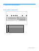
Component identification Front panel components Item Description 1 Media drive bay (IDE/diskette multibay) 2 Video connector 3 USB connectors (2) 4 Systems Insight Display 5 Hard drive bays 6 Quick release levers (2) Component identification 7
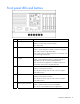
Front panel LEDs and buttons Item Description Status 1 UID LED button Blue = Activated Flashing = System being remotely managed Off = Deactivated 2 Internal health LED Green = Normal Amber = System degraded. To identify component in degraded state, refer to Systems Insight Display LEDs. Red = System critical. To identify component in critical state, refer to Systems Insight Display LEDs. 3 External health LED (power supply) Green = Normal Amber = Power redundancy failure.
Systems Insight Display LEDs Item Description Status 1 Online spare Off = No protection Green = Protection enabled Amber = Memory failure occurred Flashing amber = Memory configuration error 2 Mirror Off = No protection Green = Protection enabled Amber = Memory failure occurred Flashing amber = Memory configuration error All other LEDs Off = Normal Amber = Failure IMPORTANT: If more than one FBDIMM slot LED is illuminated, further troubleshooting is required.
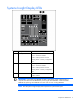
Rear panel components Item Description Color 1 Expansion slot 1 — 2 Expansion slot 2 — 3 Expansion slot 3 — 4 Expansion slot 4 — 5 Expansion slot 5 — 6 T-10/T-15 Torx screwdriver — 7 External option blank — 8 NIC 2 connector — 9 NIC 1 connector — 10 Power supply bay 2 — 11 Power cord connector Black 12 Power supply bay 1 (populated) — 13 iLO 2 connector — 14 Video connector Blue 15 USB connectors (2) Black 16 Serial connector — 17 Mouse connector Green
Item PCIe Mixed PCIe/PCI-X 3 x4, slot 3, bus C x8, slot 3, bus C 4 x8, slot 4, bus D 64-bit/133-MHz, slot 4, bus D 5 x8, slot 5, bus E 64-bit/133-MHz, slot 5, bus D x4 slots: x8 cards are supported, but will run at x4 speeds. x8 slots: x16 cards are supported, but will run at x8 speeds. All slots are non-hot-plug.
System board System board components (6-fan configuration) Item Description 1 Fan board connector 2 PPM 1 3 PPM 2 4 Power supply backplane connector 5 PCIe slot 1 6 PCIe slot 2 7 NMI jumper 8 iLO 2 diagnostic LEDs 9 System maintenance switch 10 Internal USB connector* 11 System battery 12 PCI riser cage connector 13 Fan 2 connector 14 Fan 1 connector 15 FBDIMM slots (1-8) 16 Multibay interface connector 17 Processor socket 1 18 Processor socket 2 * The lower USB connec
System board components (12-fan configuration) Item Description 1 Fan board connector 2 PPM 1 3 PPM 2 4 Power supply backplane connector 5 PCIe slot 1 6 PCIe slot 2 7 NMI jumper 8 iLO 2 diagnostic LEDs 9 System maintenance switch 10 Internal USB connector* 11 System battery 12 PCI riser cage connector 13 Fan 4 connector 14 Fan 2 connector 15 Fan 3 connector 16 Fan 1 connector 17 FBDIMM slots (1-8) 18 Multibay interface connector 19 Processor socket 1 20 Processor so
System maintenance switch Position Default Function S1 Off Off = iLO 2 security is enabled. On = iLO 2 security is disabled. S2 Off Off = System configuration can be modified. On = System configuration is locked and cannot be modified. S3 Off Reserved S4 Off Reserved S5 Off Off = Power-on password is enabled. On = Power-on password is disabled. S6 Off Off = Normal On = ROM treats system configuration as invalid.
FBDIMM slots FBDIMM slots are numbered sequentially (1 through 8) and the paired banks are identified by the letters A, B, C, and D. Systems Insight Display LEDs and internal health LED combinations When the internal health LED on the front panel illuminates either amber or red, the server is experiencing a health event. Combinations of illuminated system LEDs and the internal health LED indicate system status.
Systems Insight Display LED and color Internal health LED color Status FBDIMM failure, all slots in one bank (amber) Red One or more FBDIMMs has failed. Test each bank of FBDIMMs by removing all other FBDIMMs. Isolate the failed FBDIMM by replacing each FBDIMM in a bank with a known working FBDIMM. FBDIMM failure, all slots in all banks (amber) Red One or more FBDIMMs has failed. Test each bank of FBDIMMs by removing all other FBDIMMs.
SAS and SATA hard drive LEDs Item Description 1 Fault/UID LED (amber/blue) 2 Online LED (green) SAS and SATA hard drive LED combinations Online/activity LED (green) Fault/UID LED (amber/blue) On, off, or flashing Alternating amber and The drive has failed, or a predictive failure alert has been blue received for this drive; it also has been selected by a management application.
Online/activity LED (green) Fault/UID LED (amber/blue) Interpretation Flashing irregularly Amber, flashing regularly (1 Hz) The drive is active, but a predictive failure alert has been received for this drive. Replace the drive as soon as possible. Flashing irregularly Off The drive is active, and it is operating normally. Off Steadily amber A critical fault condition has been identified for this drive, and the controller has placed it offline. Replace the drive as soon as possible.
Battery pack LEDs Item ID Color Description 1 Green System Power LED. This LED glows steadily when the system is powered up and 12 V system power is available. This power supply is used to maintain the battery charge and provide supplementary power to the cache microcontroller. 2 Green Auxiliary Power LED. This LED glows steadily when 3.3V auxiliary voltage is detected.
LED3 pattern LED4 pattern Interpretation — One blink per second The battery pack is below the minimum charge level and is being charged. Features that require a battery (such as write cache, capacity expansion, stripe size migration, and RAID migration) are temporarily unavailable until charging is complete. The recharge process takes between 15 minutes and two hours, depending on the initial capacity of the battery.
Hot-plug fans (12-fan configuration) For server models that support 12 fans, the fan configuration operates in redundant mode when all 12 fans are installed. For more information, see "Hot-plug fan operation (on page 28).
Item Description 7 Fan board system connector *Only the 12-fan configuration supports all connectors.
Operations Power up the server To power up the server, press the Power On/Standby button. Power down the server WARNING: To reduce the risk of personal injury, electric shock, or damage to the equipment, remove the power cord to remove power from the server. The front panel Power On/Standby button does not completely shut off system power. Portions of the power supply and some internal circuitry remain active until AC power is removed.
3. After performing the installation or maintenance procedure, slide the server back into the rack: a. Press the server rail-release latches and slide the server fully into rack. WARNING: To reduce the risk of personal injury, be careful when pressing the server railrelease latches and sliding the server into the rack. The sliding rails could pinch your fingers. b. Press the server firmly into the rack to secure it in place.
To remove the component: 1. Power down the server if performing a non-hot-plug installation or maintenance procedure ("Power down the server" on page 23). 2. Extend the server from the rack (on page 23). 3. Use the T-15 Torx screwdriver attached to the rear of the server to loosen the security screw on the hood latch. 4. Lift up on the hood latch handle and remove the access panel. Install the access panel 1. Place the access panel on top of the server with the hood latch open.
Install the PCI riser cage CAUTION: To prevent damage to the server or expansion boards, power down the server and remove all AC power cords before removing or installing the PCI riser cage. 1. Align the PCI riser cage with the chassis and slide it into place. 2. Tighten the thumbscrews to secure the PCI riser cage: a. Press down the black knob while turning clockwise, until fully tightened. b.
6. Connect any required external cables to the expansion board. Refer to the documentation that ships with the expansion board. 7. Power up the server (on page 23). Access the product rear panel Cable management arm with left-hand swing To access the server rear panel, open the cable management arm. Cable management arm with right-hand swing NOTE: To access some components, you may need to remove the cable management arm. To access the product rear panel components, open the cable management arm: 1.
4. Remove the cable management arm. Hot-plug fan operation The server supports variable fan speeds. The fans operate at minimum speed until a temperature change requires a fan speed increase to cool the server. The server shuts down in the following temperature-related scenarios: • At POST: o The BIOS suspends the server for 5 minutes if it detects a cautionary temperature level.
Setup Optional installation services Delivered by experienced, certified engineers, HP Care Pack services help you keep your servers up and running with support packages tailored specifically for HP ProLiant systems. HP Care Packs let you integrate both hardware and software support into a single package. A number of service level options are available to meet your needs.
Optimum environment When installing the server in a rack, select a location that meets the environmental standards described in this section. Space and airflow requirements To allow for servicing and adequate airflow, observe the following space and airflow requirements when deciding where to install a rack: • Leave a minimum clearance of 63.5 cm (25 in) in front of the rack. • Leave a minimum clearance of 76.2 cm (30 in) behind the rack. • Leave a minimum clearance of 121.
Temperature requirements To ensure continued safe and reliable equipment operation, install or position the system in a wellventilated, climate-controlled environment. The maximum recommended ambient operating temperature (TMRA) for most server products is 35°C (95°F). The temperature in the room where the rack is located must not exceed 35°C (95°F).
Because of the high ground-leakage currents associated with multiple servers connected to the same power source, HP recommends the use of a PDU that is either permanently wired to the building’s branch circuit or includes a nondetachable cord that is wired to an industrial-style plug. NEMA locking-style plugs or those complying with IEC 60309 are considered suitable for this purpose. Using common power outlet strips for the server is not recommended.
Installing hardware options Install any hardware options before initializing the server. For options installation information, refer to the option documentation. For server-specific information, refer to "Hardware options installation (on page 37)." Installing the server into the rack CAUTION: Always plan the rack installation so that the heaviest item is on the bottom of the rack. Install the heaviest item first, and continue to populate the rack from the bottom to the top. 1.
14 Video connector Blue 15 USB connectors (2) Black 16 Serial connector — 17 Mouse connector Green 18 Keyboard connector Purple WARNING: To reduce the risk of electric shock, fire, or damage to the equipment, do not plug telephone or telecommunications connectors into RJ-45 connectors. 3. Connect the power cord to the rear of the server. 4. Install the power cord anchor on the handle of the power supply. NOTE: Peripheral device cables are removed for clarity. 5.
6. Connect the power cord to the AC power source. WARNING: To reduce the risk of electric shock or damage to the equipment: • Do not disable the power cord grounding plug. The grounding plug is an important safety feature. • Plug the power cord into a grounded (earthed) electrical outlet that is easily accessible at all times. • Unplug the power cord from the power supply to disconnect power to the equipment. • Do not route the power cord where it can be walked on or pinched by items placed against it.
While the server boots, RBSU and the ORCA utility are automatically configured to prepare the server for operating system installation. To configure these utilities manually: • Press the F8 key when prompted during the array controller initialization to configure the array controller using ORCA. • Press the F9 key when prompted during the boot process to change the server settings using RBSU. The system is set up by default for the English language.
Hardware options installation Introduction If more than one option is being installed, read the installation instructions for all the hardware options and identify similar steps to streamline the installation process. WARNING: To reduce the risk of personal injury from hot surfaces, allow the drives and the internal system components to cool before touching them. CAUTION: To prevent damage to electrical components, properly ground the server before beginning any installation procedure.
3. Remove the access panel (on page 24). 4. Open the heatsink retaining bracket. CAUTION: The pins on the processor socket are very fragile. Any damage to them may require replacing the system board. CAUTION: Failure to completely open the processor locking lever prevents the processor from seating during installation, leading to hardware damage. 5. Open the processor retaining latch and the processor socket retaining bracket.
6. Remove the processor socket protective cover. IMPORTANT: Be sure the processor remains inside the processor installation tool. 7. If the processor has separated from the installation tool, carefully re-insert the processor in the tool.
8. Align the processor installation tool with the socket and install the processor. 9. Press down firmly until the processor installation tool clicks and separates from the processor, and then remove the processor installation tool.
10. Close the processor socket retaining bracket and the processor retaining latch. CAUTION: To prevent possible server malfunction or damage to the equipment, be sure to completely close the processor locking lever. 11. Remove the heatsink cover. CAUTION: After the cover is removed, do not touch the thermal interface media.
12. Install the heatsink. 13. Close the heatsink retaining bracket. 14. Open the latches on the corresponding PPM slot.
15. Install the PPM. 16. Close the latches. NOTE: The appearance of compatible PPMs may vary. NOTE: The PPM is keyed and the key must be aligned when installed. 17. Install the access panel (on page 25).
Memory options This server contains eight FBDIMM slots. You can expand server memory by installing supported Registered DDR-2 FBDIMMs. Memory configurations The server supports the following Advanced Memory Protection (AMP) options to optimize server availability. • Advanced ECC supporting up to 16 GB of active memory using 2-GB FBDIMMs.
correctable errors exceeds a pre-defined threshold rate. The server does not fail because of correctable memory errors. Advanced ECC provides additional protection over Standard ECC because it is possible to correct certain memory errors that would otherwise be uncorrectable and result in a server failure. Whereas standard ECC can correct single-bit memory errors, Advanced ECC can correct single-bit memory errors and multi-bit memory errors if all failed bits are on the same DRAM device on the FBDIMM.
• Branch 1 contains banks B and D Online spare FBDIMM configuration requirements (in addition to general configuration requirements): • When only bank A is being used, it must be fully populated with dual-rank FBDIMMs. • If banks A and C are being used, they must be fully populated. • If installed, bank A and bank C must contain FBDIMMs with identical part numbers. • If installed, bank B and bank D must also contain FBDIMMs with identical part numbers.
Installing FBDIMMs CAUTION: To avoid damage to the hard drives, memory, and other system components, the air baffle, drive blanks, and access panel must be installed when the server is powered up. 1. Power down the server (on page 23). 2. Extend the server from the rack (on page 23). 3. Remove the access panel (on page 24). 4. Move the hard drive cables. 5. Remove the air baffle. 6. Open the FBDIMM slot latches. 7. Install the FBDIMM. 8. Install the air baffle. 9.
Installing a hot-plug SAS hard drive 1. Remove the SAS hard drive blank. 2. Install the hard drive. 3. Determine the status of the hard drive from the hot-plug SAS hard drive LED combinations ("SAS and SATA hard drive LED combinations" on page 17). Removing a hot-plug SAS hard drive CAUTION: To prevent improper cooling and thermal damage, do not operate the server unless all bays are populated with either a component or a blank. 1.
3. Remove the hard drive. Media drive option 1. Power down the server (on page 23). 2. Remove the existing media drive option or blank.
3. Slide the CD/DVD-ROM drive or diskette drive into the drive bay. Redundant hot-plug AC power supply option CAUTION: To prevent improper cooling and thermal damage, do not operate the server unless all bays are populated with either a component or a blank. 1. Access the product rear panel (on page 27). 2. Remove the power supply blank. WARNING: To reduce the risk of personal injury from hot surfaces, allow the power supply or power supply blank to cool before touching it.
3. Slide the power supply into the power supply bay. 4. Connect the power cord to the power supply. 5. Route the power cord through the power cord anchor or cable management arm. 6. Reposition the cable management arm into the operating position. 7. Connect the power cord to the power source. 8. Be sure that the power supply LED is green ("Rear panel LEDs and buttons" on page 11). 9. Be sure that the front panel external health LED is green ("Front panel LEDs and buttons" on page 8).
WARNING: To reduce the risk of personal injury or damage to the equipment, the installation of power supplies should be performed only by individuals who are qualified in servicing server equipment and trained to deal with products capable of producing hazardous energy levels. WARNING: To reduce the risk of personal injury from hot surfaces, observe the thermal labels on each power supply or module. WARNING: To reduce the risk of injury from electric shock hazards, do not open power supplies.
2. Slide the power supply into the power supply bay until the release/lock lever clicks, securing the power supply. 3. Connect the power cord to the power supply. 4. Tighten the two retaining screws on either side of the power cord connector. 5. Route the power cord: o If the cable management arm has a left-hand swing, route the power cord through the cable management arm. o If the cable management arm has a right-hand swing, remove the cable management arm or convert it for left-hand swing.
4. Remove the expansion slot cover. 5. Install the expansion board. 6. Connect any required internal or external cables to the expansion board. Refer to the documentation that ships with the expansion board. 7. Install the access panel (on page 25). Removing expansion slot covers (slots 3, 4, and 5) CAUTION: To prevent damage to the server or expansion boards, power down the server and remove all AC power cords before removing or installing the PCI riser cage.
5. Remove the expansion slot cover. Installing an expansion board (slot 3, 4, or 5) CAUTION: To prevent damage to the server or expansion boards, power down the server and remove all AC power cords before removing or installing the PCI riser cage. 1. Power down the server (on page 23). 2. Extend the server from the rack (on page 23). 3. Remove the access panel (on page 24). 4. Remove the PCI riser cage (on page 25). 5. Remove the expansion slot cover. 6. Unlock the PCI retaining clip.
7. Install the expansion board: 8. Lock the PCI retaining clip. 9. Install the PCI riser cage (on page 26). 10. Connect any required internal or external cables to the expansion board. Refer to the documentation that ships with the expansion board. 11. Install the access panel (on page 25).
6. Remove the PCI riser board. 7. Install the optional riser board. 8. Install any expansion boards. ("Expansion board options" on page 53) 9. Install the PCI riser cage (on page 26). 10. Install the access panel (on page 25). 11. Install the server into the rack. 12. Power up the server (on page 23).
Cabling SAS hard drive cabling PCI SAS cabling to an HP Smart Array P400i Controller PCI SAS cabling to optional expansion board controller Cabling 58
Fan board cabling Hard drive backplane power cabling Cabling 59
Media drive bay cabling Battery cabling for BBWC NOTE: Use the retaining clip to manage excess cable slack.
Systems Insight Display cabling Cabling 61
Configuration and utilities Configuration tools SmartStart software SmartStart is a collection of software that optimizes single-server setup, providing a simple and consistent way to deploy server configuration. SmartStart has been tested on many ProLiant server products, resulting in proven, reliable configurations.
Configuration Replication Utility CONREP is shipped in the SmartStart Scripting Toolkit and is a program that works with RBSU to replicate hardware configuration on ProLiant servers. This utility is run during State 0, Run Hardware Configuration Utility, when doing a scripted server deployment. CONREP reads the state of the system environment variables to determine the configuration and then writes the results to an editable script file.
intervention. During this process, the ORCA utility, in most cases, automatically configures the array to a default setting based on the number of drives connected to the server. NOTE: The server may not support all the following examples. NOTE: If the boot drive is not empty or has been written to in the past, ORCA does not automatically configure the array. You must run ORCA to configure the array settings.
2. Access RBSU by pressing the F9 key during power-up when the prompt is displayed in the upper right corner of the screen. 3. Select System Options. 4. Select Advanced Memory Protection. 5. Select Online Spare with Advanced ECC Support. 6. Press the Enter key. 7. Press the Esc key to exit the current menu, or press the F10 key to exit RBSU. For more information on online spare memory, refer to the white paper on the HP website (http://h18000.www1.hp.
Option ROM Configuration for Arrays Before installing an operating system, you can use the ORCA utility to create the first logical drive, assign RAID levels, and establish online spare configurations.
Management tools Automatic Server Recovery ASR is a feature that causes the system to restart when a catastrophic operating system error occurs, such as a blue screen, ABEND, or panic. A system fail-safe timer, the ASR timer, starts when the System Management driver, also known as the Health Driver, is loaded. When the operating system is functioning properly, the system periodically resets the timer. However, when the operating system fails, the timer expires and restarts the server.
Run the Erase Utility if you must erase the system for the following reasons: • You want to install a new operating system on a server with an existing operating system. • You encounter an error when completing the steps of a factory-installed operating system installation. The Erase Utility can be accessed from the Maintenance Utilities menu of the SmartStart CD ("SmartStart software" on page 62).
Safety and security benefits When you flash the system ROM, ROMPaq writes over the backup ROM and saves the current ROM as a backup, enabling you to switch easily to the alternate ROM version if the new ROM becomes corrupted for any reason. This feature protects the existing ROM version, even if you experience a power failure while flashing the ROM. USB support HP provides both standard USB support and legacy USB support.
For more information or to download the utility, refer to the HP website (http://www.hp.com/servers/diags). HP Insight Diagnostics survey functionality HP Insight Diagnostics (on page 69) provides survey functionality that gathers critical hardware and software information on ProLiant servers. This functionality supports operating systems that may not be supported by the server. For operating systems supported by the server, see the HP website (http://www.hp.com/go/supportos).
Remote support and analysis tools HP Instant Support Enterprise Edition ISEE is a proactive remote monitoring and diagnostic tool to help manage your systems and devices, a feature of HP support. ISEE provides continuous hardware event monitoring and automated notification to identify and prevent potential critical problems. Through remote diagnostic scripts and vital system configuration information collected about your systems, ISEE enables fast restoration of your systems.
If you do not use the SmartStart CD to install an operating system, drivers for some of the new hardware are required. These drivers, as well as other option drivers, ROM images, and value-add software can be downloaded from the HP website (http://www.hp.com/support). IMPORTANT: Always perform a backup before installing or updating device drivers. ProLiant Support Packs PSPs represent operating system-specific bundles of ProLiant optimized drivers, utilities, and management agents.
Troubleshooting Troubleshooting resources The HP ProLiant Servers Troubleshooting Guide provides simple procedures for resolving common problems as well as a comprehensive course of action for fault isolation and identification, error message interpretation, issue resolution, and software maintenance.
Symbols on equipment The following symbols may be placed on equipment to indicate the presence of potentially hazardous conditions. This symbol indicates the presence of hazardous energy circuits or electric shock hazards. Refer all servicing to qualified personnel. WARNING: To reduce the risk of injury from electric shock hazards, do not open this enclosure. Refer all maintenance, upgrades, and servicing to qualified personnel. This symbol indicates the presence of electric shock hazards.
WARNING: To reduce the risk of personal injury or damage to the equipment, be sure that: • The leveling feet are extended to the floor. • The full weight of the rack rests on the leveling feet. • The stabilizing feet are attached to the rack if it is a single-rack installation. • The racks are coupled together in multiple-rack installations. • Only one component is extended at a time. A rack may become unstable if more than one component is extended for any reason.
To answer these questions, the following information may be useful: • Run HP Insight Diagnostics (on page 69) and use the survey page to view the current configuration or to compare it to previous configurations. • Refer to your hardware and software records for information. • Refer to server LEDs and their statuses. Prepare the server for diagnosis 1. Be sure the server is in the proper operating environment with adequate power, air conditioning, and humidity control.
• Check any interlock or interconnect LEDs that may indicate a component is not connected properly. • If problems continue to occur, remove and reinstall each device, checking the connectors and sockets for bent pins or other damage. Service notifications To view the latest service notifications, refer to the HP website (http://www.hp.com/go/bizsupport). Select the appropriate server model, and then click the Troubleshoot a Problem link on the product page.
General diagnosis flowchart The General diagnosis flowchart provides a generic approach to troubleshooting. If you are unsure of the problem, or if the other flowcharts do not fix the problem, use the following flowchart.
Item Refer to 4 The most recent version of a particular server or option firmware is available on the following websites: • HP Support website (http://www.hp.com/support) • HP ROM-BIOS/Firmware Updates website (http://h18023.www1.hp.com/support/files/server/us/romflash.ht ml) 5 "General memory problems are occurring" in the HP ProLiant Servers Troubleshooting Guide located on the Documentation CD or on the HP website (http://www.hp.
Server power-on problems flowchart Symptoms: • The server does not power on. • The system power LED is off or amber.
• The external health LED is red or amber. • The internal health LED is red or amber. NOTE: For the location of server LEDs and information on their statuses, refer to the server documentation.
Troubleshooting 82
POST problems flowchart Symptoms: • Server does not complete POST NOTE: The server has completed POST when the system attempts to access the boot device.
OS boot problems flowchart Symptoms: • Server does not boot a previously installed operating system • Server does not boot SmartStart Possible causes: • Corrupted operating system • Hard drive subsystem problem • Incorrect boot order setting in RBSU Troubleshooting 84
Item Refer to 1 HP ROM-Based Setup Utility User Guide (http://www.hp.com/servers/smartstart) 2 "POST problems flowchart (on page 83)" 3 • "Hard drive problems" in the HP ProLiant Servers Troubleshooting Guide located on the Documentation CD or on the HP website (http://www.hp.com/support) • Controller documentation 4 "HP Insight Diagnostics (on page 69)" or in the HP ProLiant Servers Troubleshooting Guide located on the Documentation CD or on the HP website (http://www.hp.
Server fault indications flowchart Symptoms: • Server boots, but a fault event is reported by Insight Management Agents (on page 68) • Server boots, but the internal health LED, external health LED, or component health LED is red or amber Troubleshooting 86
NOTE: For the location of server LEDs and information on their statuses, refer to the server documentation. Possible causes: • Improperly seated or faulty internal or external component • Unsupported component installed • Redundancy failure • System overtemperature condition Item Refer to 1 "Management agents (on page 68)" or in the HP ProLiant Servers Troubleshooting Guide located on the Documentation CD or on the HP website (http://www.hp.
POST error messages and beep codes For a complete listing of error messages, refer to the "POST error messages" in the HP ProLiant Servers Troubleshooting Guide located on the Documentation CD or on the HP website (http://www.hp.com/support).
System battery If the server no longer automatically displays the correct date and time, you may need to replace the battery that provides power to the real-time clock. Under normal use, battery life could be 5 to 10 years. WARNING: The computer contains an internal lithium manganese dioxide, a vanadium pentoxide, or an alkaline battery pack. A risk of fire and burns exists if the battery pack is not properly handled. To reduce the risk of personal injury: • Do not attempt to recharge the battery.
Regulatory compliance notices Regulatory compliance identification numbers For the purpose of regulatory compliance certifications and identification, this product has been assigned a unique regulatory model number. The regulatory model number can be found on the product nameplate label, along with all required approval markings and information. When requesting compliance information for this product, always refer to this regulatory model number.
energy and, if not installed and used in accordance with the instructions, may cause harmful interference to radio communications. However, there is no guarantee that interference will not occur in a particular installation.
Canadian notice (Avis Canadien) Class A equipment This Class A digital apparatus meets all requirements of the Canadian Interference-Causing Equipment Regulations. Cet appareil numérique de la classe A respecte toutes les exigences du Règlement sur le matériel brouilleur du Canada. Class B equipment This Class B digital apparatus meets all requirements of the Canadian Interference-Causing Equipment Regulations.
Disposal of waste equipment by users in private households in the European Union This symbol on the product or on its packaging indicates that this product must not be disposed of with your other household waste. Instead, it is your responsibility to dispose of your waste equipment by handing it over to a designated collection point for the recycling of waste electrical and electronic equipment.
Korean notice Class A equipment Class B equipment Laser compliance This product may be provided with an optical storage device (that is, CD or DVD drive) and/or fiber optic transceiver. Each of these devices contains a laser that is classified as a Class 1 Laser Product in accordance with US FDA regulations and the IEC 60825-1. The product does not emit hazardous laser radiation. Each laser product complies with 21 CFR 1040.10 and 1040.11 except for deviations pursuant to Laser Notice No.
WARNING: The computer contains an internal lithium manganese dioxide, a vanadium pentoxide, or an alkaline battery pack. A risk of fire and burns exists if the battery pack is not properly handled. To reduce the risk of personal injury: • Do not attempt to recharge the battery. • Do not expose the battery to temperatures higher than 60°C (140°F). • Do not disassemble, crush, puncture, short external contacts, or dispose of in fire or water.
Electrostatic discharge Preventing electrostatic discharge To prevent damaging the system, be aware of the precautions you need to follow when setting up the system or handling parts. A discharge of static electricity from a finger or other conductor may damage system boards or other static-sensitive devices. This type of damage may reduce the life expectancy of the device. To prevent electrostatic damage: • Avoid hand contact by transporting and storing products in static-safe containers.
Specifications Environmental specifications Specification Value Temperature range* Operating 10°C to 35°C (50°F to 95°F) Shipping -30°C to 50°C (-22°F to 122°F) Storage -30°C to 60°C (-22°F to 140°F) Maximum wet bulb temperature 28°C (82.4°F) Relative humidity (noncondensing)** Operating 10% to 90% Non-operating 5% to 95% * All temperature ratings shown are for sea level. An altitude derating of 1°C per 300 m (1.8°F per 1,000 ft) to 3048 m (10,000 ft) is applicable. No direct sunlight allowed.
BTUs per hour 3344 at 100V to 120V AC input 3277 at 200V to 240V AC input Power supply output Rated steady-state power 800 W at 100V AC input 850 W at 120V AC input 1000 W at 200V to 240V AC input Maximum peak power 800 W at 100V AC input 850 W at 120V AC input 1000 W at 200V to 240V AC input Specifications 98
Technical support Before you contact HP Be sure to have the following information available before you call HP: • Technical support registration number (if applicable) • Product serial number • Product model name and number • Product identification number • Applicable error messages • Add-on boards or hardware • Third-party hardware or software • Operating system type and revision level HP contact information For the name of the nearest HP authorized reseller: • In the United States, see
• Mandatory—Parts for which customer self repair is mandatory. If you request HP to replace these parts, you will be charged for the travel and labor costs of this service. • Optional—Parts for which customer self repair is optional. These parts are also designed for customer self repair. If, however, you require that HP replace them for you, there may or may not be additional charges, depending on the type of warranty service designated for your product.
l'ensemble des frais d'expédition et de retour, et détermine la société de courses ou le transporteur à utiliser. Pour plus d'informations sur le programme CSR de HP, contactez votre Mainteneur Agrée local. Pour plus d'informations sur ce programme en Amérique du Nord, consultez le site Web HP (http://www.hp.com/go/selfrepair).
lassen möchten, können bei diesem Service je nach den für Ihr Produkt vorgesehenen Garantiebedingungen zusätzliche Kosten anfallen. HINWEIS: Einige Teile sind nicht für Customer Self Repair ausgelegt. Um den Garantieanspruch des Kunden zu erfüllen, muss das Teil von einem HP Servicepartner ersetzt werden. Im illustrierten Teilekatalog sind diese Teile mit „No“ bzw. „Nein“ gekennzeichnet. CSR-Teile werden abhängig von der Verfügbarkeit und vom Lieferziel am folgenden Geschäftstag geliefert.
de envío. Si no enviara el componente defectuoso requerido, HP podrá cobrarle por el de sustitución. En el caso de todas sustituciones que lleve a cabo el cliente, HP se hará cargo de todos los gastos de envío y devolución de componentes y escogerá la empresa de transporte que se utilice para dicho servicio. Para obtener más información acerca del programa de Reparaciones del propio cliente de HP, póngase en contacto con su proveedor de servicios local.
• Obrigatória – Peças cujo reparo feito pelo cliente é obrigatório. Se desejar que a HP substitua essas peças, serão cobradas as despesas de transporte e mão-de-obra do serviço. • Opcional – Peças cujo reparo feito pelo cliente é opcional. Essas peças também são projetadas para o reparo feito pelo cliente. No entanto, se desejar que a HP as substitua, pode haver ou não a cobrança de taxa adicional, dependendo do tipo de serviço de garantia destinado ao produto.
Technical support 105
Technical support 106
Acronyms and abbreviations ABEND abnormal end ACU Array Configuration Utility AMP Advanced Memory Protection ASR Automatic Server Recovery BBWC battery-backed write cache BIOS Basic Input/Output System CSA Canadian Standards Association CSR Customer Self Repair DDR double data rate DIMM dual inline memory module ECC error checking and correcting FBDIMM fully buffered DIMM Acronyms and abbreviations 107
HTTP hypertext transfer protocol IDE integrated device electronics IEC International Electrotechnical Commission iLO Integrated Lights-Out IML Integrated Management Log ISEE Instant Support Enterprise Edition LED light-emitting diode NFPA National Fire Protection Association NIC network interface controller NMI non-maskable interrupt NVRAM non-volatile memory ORCA Option ROM Configuration for Arrays OS operating system PCI peripheral component interface Acronyms and abbreviations 108
PCI Express Peripheral Component Interconnect Express PCI-X peripheral component interconnect extended PCIe peripheral component interconnect express POST Power-On Self Test PPM processor power module PSP ProLiant Support Pack RBSU ROM-Based Setup Utility RDP Rapid Deployment Pack ROM read-only memory SAS serial attached SCSI SDRAM synchronous dynamic RAM SFF small form-factor SIM Systems Insight Manager SMTP Simple Mail Transfer Protocol Acronyms and abbreviations 109
SNMP Simple Network Management Protocol TMRA recommended ambient operating temperature UID unit identification UPS uninterruptible power system USB universal serial bus VCA Version Control Agent Acronyms and abbreviations 110
Index A access panel 24, 25 ACU (Array Configuration Utility) 65 additional information 73 ADU (Array Diagnostic Utility) 70 Advanced ECC support 44 airflow requirements 30, 31 Altiris Deployment Solution 66 Array Configuration Utility (ACU) 65 Array Diagnostic Utility (ADU) 70 ASR (Automatic Server Recovery) 67 authorized reseller 99 auto-configuration process 63 Automatic Server Recovery (ASR) 67 Autorun menu 62 B backplane, hard drive 59 batteries, replacing 89, 94 battery 14, 89, 94 battery pack LEDs 1
G Korean notices 94 general diagnosis flowchart 78 grounding methods 96 grounding requirements 31 L H hard drive bays 7 hard drive blanks 48 hard drive LEDs 17 hard drives 17 hard drives, determining status of 17 hard drives, installing 47, 48 hard drives, removing 48 hardware options 37 hardware options installation 33, 37 health driver 67 health LEDs 8, 14 heatsink 37 hot-plug fans 27 HP Insight Diagnostics 69, 70 HP ProLiant Essentials Foundation Pack 68 HP ProLiant Essentials Rapid Deployment Pack 6
options installation 33, 37 ORCA (Option ROM Configuration for Arrays) 66 P PCI expansion slot definitions 10 PCI riser board 56 PCI slots 10, 11 phone numbers 99 power cord 74, 95 power cord anchor 33 power cord connector 10 power distribution unit (PDU) 31 power LEDs, system 8, 10, 19 Power On/Standby button 8, 23, 35 power requirements 31 power supply 10 power supply LEDs 11 powering down 23 powering up 23, 63 power-on problems flowchart 80 PPM (processor power module) 37 PPM slots 11, 37 preparation pr
T Taiwan battery recycling notice 95 technical support 99 telephone numbers 99 temperature requirements 31 Torx screwdriver 10 troubleshooting 73 U UID LED 8, 11, 14 updating the system ROM 68 USB connectors 7, 10 USB support 69 utilities 62 utilities, deployment 62, 63, 66 V ventilation 30 video connector 7, 10 W warnings 32, 74 Web-Based Enterprise Service 71 Index 114