HP ProLiant DL380 G6 Server User Guide Abstract This guide is for an experienced service technician. HP assumes you are qualified in the servicing of computer equipment and trained in recognizing hazards in products with hazardous energy levels and are familiar with weight and stability precautions for rack installations.
© Copyright 2009, 2011 Hewlett-Packard Development Company, L.P. The information contained herein is subject to change without notice. The only warranties for HP products and services are set forth in the express warranty statements accompanying such products and services. Nothing herein should be construed as constituting an additional warranty. HP shall not be liable for technical or editorial errors or omissions contained herein. Microsoft and Windows Server are U.S.
Contents Component identification ............................................................................................................... 7 Front panel components ............................................................................................................................. 7 Front panel LEDs and buttons ...................................................................................................................... 8 Systems Insight Display LEDs ..................................
Hardware options installation ....................................................................................................... 35 Introduction ............................................................................................................................................ 35 Processor option...................................................................................................................................... 35 Memory options .................................................
ProLiant Support Packs ................................................................................................................... 74 Operating System Version Support .................................................................................................. 74 Change control and proactive notification ........................................................................................ 74 Care Pack ...........................................................................................
Technical support ...................................................................................................................... 104 Before you contact HP............................................................................................................................ 104 HP contact information ........................................................................................................................... 104 Customer Self Repair .................................................
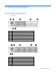
Component identification Front panel components • SFF model Item Description 1 Quick release levers (2) 2 Systems Insight Display 3 Hard drive bays 4 SATA optical drive bay 5 Video connector 6 USB connectors (2) • SFF model with optional hard drive cage Item Description 1 Quick release levers (2) 2 Systems Insight Display 3 Hard drive bays 4 Hard drive bays (optional) 5 Video connector Component identification 7
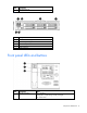
Item Description 6 USB connectors (2) • LFF model Item Description 1 Quick release levers (2) 2 Systems Insight Display 3 Hard drive bays 4 USB connectors (2) 5 Video connector Front panel LEDs and buttons Item Description Status 1 UID LED and button Blue = Activated Flashing blue = System being remotely managed Off = Deactivated Component identification 8
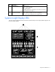
Item Description Status 2 System health LED Green = Normal Amber = System degraded. Red = System critical. To identify components in degraded or critical state, see "Systems Insight Display LEDs (on page 9)." 3 Power On/Standby button and system power LED Green = System on Amber = System in standby, but power is still applied Off = Power cord not attached or power supply failure Systems Insight Display LEDs The HP Systems Insight Display LEDs represent the system board layout.
Item Description Status 1 NIC link/activity LED Green = Network link Flashing green = Network link and activity Off = No link to network. If the power is off, view the rear panel RJ-45 LEDs for status ("Rear panel LEDs and buttons" on page 12) 2 Power cap To determine Power cap status, see "Systems Insight Display LED combinations (on page 10).
Systems Insight Display Health LED LED and color Power supply (amber) Red System power LED Status Amber • • • Power supply (amber) Amber Green • • • • Only one power supply is installed and that power supply is in standby. Power supply fault System board fault Redundant power supply is installed and only one power supply is functional. AC power cord is not plugged into redundant power supply.
10 Video connector 11 NIC 1 connector 12 NIC 2 connector 13 Mouse connector 14 Keyboard connector 15 Serial connector 16 iLO 2 connector 17 NIC 3 connector 18 NIC 4 connector Rear panel LEDs and buttons Item Description Status 1 Power supply LED Green = Normal Off = System is off or power supply has failed 2 UID LED/button Blue = Activated Flashing blue = System being managed remotely Off = Deactivated 3 NIC/iLO 2 activity Green = Network activity LED Flashing green = Network ac
Primary Secondary (slot - form factor) PCIe riser (slot - form factor) slot description PCIe x16 riser slot description PCIe/PCI-X riser slot description 2 - HL/FH 5 - LP PCIe x8 (4,1) — PCIe x16 (8,4,1) 3 - HL/FH 6 - LP PCIe x8 (4,1) — PCIe x8 (4,1) Notes: • "Primary" denotes the risers are installed in the primary riser connector. • "Secondary" denotes the risers are installed in the secondary riser connector. • FL/FH denotes full-length, full-height.
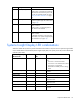
Item Description 1 Processor 2 DIMM slots 2 SAS power connector A 3 SAS power connector B 4 Front I/O connector 5 SATA optical drive connector 6 Internal USB connector 7 System battery 8 Power supply backplane connector 9 NMI jumper 10 System maintenance switch 11 Processor socket 2 12 Primary riser connector 13 SD card slot 14 TPM connector 15 Processor socket 1 (populated) 16 Processor 1 DIMM slots 17 Secondary riser connector 18 SAS connector A 19 SAS connector B 2
Position Default Function S3 Off Reserved S4 Off Reserved S5 Off Off = Power-on password is enabled. On = Power-on password is disabled. S6 Off Off = No function On = Clear NVRAM S7 — Reserved S8 — Reserved S9 — Reserved S10 — Reserved When the system maintenance switch position 6 is set to the On position, the system is prepared to erase all system configuration settings from both CMOS and NVRAM. CAUTION: Clearing CMOS and/or NVRAM deletes configuration information.
DIMM slot locations DIMM slots are numbered sequentially (1 through 9) for each processor. The supported AMP modes use the letter assignments for population guidelines.
• Optional SFF device bay numbering • LFF device bay numbering SAS and SATA hard drive LEDs Item Description 1 Fault/UID LED (amber/blue) 2 Online LED (green) Component identification 17
SAS and SATA hard drive LED combinations Online/activity LED (green) Fault/UID LED (amber/blue) Interpretation On, off, or flashing Alternating amber and The drive has failed, or a predictive failure alert has been blue received for this drive; it also has been selected by a management application. On, off, or flashing Steadily blue The drive is operating normally, and it has been selected by a management application.
Status On = AC power is connected. Off = AC power is disconnected. Missing = Riser is not installed and power might be connected. Battery pack LEDs Item ID Color Description 1 Green System Power LED. This LED glows steadily when the system is powered up and 12 V system power is available. This power supply is used to maintain the battery charge and provide supplementary power to the cache microcontroller.
Item ID Color Description 2 Green Auxiliary Power LED. This LED glows steadily when 3.3V auxiliary voltage is detected. The auxiliary voltage is used to preserve BBWC data and is available any time that the system power cords are connected to a power supply. 3 Amber Battery Health LED. To interpret the illumination patterns of this LED, see the following table. 4 Green BBWC Status LED. To interpret the illumination patterns of this LED, see the following table.
The only two valid fan configurations are listed in the following table. Configuration Fan bay 1 Fan bay 2 Fan bay 3 Fan bay 4 Fan bay 5 Fan bay 6 1 processor Fan Fan Fan Fan Fan blank Fan blank 2 processors Fan Fan Fan Fan Fan Fan For a single-processor configuration, four fans and two blanks are required in specific fan bays for redundancy. A fan failure or missing fan causes all fans to spin at high speed. A second fan failure or missing fan causes an orderly shutdown of the server.
Operations Power up the server To power up the server, press the Power On/Standby button. Power down the server WARNING: To reduce the risk of personal injury, electric shock, or damage to the equipment, remove the power cord to remove power from the server. The front panel Power On/Standby button does not completely shut off system power. Portions of the power supply and some internal circuitry remain active until AC power is removed.
3. After performing the installation or maintenance procedure, slide the server back into the rack, and then press the server firmly into the rack to secure it in place. WARNING: To reduce the risk of personal injury, be careful when pressing the server rail-release latches and sliding the server into the rack. The sliding rails could pinch your fingers.
1. Power down the server if performing a non-hot-plug installation or maintenance procedure ("Power down the server" on page 22). 2. Extend the server from the rack (on page 22). 3. Use the T-15 Torx screwdriver attached to the rear of the server to loosen the security screw on the hood latch. 4. Lift up on the hood latch handle, and then remove the access panel. Install the access panel 1. Place the access panel on top of the server with the hood latch open.
2. Open the cable management arm. Cable management arm with right-hand swing NOTE: To access some components, you may need to remove the cable management arm. To access the product rear panel components, open the cable management arm: 1. Power down the server (on page 22). 2. Swing open the cable management arm. 3. Remove the cables from the cable trough. 4. Remove the cable management arm.
Remove the PCI riser cage CAUTION: To prevent damage to the server or expansion boards, power down the server and remove all AC power cords before removing or installing the PCI riser cage. 1. Power down the server (on page 22). 2. Extend the server from the rack (on page 22). 3. Remove the access panel (on page 23). 4. Remove the PCI riser cage. Install the PCI riser cage 1. Install the PCI riser cage 2. Install the access panel (on page 24).
3. Install the server into the rack. 4. Power up the server (on page 22). Remove the air baffle CAUTION: For proper cooling do not operate the server without the access panel, baffles, expansion slot covers, or blanks installed. If the server supports hot-plug components, minimize the amount of time the access panel is open. 1. Power down the server (on page 22). 2. Extend or remove the server from the rack ("Extend the server from the rack" on page 22). 3. Remove the access panel (on page 23). 4.
Setup Optional installation services Delivered by experienced, certified engineers, HP Care Pack services help you keep your servers up and running with support packages tailored specifically for HP ProLiant systems. HP Care Packs let you integrate both hardware and software support into a single package. A number of service level options are available to meet your needs.
Optimum environment When installing the server in a rack, select a location that meets the environmental standards described in this section. Space and airflow requirements To allow for servicing and adequate airflow, observe the following space and airflow requirements when deciding where to install a rack: • Leave a minimum clearance of 63.5 cm (25 in) in front of the rack. • Leave a minimum clearance of 76.2 cm (30 in) behind the rack. • Leave a minimum clearance of 121.
Temperature requirements To ensure continued safe and reliable equipment operation, install or position the system in a well-ventilated, climate-controlled environment. The maximum recommended ambient operating temperature (TMRA) for most server products is 35°C (95°F). The temperature in the room where the rack is located must not exceed 35°C (95°F).
Because of the high ground-leakage currents associated with multiple servers connected to the same power source, HP recommends the use of a PDU that is either permanently wired to the building’s branch circuit or includes a nondetachable cord that is wired to an industrial-style plug. NEMA locking-style plugs or those complying with IEC 60309 are considered suitable for this purpose. Using common power outlet strips for the server is not recommended.
CAUTION: Always plan the rack installation so that the heaviest item is on the bottom of the rack. Install the heaviest item first, and continue to populate the rack from the bottom to the top. 1. Install the server and cable management arm into the rack. For more information, see the installation instructions that ship with the 2U Quick Deploy Rail System. 2. Connect peripheral devices to the server.For connector identification information, see Rear panel components (on page 11) in this guide.
6. Connect the power cord to the AC power source. WARNING: To reduce the risk of electric shock or damage to the equipment: • Do not disable the power cord grounding plug. The grounding plug is an important safety feature. • Plug the power cord into a grounded (earthed) electrical outlet that is easily accessible at all times. • Unplug the power cord from the power supply to disconnect power to the equipment. • Do not route the power cord where it can be walked on or pinched by items placed against it.
To configure these utilities manually: • Press the F8 key when prompted during the array controller initialization to configure the array controller using ORCA. • Press the F9 key when prompted during the boot process to change the server settings using RBSU. The system is set up by default for the English language. For more information on the automatic configuration, refer to the HP ROM-Based Setup Utility User Guide located on the Documentation CD.
Hardware options installation Introduction If more than one option is being installed, read the installation instructions for all the hardware options and identify similar steps to streamline the installation process. WARNING: To reduce the risk of personal injury from hot surfaces, allow the drives and the internal system components to cool before touching them. CAUTION: To prevent damage to electrical components, properly ground the server before beginning any installation procedure.
6. Open the heatsink retaining bracket, and then remove the processor blank. CAUTION: The pins on the processor socket are very fragile. Any damage to them may require replacing the system board. CAUTION: Failure to completely open the processor locking lever prevents the processor from seating during installation, leading to hardware damage. 7. Open the processor locking lever and the processor socket retaining bracket. Do not remove the processor socket cover.
8. If the processor has separated from the installation tool, carefully re-insert the processor in the tool. Handle the processor by the edges only, and do not touch the bottom of the processor, especially the contact area.
9. Align the processor installation tool with the socket, and then install the processor. THE PINS ON THE SYSTEM BOARD ARE VERY FRAGILE AND EASILY DAMAGED. CAUTION: THE PINS ON THE SYSTEM BOARD ARE VERY FRAGILE AND EASILY DAMAGED. To avoid damage to the system board: • Never install or remove a processor without using the processor installation tool. • Do not touch the processor socket contacts. • Do not tilt or slide the processor when lowering the processor into the socket.
10. Press the tabs on the processor installation tool to separate it from the processor, and then remove the tool. 11. Close the processor socket retaining bracket and the processor locking lever. The processor socket cover is automatically ejected. Remove the cover. CAUTION: Be sure to close the processor socket retaining bracket before closing the processor locking lever. The lever should close without resistance.
CAUTION: After the cover is removed, do not touch the thermal interface media. 13. Install the heatsink.
14. Close the heatsink retaining bracket. 15. Remove the fan blanks in bays 5 and 6. For fan location and numbering information, see "Hot-plug fans (on page 20)" or the label attached to the access panel. 16. Install the fans into bays 5 and 6. 17. Install the air baffle ("Remove the air baffle" on page 27). 18. Install the PCI riser cage. 19. Install the access panel (on page 24). 20. Install the server into the rack ("Installing the server into the rack" on page 31). 21.
IMPORTANT: This server does not support mixing RDIMMs and UDIMMs. Attempting to mix these two types causes the server to halt during BIOS initialization. The memory subsystem in this server can support RDIMMs or UDIMMs. Both types are referred to as DIMMs when the information applies to both types. When specified as RDIMM or UDIMM, the information applies to that type only. All memory installed in the server must be the same type.
DIMM identification IMPORTANT: This server does not support mixing RDIMMs and UDIMMs. Attempting to mix these two types causes the server to halt during BIOS initialization. The memory subsystem may be populated with either RDIMMs or UDIMMs, but mixing the two types is not supported. To determine DIMM characteristics, use the label attached to the DIMM and the following illustration and table.
• Lockstep—provides enhanced protection while making all installed memory available to the operating system. The server can continue to function if a single- or multi-bit memory failure within a single DRAM device occurs. Advanced Memory Protection options are configured in RBSU. If the requested AMP mode is not supported by the installed DIMM configuration, the server boots in Advanced ECC mode. For more information, see "HP ROM-Based Setup Utility (on page 66).
Lockstep mode uses channel 1 and channel 2. Channel 3 is not populated. Because channel 3 cannot be populated when using Lockstep mode, the maximum memory capacity is lower than Advanced ECC mode. Memory performance with Advanced ECC is also slightly higher. General DIMM slot population guidelines Observe the following guidelines for all AMP modes: • Populate DIMM slots for a processor only if the processor is installed.
Mirrored Memory population guidelines For Mirrored Memory mode configurations, observe the following guidelines: • Observe the general DIMM slot population guidelines (on page 45). • Always install DIMMs in channels 1 and 2 for each installed processor. • Do not install DIMMs in channel 3 for any processor. • DIMMs installed on channel 1 and channel 2 of an installed processor must be identical. • In multi-processor configurations, each processor must have a valid Mirrored Memory configuration.
Lockstep Memory population guidelines For Lockstep memory mode configurations, observe the following guidelines: • Observe the general DIMM slot population guidelines (on page 45). • Always install DIMMs in channels 1 and 2 for each installed processor. • Do not install DIMMs in channel 3 for any processor. • DIMM configuration on channel 1 and channel 2 of a processor must be identical. • In multi-processor configurations, each processor must have a valid Lockstep Memory configuration.
Installing a DIMM CAUTION: To avoid damage to the hard drives, memory, and other system components, the air baffle, drive blanks, and access panel must be installed when the server is powered up. 1. Power down the server (on page 22). 2. Extend the server from the rack (on page 22). 3. Remove the access panel (on page 23). 4. Remove the air baffle. 5. Open the DIMM slot latches. 6. Install the DIMM. 7. Install the air baffle ("Remove the air baffle" on page 27). 8.
Installing a hot-plug SAS hard drive 1. Remove the SAS hard drive blank. 2. Prepare the hard drive. 3. Install the hard drive. 4. Determine the status of the hard drive from the hot-plug SAS hard drive LED combinations ("SAS and SATA hard drive LED combinations" on page 18).
CAUTION: For proper cooling do not operate the server without the access panel, baffles, expansion slot covers, or blanks installed. If the server supports hot-plug components, minimize the amount of time the access panel is open. 1. Determine the status of the hard drive from the hot-plug SAS hard drive LED combinations ("SAS and SATA hard drive LED combinations" on page 18). 2. Back up all server data on the hard drive. 3. Remove the hard drive. Optical drive option 1.
5. Slide the optical drive into the drive bay. 6. Connect the power and data cable to the system board. The air baffle is not shown for clarity. 7. Connect the power and data cable to the optical drive. 8. Install the access panel (on page 24).
9. Power up the server (on page 22). Redundant hot-plug power supply option CAUTION: To prevent improper cooling and thermal damage, do not operate the server unless all bays are populated with either a component or a blank. 1. Access the product rear panel (on page 24). 2. Remove the power supply blank. WARNING: To reduce the risk of personal injury from hot surfaces, allow the power supply or power supply blank to cool before touching it. 3. Install the power supply in the power supply bay. 4.
5. Route the power cord through the power cord anchor or cable management arm. 6. Reposition the cable management arm into the operating position. 7. Connect the power cord to the power source. 8. Be sure that the power supply LED is green ("Rear panel LEDs and buttons" on page 12). 9. Verify that the corresponding power supply LED on the SID is green. Expansion board options The server supports PCI, PCI-X, and PCI Express expansion boards.
o To remove slot covers 2 and 3, lift up on the latch, remove the latch, and then remove the cover. o To remove slot covers 5 and 6, push down on the latch, rotate the latch down, and then remove the cover. Installing a half-length expansion board 1. Power down the server (on page 22). 2. Extend the server from the rack (on page 22). 3. Remove the access panel (on page 23). 4. Remove the PCI riser cage (on page 26). 5.
7. Connect any required internal or external cables to the expansion board. See the documentation that ships with the expansion board. 8. Install the PCI riser cage. 9. Install the access panel (on page 24). Installing a full-length expansion board 1. Power down the server (on page 22). 2. Extend the server from the rack (on page 22). 3. Remove the access panel (on page 23). 4. Remove the PCI riser cage (on page 26). 5.
9. Close the full-length expansion board retainer. 10. Connect any required internal or external cables to the expansion board. See the documentation that ships with the expansion board. 11. Install the PCI riser cage. 12. Install the access panel (on page 24). PCI riser board option CAUTION: For proper cooling do not operate the server without the access panel, baffles, expansion slot covers, or blanks installed.
5. Install the optional riser board. 6. Install any expansion boards. ("Expansion board options" on page 53) 7. Install the PCI riser cage. 8. Install the access panel (on page 24). 9. Install the server into the rack. 10. Power up the server (on page 22). Hard drive cage option Installation of a SAS expander card or an additional SAS controller option is required to support the hard drive cage option. 1. Power down the server (on page 22). 2. Extend the server from the rack (on page 22). 3.
6. Remove the two primary hard drive retaining screws and slide the cage forward. 7. Install the optional hard drive cage. 8. Install the hard drives and hard drive blanks ("Hot-plug SAS hard drive options" on page 48, "Optical drive option" on page 50). 9. Remove the PCI riser cage (on page 26). 10. Install the optional SAS controller. For installation instructions, see the documentation that ships with the SAS controller option. 11. Remove the air baffle (on page 27).
12. Connect one end of the power cable to the SAS backplane and the other end to the system board. 13. Install the primary hard drive cage. 14. Connect one end of each SAS cable to the SAS controller. For connector information, see the documentation that ships with the SAS controller option. 15. Install the air baffle ("Remove the air baffle" on page 27). 16. Connect the remaining end of each SAS cable to the backplane, 17. Install the PCI riser cage. 18. Install the access panel (on page 24).
HP Trusted Platform Module option Use these instructions to install and enable a TPM on a supported server. This procedure includes three sections: 1. Installing the Trusted Platform Module board. 2. Retaining the recovery key/password (on page 62). 3. Enabling the Trusted Platform Module (on page 62). Enabling the TPM requires accessing the ROM-Based Setup Utility (RBSU) ("HP ROM-Based Setup Utility" on page 66). For more information about RBSU, see the HP website (http://www.hp.
4. Remove the access panel (on page 23). 5. Remove the PCI riser cage (on page 26). 6. Remove the air baffle (on page 27). CAUTION: Any attempt to remove an installed TPM from the system board breaks or disfigures the TPM security rivet. Upon locating a broken or disfigured rivet on an installed TPM, administrators should consider the system compromised and take appropriate measures to ensure the integrity of the system data. 7. Install the TPM board. Press down on the connector to seat the board.
Retaining the recovery key/password The recovery key/password is generated during BitLocker™ setup, and can be saved and printed after BitLocker™ is enabled. When using BitLocker™, always retain the recovery key/password. The recovery key/password is required to enter Recovery Mode after BitLocker™ detects a possible compromise of system integrity.
Cabling SAS hard drive cabling Optical drive cabling Cabling 63
BBWC battery cabling Cabling 64
Configuration and utilities Configuration tools SmartStart software SmartStart is a collection of software that optimizes single-server setup, providing a simple and consistent way to deploy server configuration. SmartStart has been tested on many ProLiant server products, resulting in proven, reliable configurations.
refer to the SmartStart Scripting Toolkit User Guide on the HP website (http://h18004.www1.hp.com/products/servers/management/toolkit/documentation.html).
NOTE: If the boot drive is not empty or has been written to in the past, ORCA does not automatically configure the array. You must run ORCA to configure the array settings. Drives installed Drives used RAID level 1 1 RAID 0 2 2 RAID 1 3, 4, 5, or 6 3, 4, 5, or 6 RAID 5 More than 6 0 None To change any ORCA default settings and override the auto-configuration process, press the F8 key when prompted. By default, the auto-configuration process configures the system for the English language.
7. Press the Esc key to exit the current menu or press the F10 key to exit RBSU. For more information on mirrored memory, see the white paper on the HP website (http://h18000.www1.hp.com/products/servers/technology/memoryprotection.html). Configuring lockstep memory To configure Lockstep memory: 1. Install the required DIMMs ("Installing a DIMM" on page 48). 2. Access RBSU by pressing the F9 key during power-up when the prompt is displayed. 3. Select System Options. 4.
The utility also provides support for the following functions: • Reconfiguring one or more logical drives • Viewing the current logical drive configuration • Deleting a logical drive configuration • Setting the controller to be the boot controller If you do not use the utility, ORCA will default to the standard configuration. For more information regarding array controller configuration, refer to the controller user guide.
ASR increases server availability by restarting the server within a specified time after a system hang or shutdown. At the same time, the HP SIM console notifies you by sending a message to a designated pager number that ASR has restarted the system. You can disable ASR from the HP SIM console or through RBSU. ROMPaq utility The ROMPaq utility enables you to upgrade the system firmware (BIOS). To upgrade the firmware, insert a ROMPaq USB Key into an available USB port and boot the system.
To access the Erase Utility, use the System Erase button on the home screen of the SmartStart CD ("SmartStart software" on page 65). Redundant ROM support The server enables you to upgrade or configure the ROM safely with redundant ROM support. The server has a single ROM that acts as two separate ROM images. In the standard implementation, one side of the ROM contains the current ROM program version, while the other side of the ROM contains a backup version.
Diagnostic tools HP Insight Diagnostics HP Insight Diagnostics is a proactive server management tool, available in both offline and online versions, that provides diagnostics and troubleshooting capabilities to assist IT administrators who verify server installations, troubleshoot problems, and perform repair validation. HP Insight Diagnostics Offline Edition performs various in-depth system and component testing while the OS is not running. To run this utility, launch the SmartStart CD.
Remote support and analysis tools HP Insight Remote Support software HP strongly recommends that you install HP Insight Remote Support software to complete the installation or upgrade of your product and to enable enhanced delivery of your HP Warranty, HP Care Pack Service, or HP contractual support agreement.
ProLiant Support Packs PSPs represent operating system-specific bundles of ProLiant optimized drivers, utilities, and management agents. Refer to the PSP website (http://h18000.www1.hp.com/products/servers/management/psp.html). Operating System Version Support For information about specific versions of a supported operating system, refer to the operating system support matrix (http://www.hp.com/go/supportos).
Troubleshooting Troubleshooting resources The HP ProLiant Servers Troubleshooting Guide provides procedures for resolving common problems and comprehensive courses of action for fault isolation and identification, error message interpretation, issue resolution, and software maintenance on ProLiant servers and server blades. This guide includes problem-specific flowcharts to help you navigate complex troubleshooting processes. To view the guide, select a language: • English (http://www.hp.
Symbols on equipment The following symbols may be placed on equipment to indicate the presence of potentially hazardous conditions. This symbol indicates the presence of hazardous energy circuits or electric shock hazards. Refer all servicing to qualified personnel. WARNING: To reduce the risk of injury from electric shock hazards, do not open this enclosure. Refer all maintenance, upgrades, and servicing to qualified personnel. This symbol indicates the presence of electric shock hazards.
WARNING: To reduce the risk of electric shock or damage to the equipment: • Do not disable the power cord grounding plug. The grounding plug is an important safety feature. • Plug the power cord into a grounded (earthed) electrical outlet that is easily accessible at all times. • Unplug the power cord from the power supply to disconnect power to the equipment. • Do not route the power cord where it can be walked on or pinched by items placed against it.
2. Record any error messages displayed by the system. 3. Remove all diskettes, CD-ROMs, DVD-ROMs, and USB drive keys. 4. Power down the server and peripheral devices if you will be diagnosing the server offline. If possible, always perform an orderly shutdown: a. Exit any applications. b. Exit the operating system. c. Power down the server (on page 22). 5. Disconnect any peripheral devices not required for testing (any devices not necessary to power up the server).
When requested to break the server down to the minimum configuration, uninstall the following components, if installed: • All additional DIMMs Leave only the minimum required to boot the server—either one DIMM or a pair of DIMMs. For more information, see the memory guidelines in the server user guide. • All additional cooling fans, if applicable For the minimum fan configuration, see the server user guide.
Service notifications To view the latest service notifications, refer to the HP website (http://www.hp.com/go/bizsupport). Select the appropriate server model, and then click the Troubleshoot a Problem link on the product page. Server health LEDs Some servers have an internal health LED and an external health LED, while other servers have a single system health LED. The system health LED provides the same functionality as the two separate internal and external health LEDs.
General diagnosis flowchart The General diagnosis flowchart provides a generic approach to troubleshooting. If you are unsure of the problem, or if the other flowcharts do not fix the problem, use the following flowchart. Item See 1 "Symptom information (on page 77)" 2 "Loose connections (on page 79)" 3 "Service notifications (on page 80)" 4 The most recent version of a particular server or option firmware is available on the HP Support website (http://www.hp.com/support).
Item See 5 "General memory problems are occurring" in the HP ProLiant Servers Troubleshooting Guide located on the Documentation CD or see "Troubleshooting resources (on page 75)" 6 Server maintenance and service guide, located on the Documentation CD or the HP website (http://www.hp.
Server power-on problems flowchart Symptoms: • The server does not power on. • The system power LED is off or amber.
• The external health LED is red or amber. • The internal health LED is red or amber. NOTE: For the location of server LEDs and information on their statuses, refer to the server documentation.
Troubleshooting 85
POST problems flowchart Symptoms: • Server does not complete POST NOTE: The server has completed POST when the system attempts to access the boot device.
Item See 13 • • "Server information you need" in the HP ProLiant Servers Troubleshooting Guide located on the Documentation CD or see "Troubleshooting resources (on page 75)" "Operating system information you need" in the HP ProLiant Servers Troubleshooting Guide located on the Documentation CD or see "Troubleshooting resources (on page 75)" Troubleshooting 87
OS boot problems flowchart Symptoms: • Server does not boot a previously installed operating system • Server does not boot SmartStart Possible causes: • Corrupted operating system • Hard drive subsystem problem • Incorrect boot order setting in RBSU Item See 1 HP ROM-Based Setup Utility User Guide (http://www.hp.
Server fault indications flowchart Symptoms: • Server boots, but a fault event is reported by Insight Management Agents • Server boots, but the internal health LED, external health LED, or component health LED is red or amber NOTE: For the location of server LEDs and information on their statuses, refer to the server documentation.
Possible causes: • Improperly seated or faulty internal or external component • Unsupported component installed • Redundancy failure • System overtemperature condition Item See 1 • • "Integrated Management Log (on page 72)" or in the HP ProLiant Servers Troubleshooting Guide located on the Documentation CD or see "Troubleshooting resources (on page 75)" "Event list error messages" in the HP ProLiant Servers Troubleshooting Guide located on the Documentation CD or see "Troubleshooting resources
POST error messages and beep codes For a complete listing of error messages, refer to the "POST error messages" in the HP ProLiant Servers Troubleshooting Guide located on the Documentation CD or on the HP website (http://www.hp.com/support).
WARNING: To avoid potential problems, ALWAYS read the warnings and cautionary information in the server documentation before removing, replacing, reseating, or modifying system components.
Battery replacement If the server no longer automatically displays the correct date and time, you may need to replace the battery that provides power to the real-time clock. WARNING: The computer contains an internal lithium manganese dioxide, a vanadium pentoxide, or an alkaline battery pack. A risk of fire and burns exists if the battery pack is not properly handled. To reduce the risk of personal injury: • • • • Do not attempt to recharge the battery.
Regulatory compliance notices Regulatory compliance identification numbers For the purpose of regulatory compliance certifications and identification, this product has been assigned a unique regulatory model number. The regulatory model number can be found on the product nameplate label, along with all required approval markings and information. When requesting compliance information for this product, always refer to this regulatory model number.
radio communications. However, there is no guarantee that interference will not occur in a particular installation. If this equipment does cause harmful interference to radio or television reception, which can be determined by turning the equipment off and on, the user is encouraged to try to correct the interference by one or more of the following measures: • Reorient or relocate the receiving antenna. • Increase the separation between the equipment and receiver.
This Class A digital apparatus meets all requirements of the Canadian Interference-Causing Equipment Regulations. Cet appareil numérique de la classe A respecte toutes les exigences du Règlement sur le matériel brouilleur du Canada. Class B equipment This Class B digital apparatus meets all requirements of the Canadian Interference-Causing Equipment Regulations. Cet appareil numérique de la classe B respecte toutes les exigences du Règlement sur le matériel brouilleur du Canada.
This symbol on the product or on its packaging indicates that this product must not be disposed of with your other household waste. Instead, it is your responsibility to dispose of your waste equipment by handing it over to a designated collection point for the recycling of waste electrical and electronic equipment.
Class B equipment Chinese notice Class A equipment Laser compliance This product may be provided with an optical storage device (that is, CD or DVD drive) and/or fiber optic transceiver. Each of these devices contains a laser that is classified as a Class 1 Laser Product in accordance with US FDA regulations and the IEC 60825-1. The product does not emit hazardous laser radiation. Each laser product complies with 21 CFR 1040.10 and 1040.11 except for deviations pursuant to Laser Notice No.
For more information about battery replacement or proper disposal, contact an authorized reseller or an authorized service provider. Taiwan battery recycling notice The Taiwan EPA requires dry battery manufacturing or importing firms in accordance with Article 15 of the Waste Disposal Act to indicate the recovery marks on the batteries used in sales, giveaway or promotion. Contact a qualified Taiwanese recycler for proper battery disposal.
Electrostatic discharge Preventing electrostatic discharge To prevent damaging the system, be aware of the precautions you need to follow when setting up the system or handling parts. A discharge of static electricity from a finger or other conductor may damage system boards or other static-sensitive devices. This type of damage may reduce the life expectancy of the device. To prevent electrostatic damage: • Avoid hand contact by transporting and storing products in static-safe containers.
Specifications Environmental specifications Specification Value Temperature range* Operating 10°C to 35°C (50°F to 95°F) Shipping -30°C to 50°C (-22°F to 122°F) Storage -30°C to 60°C (-22°F to 140°F) Maximum wet bulb temperature 28°C (82.4°F) Relative humidity (noncondensing)** Operating 10% to 90% Non-operating 5% to 95% * All temperature ratings shown are for sea level. An altitude derating of 1°C per 300 m (1.8°F per 1,000 ft) to 3048 m (10,000 ft) is applicable. No direct sunlight allowed.
Rated input current 10 A at 100 VAC 4.
Rated steady-state power 460 W at 100V to 120V AC input 460 W at 200V to 240V AC input Maximum peak power 460 W at 100V to 120V AC input 460 W at 200V to 240V AC input Specifications 103
Technical support Before you contact HP Be sure to have the following information available before you call HP: • Technical support registration number (if applicable) • Product serial number • Product model name and number • Product identification number • Applicable error messages • Add-on boards or hardware • Third-party hardware or software • Operating system type and revision level HP contact information For the name of the nearest HP authorized reseller: • See the Contact HP worldwi
• Optional—Parts for which customer self repair is optional. These parts are also designed for customer self repair. If, however, you require that HP replace them for you, there may or may not be additional charges, depending on the type of warranty service designated for your product. NOTE: Some HP parts are not designed for customer self repair. In order to satisfy the customer warranty, HP requires that an authorized service provider replace the part.
Riparazione da parte del cliente Per abbreviare i tempi di riparazione e garantire una maggiore flessibilità nella sostituzione di parti difettose, i prodotti HP sono realizzati con numerosi componenti che possono essere riparati direttamente dal cliente (CSR, Customer Self Repair). Se in fase di diagnostica HP (o un centro di servizi o di assistenza HP) identifica il guasto come riparabile mediante un ricambio CSR, HP lo spedirà direttamente al cliente per la sostituzione.
CSR-Teile werden abhängig von der Verfügbarkeit und vom Lieferziel am folgenden Geschäftstag geliefert. Für bestimmte Standorte ist eine Lieferung am selben Tag oder innerhalb von vier Stunden gegen einen Aufpreis verfügbar. Wenn Sie Hilfe benötigen, können Sie das HP technische Support Center anrufen und sich von einem Mitarbeiter per Telefon helfen lassen. Den Materialien, die mit einem CSR-Ersatzteil geliefert werden, können Sie entnehmen, ob das defekte Teil an HP zurückgeschickt werden muss.
Para obtener más información acerca del programa de Reparaciones del propio cliente de HP, póngase en contacto con su proveedor de servicios local. Si está interesado en el programa para Norteamérica, visite la página web de HP siguiente (http://www.hp.com/go/selfrepair). Customer Self Repair Veel onderdelen in HP producten zijn door de klant zelf te repareren, waardoor de reparatieduur tot een minimum beperkt kan blijven en de flexibiliteit in het vervangen van defecte onderdelen groter is.
Opcional – Peças cujo reparo feito pelo cliente é opcional. Essas peças também são projetadas para o reparo feito pelo cliente. No entanto, se desejar que a HP as substitua, pode haver ou não a cobrança de taxa adicional, dependendo do tipo de serviço de garantia destinado ao produto. OBSERVAÇÃO: Algumas peças da HP não são projetadas para o reparo feito pelo cliente. A fim de cumprir a garantia do cliente, a HP exige que um técnico autorizado substitua a peça.
Technical support 110
Technical support 111
Acronyms and abbreviations ABEND abnormal end ACU Array Configuration Utility AMP Advanced Memory Protection ASR Automatic Server Recovery BBWC battery-backed write cache CSA Canadian Standards Association CSR Customer Self Repair DDR double data rate ECC error checking and correcting IEC International Electrotechnical Commission iLO Integrated Lights-Out IML Integrated Management Log Acronyms and abbreviations 112
ISEE Instant Support Enterprise Edition NFPA National Fire Protection Association NMI non-maskable interrupt NVRAM non-volatile memory ORCA Option ROM Configuration for Arrays PCI peripheral component interface PCIe peripheral component interconnect express PCI-X peripheral component interconnect extended POST Power-On Self Test PPM processor power module PSP ProLiant Support Pack RBSU ROM-Based Setup Utility RDIMM Registered Dual In-line Memory Module RDP Rapid Deployment Pack Acronyms and ab
SAS serial attached SCSI SDDC Single Device Data Correction SDRAM synchronous dynamic RAM SFF small form-factor SIM Systems Insight Manager SMTP Simple Mail Transfer Protocol SNMP Simple Network Management Protocol TMRA recommended ambient operating temperature TPM trusted platform module UDIMM Unregistered Dual In-Line Memory Module UID unit identification UPS uninterruptible power system USB universal serial bus VCA Version Control Agent Acronyms and abbreviations 114
Index A D access panel 23, 24 air baffle 27 Array Configuration Utility (ACU) 68 ASR (Automatic Server Recovery) 69 authorized reseller 104 auto-configuration process 66 Automatic Server Recovery (ASR) 69 diagnostic tools 69, 70, 72 diagnostics utility 72 DIMM installation guidelines 45 DIMM slot locations 16 DIMMs 16, 41, 42, 43, 67 drive LEDs 17, 18 drivers 73 B E battery 15, 93, 98 battery cabling for BBWC 64 battery pack LEDs 19 battery-backed write cache (BBWC) 19 BIOS Serial Console 67 BIOS upgr
health LEDs 8, 15, 80 help resources 104 HP Insight Diagnostics 72 HP technical support 104 I identification number 94 iLO (Integrated Lights-Out) 70 iLO 2 connector 11 IML (Integrated Management Log) 72 Important Safety Information document 75 Insight Diagnostics 72, 73 installation services 28 installation, server options 31, 35 installing hardware 35 Integrated Lights-Out (iLO) 70 Integrated Management Log (IML) 72 internal USB connector 71 J Japanese notice 97 K keyboard connector 11 Korean notices 9
resetting the system 15 ROM redundancy 71 ROMPaq utility 70, 71 S safety considerations 31, 75 SAS drive numbers 18 SAS hard drive LEDs 17, 18 scripted installation 65 serial connector 11 serial number 69 series number 94 server fault indications flowchart 89 server features and options 35 service notifications 80 shipping carton contents 31 SmartStart autorun menu 65 SmartStart Scripting Toolkit 65 SmartStart, overview 65 specifications 101 specifications, environmental 101 specifications, power 101 start