Pedestal Kit Installation Guide for HP Integrity rx2800 i2 and HP Proliant DL380 G6 & DL385 G6 Servers HP Part Number: AM251-9000A Published: January 2010 Edition: 1
© Copyright 2010 Hewlett-Packard Development Company, L.P. Legal Notices The information contained herein is subject to change without notice. The only warranties for HP products and services are set forth in the express warranty statements accompanying such products and services. Nothing herein should be construed as constituting an additional warranty. HP shall not be liable for technical or editorial errors or omissions contained herein.
Table of Contents Abstract...............................................................................................................................5 Intended audience..................................................................................................................................5 1 Important warnings........................................................................................................7 Electricity......................................................................
List of Figures 2-1 2-2 2-3 2-4 2-5 2-6 2-7 3-1 3-2 3-3 3-4 4-1 4-2 4-3 4-4 4-5 4 Removing the rails from the server.................................................................................................9 Front of server...............................................................................................................................10 Installing the pedestal bottom piece..............................................................................................
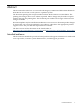
Abstract This document describes how to convert the HP Integrity rx2800 i2 and HP Proliant DL380 G6 & DL385 G6 servers from a rack system to a pedestal system. The document printing date and part number indicate the document’s current edition. The printing date changes when a new edition is printed. Minor changes may be made at reprint without changing the printing date. The document part number also changes when extensive changes are made.
1 Important warnings Electricity Electrical grounding WARNING! For your safety always connect the equipment to a grounded wall outlet. Always use a power cord with a properly grounded plug, such as the one provided with the equipment, or one in compliance with your national safety standards. This equipment can be disconnected from the power by removing the power cord from the power outlet. This means the equipment must be located close to an easily accessible power outlet.
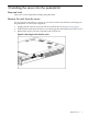
2 Installing the server into the pedestal kit Required tools There are no tools required for installing the pedestal kit. Remove the rails from the server If your server has rails when you receive it, you need to remove the rails before mounting it in the pedestal kit. To remove the component: 1. 2. 3. Slightly pull the rail lock away from the rail to unlock the rail. See Figure 2-1 (page 9). Slide the rail toward the front of the server to disengage the rail from the posts on the server.
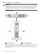
Attach the pedestal kit top and bottom IMPORTANT: In this document the server top, bottom, right and left always refer to the server as faced from the front with the server in a horizontal orientation. The pedestal kit components are referred to by their final position with the server in a vertical orientation. For example, the pedestal kit bottom attaches to the server left side. See Figure 2-2 (page 10) for the server and pedestal orientations.
NOTE: The bottom piece of the pedestal is taller than the server, so try to position the server so the right side (in the horizontal position) of the server hangs off the edge of the work surface by a few inches to allow the bottom piece to be attached to the server chassis. If that is not possible, then raise up the server approximately 3 inches from the work surface to allow the pedestal kit bottom piece to be attached to the server left side. To attach the components. 1.
Attach the bezel cover To attach the bezel cover: 1. 2. Attach the bezel cover to the front of the server starting from the bottom of the pedestal kit. Push the bezel cover into place against the pedestal kit top piece until the tabs on the bezel cover snap into place.
Attach the pedestal kit side pieces The pedestal kit right side piece attaches to the top of the server. The top cover of the server might have ventilation holes in it to allow for proper air flow and cooling. The right side piece of the pedestal kit also has ventilation holes in it to allow for the proper cooling and air flow. Follow these steps to attach the pedestal kit right side piece.
3. Secure the pedestal side by hand tightening the captive thumb screws on the rear of the server. Figure 2-6 Thumb screw locations Repeat these steps to install the left side piece.
Attach the pedestal feet The pedestal feet slide into the slots on the pedestal bottom, two on each side. The feet are all the same and can be mounted in any slot on the bottom piece of the pedestal kit.
3 Accessing internal components To access internal components on a pedestal-mounted server: 1. 2. Power down the server and remove all cables. Remove the pedestal kit feet. Figure 3-1 Removing the pedestal kit feet 3. 4. Lay the server on the left side (facing the front of the server). The right side of the pedestal kit (with the ventilation holes) should be facing up. Unscrew the captive thumbscrews on the rear of the pedestal kit for the right side pedestal kit piece.
Figure 3-2 Thumbscrew locations 5. Slide the right side pedestal kit piece toward the back of the server, and lift up on the piece to remove it from the pedestal.
6. Remove the server access panel. Figure 3-4 Access panel removal The server is ready for servicing. Once servicing is complete, do the following to put the pedestal kit back on the server. 1. 2. 3. 4. 5. 6. Close the access panel. Install the right side pedestal piece. Tighten the thumbscrews on the rear of the server. Stand the server up onto the bottom piece of the pedestal kit. Install the pedestal kit feet into the slots on the bottom of the pedestal kit. Connect the cables and restart the server.
4 Removing the server from the pedestal kit Required tools No tools are required for disassembling the pedestal kit. Power off the server and remove cables 1. 2. Power down the server using the instructions provided in the server service guide. Disconnect the power and LAN cables connected to the server. Removing the pedestal kit 1. Remove pedestal feet. Figure 4-1 Removing the pedestal kit feet 2.
Figure 4-2 Thumbscrew locations Figure 4-3 Removing the side piece 3. 22 Release the locking tabs behind the top corners of the bezel cover and remove the component.
Figure 4-4 Removing the bezel cover 4. Remove the pedestal top piece. a. With the server still in the vertical position, look at the left side of the server (server bottom) to locate the lock release tab. b. Press the lock release tab on the pedestal top piece away from the chassis to unlock the pedestal top piece from the server. See Figure 4-5 for the pedestal top and bottom piece lock release locations. Figure 4-5 Removing the pedestal top piece c. d. e. f.
5 Support and other resources Publishing history This table lists the publishing history of this document. Document Manufacturing Part Number Publication Date AM251-9000A January 2010 Related information The latest versions of these documents, including any updates, are posted at: http://www.hp.com/ go/Integrity_Servers-docs and http://www.hp.com/go/Proliant_Servers-docs. The Rack System /E User's Manual can be found at: http://www.hp.com under Enterprise Rack & Power Products.
Index A W access panel removal, 19 warnings electrical, 7 metallic particulate contamination, 7 static electricity, 7 B bezel cover attaching, 12 removal, 22 Z zinc whiskers (see metallic particulate contamination) E electricity grounding, 7 static, 7 I internal components accessing, 17 M metallic particulate contamination, 7 P pedestal bottom attaching, 10 removal, 23 pedestal feet attaching, 15 removal, 17, 21 pedestal side removal, 18 pedestal sides attaching, 13 pedestal top attaching, 10 remov
*AM251-9000A* Printed in the US