HP ProLiant DL385 Server User Guide August 2006 (Fourth Edition) Part Number 376536-004
© Copyright 2004, 2005, 2006 Hewlett-Packard Development Company, L.P. The information contained herein is subject to change without notice. The only warranties for HP products and services are set forth in the express warranty statements accompanying such products and services. Nothing herein should be construed as constituting an additional warranty. HP shall not be liable for technical or editorial errors or omissions contained herein. Microsoft, Windows, and Windows NT are U.S.
Contents Server component identification...................................................................................................... 7 Front panel components ............................................................................................................................. 8 Front panel LEDs and buttons ...................................................................................................................... 9 Rear panel components............................................
Installing the server into the rack................................................................................................................ 38 Powering up and configuring the server ..................................................................................................... 41 Installing the operating system................................................................................................................... 41 Registering the server.............................................
RILOE cabling (SCSI)...................................................................................................................... 77 Internal power cabling ................................................................................................................... 77 Server software and configuration utilities...................................................................................... 78 Configuration tools .........................................................................
Introduction to POST error messages .............................................................................................. 104 Battery replacement .................................................................................................................. 107 Electrostatic discharge ............................................................................................................... 108 Preventing electrostatic discharge .............................................................
Server component identification In this section Front panel components ............................................................................................................................ 8 Front panel LEDs and buttons ..................................................................................................................... 9 Rear panel components...........................................................................................................................
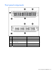
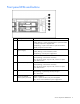
Front panel components Item SCSI model (top) SAS model (bottom) 1 Hard drive bays Hard drive bays 2 USB port USB port 3 Bay for tape drive or hard drive with tape drive blank — 4 Diskette drive bay Diskette drive bay 5 DVD/CD-ROM drive DVD/CD-ROM drive Server component identification 8
Front panel LEDs and buttons Item Description 1 Internal health LED Status Green = Normal Amber (flashing) = System degraded. Refer to system board LEDs to identify component in degraded state. Red (flashing) = System critical. Refer to system board LEDs to identify component in critical state.
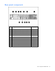
Rear panel components Item Description Connector color 1 PCI-X expansion slot 1, 64 bit/100 MHz, Bus A N/A 2 PCI-X expansion slot 2, 64 bit/100 MHz, Bus A N/A 3 PCI-X expansion slot 3, 64 bit/133 MHz, Bus B N/A 4 Serial connector Teal 5 iLO connector N/A 6 Mouse connector Green 7 Power cord connector N/A 8 Keyboard connector Purple 9 NIC 1 connector N/A 10 NIC 2 connector N/A 11 USB connectors (2) Black 12 Video connector Blue Server component identification 10
Rear panel LEDs and buttons Item Description LED color 1 RJ-45 activity LED Green Status On or flashing = Network activity Off = No network activity 2 RJ-45 link LED Green On = Linked to network Off = Not linked to network 3 UID LED button Blue On = Activated Flashing = System remotely managed Off = Deactivated 4 Power supply LED Green On = Power turned on and power supply functioning properly Off = One or more of the following conditions exists: • AC power unavailable • Power supply f
System board components Item Description 1 Smart Array 6i Cache Module option 2 PPM for processor 1 3 NMI header 4 PCI riser cage connector 5 DIMM slots (5-8) 6 Remote management connector 7 SCSI connector (port 2) * 8 Fan connector 9 DVD/CD-ROM drive system connector 10 Fan connector 11 SCSI connector (port 1) * 12 Fan connector 13 System maintenance switch 14 Diskette drive system connector 15 Power supply signal connector 16 Fan connector 17 System power connector 18
System maintenance switch Position Default Function S1 Off Off = iLO security is enabled. On = iLO security is disabled. S2 Off Off = System configuration can be changed. On = System configuration is locked. S3 Off Reserved S4 Off Reserved S5 Off Off = No function On = Clears power-on password and administrator password S6 Off Off = No function On = Clear NVRAM.
DIMM slots DIMM slots are numbered sequentially (1 through 8) and the paired banks are identified by the letters A, B, C, and D.
SCSI backplane components Item Description 1 Power button/LED connector 2 SCSI connector (port 2) 3 DVD/CD-ROM drive connector 4 SCSI connector (port 1) 5 Diskette drive connector 6 Power connector 7 USB connector 8 Diskette drive system connector 9 SCSI connector (used with a jumper cable in simplex mode or terminator board in duplex mode) 10 DVD/CD-ROM drive system connector Server component identification 15
SAS backplane components Item Description 1 Power button/LED connector 2 DVD/CD-ROM drive connector 3 DVD/CD-ROM drive system connector 4 SAS connector 5 Diskette drive system connector 6 Diskette drive connector 7 SAS connector 8 Power connector 9 USB connector System board LEDs Server component identification 16
Item LED description Status 1 Power good Green = Normal Off = Power failure 2 Riser interlock Amber = PCI riser cage not seated Off = PCI riser cage is seated 3 PPM 1 failure 4 System overtemperature Amber = PPM failure Off = Normal Amber = Cautionary or critical temperature level detected Off = Temperature OK 5 Processor 2 overtemperature Amber = Cautionary or critical temperature level detected Off = Temperature OK 6 Processor 2 failure Amber = Processor failure Off = Normal 7 Auxilia
System LEDs and internal health LED combinations When the internal health LED on the front panel illuminates either amber or red, the server is experiencing a health event. Combinations of illuminated system LEDs and the internal health LED indicate system status. The front panel health LEDs indicate only the current hardware status.
SCSI backplane LEDs Item LED description 1 SCSI configuration Status On = Simplex Off = Duplex 2 SCSI configuration error On = SCSI cabling or terminator configuration is incorrect Off = SCSI cabling or terminator configuration is correct Hot-plug SCSI hard drive LEDs Server component identification 19
Item LED description Status 1 Activity status On = Drive activity Flashing = High activity on the drive or drive is being configured as part of an array. Off = No drive activity 2 On = Drive is part of an array and is currently working. Online status Flashing = Drive is actively online. Off = Drive is offline.
Activity LED (1) Online LED Fault LED (2) (3) Interpretation Off Off One or more of the following conditions may exist: Off • The drive is not configured as part of an array • The drive is configured as part of an array, but it is a replacement drive that is not being accessed or being rebuilt yet • The drive is configured as an online spare If the drive is connected to an array controller, you may replace the drive online.
Online/activity LED Fault/UID LED (green) (amber/blue) Interpretation Flashing regularly (1 Hz) Do not remove the drive. Removing a drive may terminate the current operation and cause data loss. Amber, flashing regularly (1 Hz) The drive is part of an array that is undergoing capacity expansion or stripe migration, but a predictive failure alert has been received for this drive. To minimize the risk of data loss, do not replace the drive until the expansion or migration is complete.
Remote management connector The 30-pin remote management connector, located on the system board, is used to cable the RILOE II option. For more information, refer to "SAS RILOE II Cabling ("RILOE cabling (SAS)" on page 67)," "SCSI RILOE II Cabling ("RILOE cabling (SCSI)" on page 77)," or the Remote Insight Lights-Out Edition II User Guide on the Documentation CD.
Item Description Configuration 6 Fan 6 Primary 7 Fan 7 Primary 8 Fan 8 Redundant Hot-plug fan LED Status Green = Operating normally Amber = Failed Off = No power Power converter module LED Server component identification 24
Status Amber = Failed Off = Operating normally Battery-backed write cache LEDs NOTE: This feature applies only to SCSI models. Item LED color 1 Amber 2 Green For LED status information, refer to "Battery-backed write cache LED statuses (on page 25)." Battery-backed write cache LED statuses NOTE: This feature applies only to SCSI models.
Server status LED status Battery module status Server is off and is in data retention mode Amber = Flashing every User data held in the write cache is being 15 seconds backed up.
Server operations In this section Power up the server ................................................................................................................................ 27 Power down the server............................................................................................................................ 27 Extend the server from the rack ................................................................................................................ 28 Removing the access panel....
4. Press the Power On/Standby button to place the server in standby mode (2). When the server activates standby power mode, the system power LED changes to amber. 5. If the server is installed in a rack, locate the server by identifying the illuminated rear UID LED button. 6. Disconnect the power cords. The system is now without power. Extend the server from the rack 1. Pull down the quick release levers on each side of the server to release the server from the rack. 2.
3. After performing the installation or maintenance procedure, slide the server back into the rack: a. Press the server rail-release latches and slide the server fully into rack. b. Press the server firmly into the rack to secure it in place. Removing the access panel WARNING: To reduce the risk of personal injury from hot surfaces, allow the drives and the internal system components to cool before touching them. CAUTION: Do not operate the server for long periods with the access panel open or removed.
Access the product rear panel Cable management arm with left-hand swing To access the server rear panel, open the cable management arm. Cable management arm with right-hand swing NOTE: To access some components, you may need to remove the cable management arm. To access the product rear panel components, open the cable management arm: 1. Power down the server (on page 27). 2. Swing open the cable management arm. 3. Remove the cables from the cable trough. 4. Remove the cable management arm.
Removing the PCI riser cage CAUTION: To prevent damage to the server or expansion boards, power down the server and remove all AC power cords before removing or installing the expansion boards. 1. Power down the server (on page 27). 2. Extend the server from the rack, if applicable ("Extend the server from the rack" on page 28). 3. Remove the access panel ("Removing the access panel" on page 29). CAUTION: Always wear an antistatic wrist strap when working inside the server. 4.
1. Align the PCI riser cage with the chassis and slide it into place. 2. Tighten the thumbscrews to secure the PCI riser cage: a. Lift the thumbscrew knobs. b. Turn the thumbscrews clockwise while pressing down, until tightened. c. Turn the thumbscrews counterclockwise to lower the thumbscrew knobs. Front fan bracket To remove the component: 1. Power down the server (on page 27). 2. Extend or remove the server from the rack ("Extend the server from the rack" on page 28). 3.
4. Remove the front fan bracket. 5. Remove all hot-plug fans from the front fan bracket. To replace the front fan bracket, reverse the removal steps and press down on the top of each fan to be sure it is seated properly.
Server setup In this section Optional installation services ................................................................................................................... 34 Rack planning resources ......................................................................................................................... 35 Optimum environment............................................................................................................................. 35 Rack warnings ......................
Rack planning resources The rack resource kit ships with all HP branded or Compaq branded 9000, 10000, and H9 series racks. For more information on the content of each resource, refer to the rack resource kit documentation. If you intend to deploy and configure multiple servers in a single rack, refer to the white paper on highdensity deployment at the HP website (http://www.hp.com/products/servers/platforms).
Temperature requirements To ensure continued safe and reliable equipment operation, install or position the system in a wellventilated, climate-controlled environment. The maximum recommended ambient operating temperature (TMRA) for most server products is 35°C (95°F). The temperature in the room where the rack is located must not exceed 35°C (95°F).
Rack warnings WARNING: To reduce the risk of personal injury or damage to the equipment, be sure that: • The leveling jacks are extended to the floor. • The full weight of the rack rests on the leveling jacks. • The stabilizing feet are attached to the rack if it is a single-rack installation. • The racks are coupled together in multiple-rack installations. • Only one component is extended at a time. A rack may become unstable if more than one component is extended for any reason.
Installing hardware options Install any hardware options before initializing the server. For options installation information, refer to the option documentation. For server-specific information, refer to "Hardware options installation (on page 42)." Installing the server into the rack WARNING: To reduce the risk of personal injury or damage to the equipment: • Observe local occupation health and safety requirements and guidelines for manual handling.
IMPORTANT: If the RILOE II board is installed in the server, be sure that you attach the video cable to the video connector on the rear of the RILOE II board. The standard video connector on the server rear panel is not used when the RILOE II board is installed. For more information, refer to the HP Remote Insight Lights-Out Edition II User Guide.
5. If you chose not to install the cable management arm, install the power cord anchor to the server. NOTE: Peripheral device cables are removed for clarity. NOTE: If using the power cord anchor, be sure to leave enough slack in the power cord so that the redundant power supply can be removed without disconnecting the power cord from the primary power supply. 6. Secure cables to the cable management arm.
Do not disable the power cord grounding plug. The grounding plug is an important safety feature. Plug the power cord into a grounded (earthed) electrical outlet that is easily accessible at all times. Unplug the power cord from the power supply to disconnect power to the equipment. Do not route the power cord where it can be walked on or pinched by items placed against it. Pay particular attention to the plug, electrical outlet, and the point where the cord extends from the server.
Hardware options installation In this section Introduction ........................................................................................................................................... 42 Processor option..................................................................................................................................... 42 Memory options .....................................................................................................................................
1. Power down the server (on page 27). 2. Extend the server from the rack, if applicable ("Extend the server from the rack" on page 28). 3. Remove the access panel ("Removing the access panel" on page 29). 4. Remove the air baffle. 5. Unlock the processor retaining bracket. 6. Open the processor retaining bracket. 7. Release the processor locking lever.
IMPORTANT: The key on the processor must be aligned with the keyed corner of the processor socket. 9. Close the processor locking lever. CAUTION: To prevent possible server malfunction or damage to the equipment, be sure to completely close the processor locking lever. 10. Remove the heatsink protective cover from the heatsink. 11. Install the heatsink.
12. Close the processor retaining bracket. 13. Open the latches on the corresponding PPM slot. 14. Install the PPM. NOTE: The appearance of compatible PPMs may vary. 15. Install the air baffle. 16. Install the access panel ("Installing the access panel" on page 29). 17. Power up the server (on page 27). Memory options You can expand server memory by installing PC3200 or PC2700 Registered DDR SDRAM DIMMs. The server supports up to 32 GB of memory using eight 4-GB DIMMs.
NOTE: PC2 memory, also known as DDR2 SDRAM, is not supported. NOTE: When the 8-GB PC2700 DDR SDRAM DIMM Memory Kit (395409-B21) is installed, the Redundant Fan Option Kit (293048-B21) must be installed ("Installing redundant hot-plug fans" on page 56). Refer to "DIMM slots (on page 14)" for DIMM slot locations and bank assignments. DIMM installation guidelines You must observe the following guidelines when installing additional memory: • Always install memory in pairs of identical DIMMs.
5. Install the DIMM. 6. Install the access panel ("Installing the access panel" on page 29). Hot-plug SCSI hard drive options When adding SCSI hard drives to the server, observe the following general guidelines: • A maximum of 14 SCSI devices per channel can be added. • Each SCSI drive must have a unique ID. The system automatically sets all SCSI IDs. • The SCSI ID for each hot-plug hard drive is set automatically to the next sequential ID number in a series beginning with ID0.
The SCSI IDs for both simplex and duplex configurations are illustrated. Always populate hard drive bays starting with the lowest SCSI ID. Removing a SCSI hard drive blank CAUTION: To prevent improper cooling and thermal damage, do not operate the server unless all bays are populated with either a component or a blank. NOTE: The server ships standard with five hard drive blanks.
2. Install the hard drive. 3. Determine the status of the hard drive from the hot-plug hard drive LEDs ("Hot-plug SCSI hard drive LEDs" on page 19). Resume normal server operations. Removing a hot-plug SCSI hard drive CAUTION: Always power down the server if the boot partition resides on the drive you are replacing or if you are replacing the only drive in the server.
Hot-plug SAS hard drive options When adding hard drives to the server, observe the following general guidelines: • The system automatically sets all device numbers. • If only one hard drive is used, install it in the bay with the lowest device number. • Hard drives must be SFF types. • Drives should be the same capacity to provide the greatest storage space efficiency when drives are grouped together into the same drive array. SAS drive numbers Installing a hot-plug SAS hard drive 1.
2. Prepare the SAS hard drive. 3. Install the hard drive. 4. Determine the status of the hard drive from the hot-plug SAS hard drive LED combinations (on page 21). Removing a hot-plug SAS hard drive CAUTION: To prevent improper cooling and thermal damage, do not operate the server unless all bays are populated with either a component or a blank. 1. Determine the status of the hard drive from the hot-plug SAS hard drive LED combinations (on page 21). 2. Back up all server data on the hard drive.
3. Remove the hard drive. Installing a diskette drive NOTE: This procedure shows images of the SCSI model server, but it also applies to the SAS model server. 1. Power down the server (on page 27). 2. Extend the server from the rack, if applicable ("Extend the server from the rack" on page 28). 3. Remove the access panel ("Removing the access panel" on page 29). 4. Remove the protective cover on the server bezel from the front of the diskette drive bay. 5.
7. Secure the diskette drive cable to the diskette drive cable connector on the SCSI backplane board or SAS backplane board. 8. Install the access panel ("Installing the access panel" on page 29). 9. Power up the server (on page 27). Hot-plug tape drive option NOTE: This feature applies only to SCSI models. 1. Remove the existing hard drive blank or hard drive from the upper-left drive bay. 2. Reach underneath and squeeze the middle of the tape drive blank (1). 3.
4. Install the tape drive. Redundant hot-plug fans NOTE: This procedure shows images of the SCSI model server, but it also applies to the SAS model server. In the standard configuration, five fans cool the server. For the redundant configuration, three additional fans are added to allow the server to continue operation in non-redundant mode if any one fan fails. The server supports variable fan speeds to allow the speed of all fans to increase if the temperature in any area increases.
• With the health driver loaded and thermal shutdown disabled in RBSU, the server performs an immediate shutdown if it detects a critical temperature level. • Without the health driver loaded, the server performs an immediate shutdown if it detects a critical temperature level. IMPORTANT: An immediate shutdown is a hardware-controlled function and it overrides any firmware or software actions.
Item Description Configuration 7 Fan 7 Primary 8 Fan 8 Redundant Installing redundant hot-plug fans For information on hot-plug fan locations, refer to "Identifying Hot-Plug Fans (on page 23)." 1. Extend the server from the rack, if applicable ("Extend the server from the rack" on page 28). 2. Remove the access panel ("Removing the access panel" on page 29). WARNING: The potential for personal injury exists if a hot surface is contacted. Use caution while performing hot-plug procedures. 3.
CAUTION: After the server is powered down, wait 15 seconds and then check the amber LED before unplugging the cable from the cache module. If the amber LED blinks after 15 seconds, do not remove the cable from the cache module. The cache module is backing up data, and data is lost if the cable is detached. IMPORTANT: The battery pack might have a low charge when installed. In this case, a POST error message is displayed when the server is powered up, indicating that the battery pack is temporarily disabled.
8. Install the battery pack assembly into the server. 9. Install the PCI riser cage ("Installing the PCI riser cage" on page 31). 10. Install the front fan bracket ("Front fan bracket" on page 32). 11. Install the access panel ("Installing the access panel" on page 29). 12. Power up the server (on page 27). Refer to the option documentation for more information.
WARNING: To reduce the risk of personal injury from hot surfaces, allow the power supply or power supply blank to cool before touching it. 3. Slide the power supply into the power supply bay. 4. Connect the power cord to the power supply. 5. Route the power cord through the cable management arm or power cord anchor.
4. Open the PCI riser cage door. CAUTION: To prevent improper cooling and thermal damage, do not operate the server unless all PCI slots have either an expansion slot cover or an expansion board installed. 5. Perform one of the following: a. If you are installing an expansion board in slot 1 or 2, remove the expansion slot cover. b. If you are installing an expansion board in slot 3: • Remove the PCI riser cage ("Removing the PCI riser cage" on page 31).
• 6. Remove the expansion slot cover. Unlock the PCI retaining clip.
7. Install the expansion board. 8. Lock the PCI retaining clip. 9. Install the PCI riser cage ("Installing the PCI riser cage" on page 31) if you installed the expansion board in slot 3. 10. Connect any required internal or external cables to the expansion board. Refer to the documentation that ships with the expansion board for details. 11. Close the PCI riser cage door. 12. Install the access panel ("Installing the access panel" on page 29). 13. Power up the server (on page 27).
CAUTION: To maintain proper airflow and to prevent thermal damage, do not block the fans with server cabling. 7. Install the PCI riser cage ("Installing the PCI riser cage" on page 31). 8. Install the front fan bracket ("Front fan bracket" on page 32). 9. Install the access panel ("Installing the access panel" on page 29).
Server cabling In this section Cabling................................................................................................................................................. 64 SAS model cabling................................................................................................................................. 64 SCSI model cabling ................................................................................................................................
NOTE: If storage devices are connected to both the internal (1I) and external (1E) SAS connectors, the SAS controller recognizes only the devices connected to the internal connector. To attach devices to the external connector, disconnect the internal connector. Refer to the documentation that documentation that ships with the controller. Item Description 1 SAS connector 1 2 SAS connector 2 USB cabling The USB cable connects the front panel USB connector to the SAS backplane.
DVD/CD-ROM drive cabling Item Cable description 1 DVD/CD-ROM drive cable 2 DVD/CD-ROM drive system cable Diskette drive cabling Item Cable description 1 Diskette drive cable 2 Diskette drive system cable Server cabling 66
Power button/LED cabling The power button/LED cable connects the power button/LED board to the SAS backplane. RILOE cabling (SAS) The 30-pin Remote Insight cable ships with the RILOE II cable kit. For more information, refer to the Remote Insight Lights-Out Edition II User Guide on the Documentation CD.
Internal power cabling Item Description 1 System power cable 2 Power supply signal cable 3 SAS power cable SCSI model cabling IMPORTANT: If a simplex or duplex cabling configuration is not cabled correctly, the SCSI configuration error LED will illuminate. Refer to "SCSI Backplane LEDs (on page 19)" to locate the LED. NOTE: The server ships with two identical short SCSI cables. Two optional long SCSI cables may be obtained for PCI Array Controllers.
Embedded simplex SCSI cabling In the embedded simplex cabling configuration, the embedded Smart Array 6i Controller controls up to six hard drives through one SCSI bus. The server ships standard with this configuration. NOTE: The short SCSI cables are identical.
NOTE: This specific cabling configuration does not support external VHDCI. NOTE: Optional SCSI terminator board and optional long SCSI cables are available in the SCSI Configuration Option Kit. NOTE: The short SCSI cables are identical. Item Component description SCSI IDs managed 1 Short SCSI cable 0, 1 2 Short SCSI cable 2, 3, 4, 5 3 Optional terminator board N/A Refer to "Installing the SCSI terminator board (on page 73)" for SCSI terminator board installation procedures.
NOTE: Optional SCSI terminator board and optional long SCSI cables are available in the SCSI Configuration Option Kit. Item Component description SCSI IDs managed 1 Optional long SCSI cable 0, 1, 2, 3, 4, 5 2 Short SCSI cable used to jumper the two SCSI buses together N/A PCI duplex SCSI cabling In the PCI duplex cabling configuration, an optional PCI array controller controls up to six hard drives through two SCSI buses: one bus with up to two drives and one bus with up to four drives.
NOTE: This specific cabling configuration does not support external VHDCI. NOTE: Optional SCSI terminator board and optional long SCSI cables are available in the SCSI Configuration Option Kit. Item Component description SCSI IDs managed 1 Optional long SCSI cable 0, 1 2 Short SCSI cable 2, 3, 4, 5 3 Optional terminator board N/A NOTE: This specific cabling configuration supports external VHDCI.
Item Component description SCSI IDs managed 3 Optional terminator board N/A Refer to "Installing the SCSI Terminator Board (on page 73)" for SCSI terminator board installation procedures. External simplex SCSI cabling The external SCSI cable configuration allows the unused SCSI port on the system board to be routed externally through a PCI slot. This option is only available if the server is operating in simplex mode.
5. Install the SCSI terminator board. Removing the SCSI terminator board 1. Power down the server (on page 27). 2. Extend or remove the server from the rack ("Extend the server from the rack" on page 28). 3. Remove the access panel ("Removing the access panel" on page 29). 4. Remove the front fan bracket ("Front fan bracket" on page 32). IMPORTANT: For this procedure, you do not need to remove the hot-plug fans from the front fan bracket.
USB cabling The USB cable connects the front panel USB connector to the SCSI backplane.
Diskette drive cabling Item Cable description 1 Diskette drive cable 2 Diskette drive system cable Power button/LED cabling The power button/LED cable connects the power button/LED board to the SCSI backplane.
RILOE cabling (SCSI) The 30-pin Remote Insight cable ships with the RILOE II cable kit. For more information, refer to the Remote Insight Lights-Out Edition II User Guide on the Documentation CD.
Server software and configuration utilities In this section Configuration tools ................................................................................................................................. 78 Management tools.................................................................................................................................. 82 Diagnostic tools ....................................................................................................................................
Configuration Replication Utility ConRep is shipped in the SmartStart Scripting Toolkit and is a program that works with RBSU to replicate hardware configuration on ProLiant servers. This utility is run during State 0, Run Hardware Configuration Utility, when doing a scripted server deployment. ConRep reads the state of the system environment variables to determine the configuration and then writes the results to an editable script file.
Auto-configuration process The auto-configuration process automatically runs when you boot the server for the first time. During the power-up sequence, the system ROM automatically configures the entire system without needing any intervention. During this process, the ORCA utility, in most cases, automatically configures the array to a default setting based on the number of drives connected to the server. NOTE: The server may not support all the following examples.
• Displays on-screen tips for individual steps of a configuration procedure For optimum performance, the minimum display settings are 800 × 600 resolution and 256 colors. Servers running Microsoft® operating systems require Internet Explorer 5.5 (with Service Pack 1) or later. For Linux servers, refer to the README.TXT file for additional browser and support information.
9. Press the Esc key to exit RBSU. 10. Press the F10 key to confirm exiting RBSU. The server will automatically reboot. Management tools Automatic Server Recovery ASR is a feature that causes the system to restart when a catastrophic operating system error occurs, such as a blue screen, ABEND, or panic. A system fail-safe timer, the ASR timer, starts when the System Management driver, also known as the Health Driver, is loaded.
operating system. The iLO subsystem provides remote access to any authorized network client, sends alerts, and provides other server management functions. Using iLO, you can: • Remotely power up, power down, or reboot the host server. • Send alerts from iLO regardless of the state of the host server. • Access advanced troubleshooting features through the iLO interface. • Diagnose iLO using HP SIM through a web browser and SNMP alerting.
IMPORTANT: You must install and use HP SIM to benefit from the Pre-Failure Warranty for processors, SAS and SCSI hard drives, and memory modules. For additional information, refer to the Management CD in the HP ProLiant Essentials Foundation Pack or the HP SIM website (http://www.hp.com/go/hpsim). Redundant ROM support The server enables you to upgrade or configure the ROM safely with redundant ROM support. The server has a 4-MB ROM that acts as two, separate 2-MB ROMs.
System maintenance menu The System Maintenance Menu is a new utility that replaces the legacy system-partition functionality supported on some ProLiant servers. This utility is embedded in the system ROM and provides access to server diagnostics, RBSU, and the Inspect Utility. To access the System Maintenance Menu, press the F10 key when prompted from the boot option screen.
the operating system loads through legacy USB support, which is enabled by default in the system ROM. HP hardware supports USB version 1.1. Legacy USB support provides USB functionality in environments where USB support is normally not available. Specifically, HP provides legacy USB functionality at: • POST • RBSU • Diagnostics • DOS • Environments which do not support USB natively For more information on ProLiant USB support, refer to the HP website (http://www.compaq.
Integrated Management Log The IML records hundreds of events and stores them in an easy-to-view form. The IML timestamps each event with 1-minute granularity.
Operating system version support Refer to the operating system support matrix (http://www.hp.com/go/supportos). Change control and proactive notification HP offers Change Control and Proactive Notification to notify customers 30 to 60 days in advance of upcoming hardware and software changes on HP commercial products. For more information, refer to the HP website (http://h18023.www1.hp.com/solutions/pcsolutions/pcn.html).
Troubleshooting In this section Troubleshooting resources ....................................................................................................................... 89 Pre-diagnostic steps ................................................................................................................................ 89 Loose connections .................................................................................................................................. 92 Service notifications.....
Important safety information Before servicing this product, read the Important Safety Information document provided with the server. Symbols on equipment The following symbols may be placed on equipment to indicate the presence of potentially hazardous conditions. This symbol indicates the presence of hazardous energy circuits or electric shock hazards. Refer all servicing to qualified personnel. WARNING: To reduce the risk of injury from electric shock hazards, do not open this enclosure.
WARNING: To reduce the risk of personal injury or damage to the equipment, be sure that: • The leveling feet are extended to the floor. • The full weight of the rack rests on the leveling feet. • The stabilizing feet are attached to the rack if it is a single-rack installation. • The racks are coupled together in multiple-rack installations. • Only one component is extended at a time. A rack may become unstable if more than one component is extended for any reason.
Prepare the server for diagnosis 1. Be sure the server is in the proper operating environment with adequate power, air conditioning, and humidity control. Refer to the server documentation for required environmental conditions. 2. Record any error messages displayed by the system. 3. Remove all diskettes and CDs from the media drives. 4. Power down the server and peripheral devices if you will be diagnosing the server offline. Always perform an orderly shutdown, if possible. This means you must: a.
Troubleshooting flowcharts To effectively troubleshoot a problem, HP recommends that you start with the first flowchart in this section, "Start diagnosis flowchart (on page 93)," and follow the appropriate diagnostic path. If the other flowcharts do not provide a troubleshooting solution, follow the diagnostic steps in "General diagnosis flowchart (on page 94).
General diagnosis flowchart The General diagnosis flowchart provides a generic approach to troubleshooting. If you are unsure of the problem, or if the other flowcharts do not fix the problem, use the following flowchart.
Item Refer to 4 The most recent version of a particular server or option firmware is available on the following websites: • HP Support website (http://www.hp.com/support) • HP ROM-BIOS/Firmware Updates website (http://h18023.www1.hp.com/support/files/server/us/romflash.ht ml) 5 "General memory problems are occurring" in the HP ProLiant Servers Troubleshooting Guide located on the Documentation CD or on the HP website (http://www.hp.
Server power-on problems flowchart Symptoms: • The server does not power on. • The system power LED is off or amber. • The external health LED is red or amber.
• The internal health LED is red or amber. NOTE: For the location of server LEDs and information on their statuses, refer to the server documentation.
Troubleshooting 98
POST problems flowchart Symptoms: • Server does not complete POST NOTE: The server has completed POST when the system attempts to access the boot device.
OS boot problems flowchart Symptoms: • Server does not boot a previously installed operating system • Server does not boot SmartStart Possible causes: • Corrupted operating system • Hard drive subsystem problem • Incorrect boot order setting in RBSU Troubleshooting 100
Item Refer to 1 HP ROM-Based Setup Utility User Guide (http://www.hp.com/servers/smartstart) 2 "POST problems flowchart (on page 99)" 3 • "Hard drive problems" in the HP ProLiant Servers Troubleshooting Guide located on the Documentation CD or on the HP website (http://www.hp.com/support) • Controller documentation 4 "HP Insight Diagnostics (on page 86)" or in the HP ProLiant Servers Troubleshooting Guide located on the Documentation CD or on the HP website (http://www.hp.
Server fault indications flowchart Symptoms: • Server boots, but a fault event is reported by Insight Management Agents (on page 83) • Server boots, but the internal health LED, external health LED, or component health LED is red or amber NOTE: For the location of server LEDs and information on their statuses, refer to the server documentation.
Possible causes: • Improperly seated or faulty internal or external component • Unsupported component installed • Redundancy failure • System overtemperature condition Item Refer to 1 "Management agents (on page 83)" or in the HP ProLiant Servers Troubleshooting Guide located on the Documentation CD or on the HP website (http://www.hp.
POST error messages and beep codes Introduction to POST error messages The error messages and codes in this section include all new messages generated by this server. Some messages are informational and do not indicate an error. A server generates only the codes that are applicable to its configuration and options.
For a complete listing of error messages, refer to the "POST error messages" in the HP ProLiant Servers Troubleshooting Guide located on the Documentation CD or on the HP website (http://www.hp.com/support). WARNING: To avoid potential problems, ALWAYS read the warnings and cautionary information in the server documentation before removing, replacing, reseating, or modifying system components.
Unsupported PCI Card Detected Remove PCI Card from Slot Audible beeps: 2 short Possible cause: The PCI card installed in the slot referenced in the message is strictly not supported on this system. Action: Remove the card from the slot reported in the message. Unsupported Processor Configuration (Processor Required in Slot #1) Description: Processor required in slot 1. Action: If you do not install a supported processor in slot 1, this message is displayed, and the system halts.
Battery replacement If the server no longer automatically displays the correct date and time, you may need to replace the battery that provides power to the real-time clock. Under normal use, battery life is 5 to 10 years. WARNING: The computer contains an internal lithium manganese dioxide, a vanadium pentoxide, or an alkaline battery pack. A risk of fire and burns exists if the battery pack is not properly handled. To reduce the risk of personal injury: • Do not attempt to recharge the battery.
Electrostatic discharge In this section Preventing electrostatic discharge........................................................................................................... 108 Grounding methods to prevent electrostatic discharge .............................................................................. 108 Preventing electrostatic discharge To prevent damaging the system, be aware of the precautions you need to follow when setting up the system or handling parts.
Regulatory compliance notices In this section Federal Communications Commission notice ........................................................................................... 109 Declaration of conformity for products marked with the FCC logo, United States only................................... 110 Modifications....................................................................................................................................... 110 Cables ..............................................
Class B equipment This equipment has been tested and found to comply with the limits for a Class B digital device, pursuant to Part 15 of the FCC Rules. These limits are designed to provide reasonable protection against harmful interference in a residential installation. This equipment generates, uses, and can radiate radio frequency energy and, if not installed and used in accordance with the instructions, may cause harmful interference to radio communications.
Canadian notice (Avis Canadien) Class A equipment This Class A digital apparatus meets all requirements of the Canadian Interference-Causing Equipment Regulations. Cet appareil numérique de la classe A respecte toutes les exigences du Règlement sur le matériel brouilleur du Canada. Class B equipment This Class B digital apparatus meets all requirements of the Canadian Interference-Causing Equipment Regulations.
Disposal of waste equipment by users in private households in the European Union This symbol on the product or on its packaging indicates that this product must not be disposed of with your other household waste. Instead, it is your responsibility to dispose of your waste equipment by handing it over to a designated collection point for the recycling of waste electrical and electronic equipment.
Korean notice Class A equipment Class B equipment Laser compliance This product may be provided with an optical storage device (that is, CD or DVD drive) and/or fiber optic transceiver. Each of these devices contains a laser that is classified as a Class 1 Laser Product in accordance with US FDA regulations and the IEC 60825-1. The product does not emit hazardous laser radiation. Each laser product complies with 21 CFR 1040.10 and 1040.11 except for deviations pursuant to Laser Notice No.
• • • Do not attempt to recharge the battery. Do not expose the battery to temperatures higher than 60°C (140°F). Do not disassemble, crush, puncture, short external contacts, or dispose of in fire or water. Batteries, battery packs, and accumulators should not be disposed of together with the general household waste. To forward them to recycling or proper disposal, please use the public collection system or return them to HP, an authorized HP Partner, or their agents.
Server specifications In this section Environmental specifications .................................................................................................................. 115 Server specifications .............................................................................................................................
Power supply output Rated steady-state power 575 W Maximum peak power 575 W Server specifications 116
Technical support In this section Related documents ............................................................................................................................... 117 Before you contact HP........................................................................................................................... 117 HP contact information.......................................................................................................................... 117 Customer self repair .........
Customer self repair What is customer self repair? HP's customer self-repair program offers you the fastest service under either warranty or contract. It enables HP to ship replacement parts directly to you so that you can replace them. Using this program, you can replace parts at your own convenience. A convenient, easy-to-use program: • An HP support specialist will diagnose and assess whether a replacement part is required to address a system problem.
Acronyms and abbreviations ABEND abnormal end ACU Array Configuration Utility ASR Automatic Server Recovery BBWC battery-backed write cache CPU central processing unit DDR double data rate DIMM dual inline memory module ECC error checking and correcting IEC International Electrotechnical Commission iLO Integrated Lights-Out IML Integrated Management Log IPL initial program load Acronyms and abbreviations 119
IRQ interrupt request MPS multi-processor specification NEMA National Electrical Manufacturers Association NFPA National Fire Protection Association NIC network interface controller NMI non-maskable interrupt NVRAM non-volatile memory ORCA Option ROM Configuration for Arrays PCI-X peripheral component interconnect extended PDU power distribution unit POST Power-On Self Test PPM processor power module PSP ProLiant Support Pack PXE Preboot Execution Environment Acronyms and abbreviations 120
RBSU ROM-Based Setup Utility RILOE II Remote Insight Lights-Out Edition II SAS serial attached SCSI SATA serial ATA SDRAM synchronous dynamic RAM SIM Systems Insight Manager TMRA recommended ambient operating temperature UID unit identification USB universal serial bus WOL Wake-on LAN Acronyms and abbreviations 121
Index A D access panel 29 additional information 117 ADU (Array Diagnostic Utility) 86 Altiris Deployment Solution 81 Altiris eXpress Deployment Server 81 array configuration 47 ASR (Automatic Server Recovery) 82 authorized reseller 117 auto-configuration process 80 Automatic Server Recovery (ASR) 82 Autorun menu 78 deployment software 81 diagnosing problems 89, 92 diagnostic tools 78, 81, 82, 86 diagnostics utility 86 DIMM slot LEDs 19 diskette drive 52, 76 diskette drive connectors 16 diskette image cr
H hard drive blanks 48 hard drive LEDs 19, 20, 21 hard drives 19, 20, 21, 47 hard drives, adding 48 hard drives, determining status of 19, 20 hard drives, installing 48, 50 hard drives, removing 49 hardware options 42 hardware options installation 38, 42 health driver 19, 82 health LEDs 19 help resources 117 HP Insight Diagnostics 86 HP ProLiant Essentials Foundation Pack 41, 83 HP ProLiant Essentials Rapid Deployment Pack 81 HP Systems Insight Manager, overview 83 HP Technical Support 117 I iLO (Integrate
RBSU (ROM-Based Setup Utility) 79, 85 redundant ROM 84 registering the server 41 regulatory compliance notices 109, 111 required information 117 Resource Paqs 87 RILOE II (Remote Insight Lights-Out Edition II) 70 RILOE II cabling 67, 77 ROM redundancy 84 ROM, updating 82 ROM-Based Diagnostic Utility 85 ROM-based enhancements 79 ROM-Based Inspect Utility 85 ROM-Based Setup Utility (RBSU) 79, 85 ROMPaq utility 82, 84 S safety considerations 89 SAS backplane 16 SAS backplane components 16 SAS connector 16 SAS