
Quick Deploy Rail System Installation Instructions


Quick Deploy Rail System
Installation Instructions
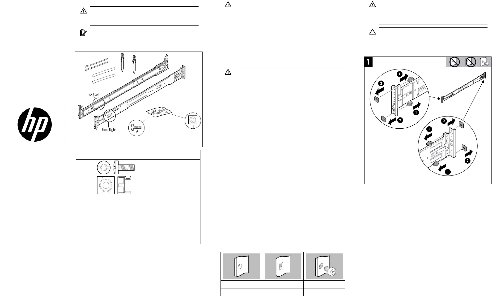
Hardware kit contents
WARNING: To reduce the risk of personal injury or
damage to the equipment, at least two people are
required to lift the server during installation or removal.
IMPORTANT: When installing the rack rails, be sure they
are oriented Front Left and Front Right, as indicated on the
rails.
Item Hardware (Scale: 1:1) Quantity/Tool
A
4/ Slotted T-25
B
4
Y
Not
shown
User provided You must provide the
following:
• Screws to secure the
slide mounting bracket
assemblies in a
threaded-hole rack
• Cage nuts for a
round-hole rack
In addition to the supplied items, you might need:
• Screws that fit a threaded-hole rack
• The appropriate screwdriver for the screws
• Kit 371482-B21 for integrated shipping in a round-hole rack
• An optional installation tool (695539-001). This tool is available
for assistance in installing the server into the rack. Refer to the tool
part number when contacting your local service representative.
Rack warnings
WARNING: To reduce the risk of personal injury or
damage to the equipment, be sure that:
• The leveling jacks are extended to the floor.
• The full weight of the rack rests on the leveling jacks.
• The stabilizing feet are attached to the rack if it is a
single-rack installation.
• The racks are coupled together in multiple-rack
installations.
• Only one component is extended at a time. A rack may
become unstable if more than one component is
extended for any reason.
WARNING: If you are going to use a lift, be sure to use a
lift that can handle the load of the component.
Anti-tip stabilizer
The anti-tip stabilizers provide stability and support when equipment is
installed, removed or accessed within the rack. Stabilizer kits are
available in both 600-mm and 800-mm versions. HP also recommends
using the side feet, provided with these kits, to stabilize stand-alone
racks from the other side. If you are stabilizing racks that are secured
together with baying kits, the side feet are optional on either end of the
row.
HP recommends that stabilizer option kits be used when one or more of
the following situations occur:
• The standard 600-mm (23.62-in) or 800-mm (31.50-in) front foot
is required with deployments of stand-alone racks.
• Side feet, which are included in the stabilizer kits, are
recommended to be installed as well.
Rack rows with four or more bayed racks, without a single
rack-mountable component exceeding 99.79 kg (220 lb), do not need
a stabilizer kit installed.
Overview
This rack hardware kit supports a variety of products in round-, square-,
or threaded-hole racks. Use the legend to identify installation steps
appropriate to the type of rack.
Rack identification legend
Round-hole racks Square-hole racks Threaded-hole racks
No tools required No tools required —
Installing the rail kit into a rack
WARNING: To avoid risk of personal injury or damage to
the equipment, do not stack anything on top of
rail-mounted equipment or use it as a work surface when
extended from the rack.
CAUTION: Always plan the rack installation so that the
heaviest item is on the bottom of the rack. Install the
heaviest item first, and continue to populate the rack from
the bottom to the top.
© Copyright 2013 Hewlett-Packard Development Company, L.P.
The information contained herein is subject to change without notice. The only
warranties for HP products and services are set forth in the express warranty
statements accompanying such products and services. Nothing herein should
be construed as constituting an additional warranty. HP shall not be liable for
technical or editorial errors or omissions contained herein.
Part Number: 726957-002
June 2013
Edition: 2
*726957-002*
726957-002