
HP h1000 G6 LFF SAS Cable Kit Installation Instructions

HP h1000 G6 LFF SAS
Cable Kit
Installation Instructions
For HP ProLiant DL170h G6
Servers
Legal notices
© Copyright 2009 Hewlett-Packard Development Company, L.P.
The information contained herein is subject to change without notice. The only
warranties for HP products and services are set forth in the express warranty
statements accompanying such products and services. Nothing herein should
be construed as constituting an additional warranty. HP shall not be liable for
technical or editorial errors or omissions contained herein.
Overview
This document contains instructions for installing the Mini SAS to
SATA cable into HP ProLiant DL170h G6 servers. This cable supports
connectivity to SAS or SATA drives from an HP Smart Array
Controller. The Mini SAS to SATA Cable is used for connecting an
HP Smart Array Controller to a 3.5" Large Form Factor (LFF) Hard
Disk Drive (HDD) cage backplane.
NOTE: For more information on preparing the server for
installation, refer to the
HP ProLiant DL100 Series Server
User Guide
included in the Easy Set-up CD.
Kit Contents
• Mini SAS to SATA cable
• Installation Instructions
Important Safety Information
Refer to the Important Safety Information document included with the
server.
WARNING: Electrostatic discharge (ESD) can damage
electronic components. Be sure you are properly
grounded (earthed) before beginning any installation
procedure.
Installation Guidelines
This installation is to be performed by qualified individuals who are
knowledgeable of the procedures, precautions, and hazards
associated with equipment containing hazardous electrical circuits.
Installing the Mini SAS to SATA Cable
1. Turn off the server and all the peripherals connected to it.
2. Unplug all external cables and AC power cords. If necessary,
label each one to expedite reassembly.
3. Disconnect telecommunication cables to avoid exposure to
shock hazard from ringing voltages.
4. Remove the unit from rack and place on a flat surface.
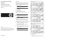
5. Connect the Mini SAS cable between the PCIe card and the
connectors on the HDD backplane. (Figure 1 or 2, depending
on the system category.)
NOTE: Your ProLiant server may be different from what
is shown in the illustrations below.
Figure 1 Install the Mini SAS to SATA cable into a 2-Node system
with 8 HDD backplane
Figure 2 Install the Mini SAS to SATA cable into the bottom Nodes in
a
4-Node system with 8 HDD backplane. Cables 3 and 4 are not
used in this configuration.
Figure 3 Install the Mini SAS to SATA cable into the top Nodes in a
4-Node system with 8 HDD backplane. Cables 3 and 4 are not used
in this configuration.
6. Reinstall the top cover.
7. Reinstall unit into rack.
8. Connect all external cables and the AC power cord to the
system.
Part number: 571803-001
J
uly 2009 (First edition)
9. Press the power button on the front panel to turn on the server.