
HP ProLiant DL170h G6 Graphics Bracket/Cable Kit Installation Instructions

HP ProLiant DL170h G6
Graphics Card
Bracket/Cable Kit
Installation Instructions
Legal notices
© Copyright 2009 Hewlett-Packard Development Company, L.P.
The information contained herein is subject to change without notice. The
only warranties for HP products and services are set forth in the express
warranty statements accompanying such products and services. Nothing
herein should be construed as constituting an additional warranty. HP shall
not be liable for technical or editorial errors or omissions contained herein.
Overview
This document contains instructions for installing graphics card
support bracket and the power cable into HP ProLiant DL170h G6
servers.
NOTE: For more information on preparing the server for
installation, refer to the
HP ProLiant DL100 Series Server
User Guide
included in the Easy Set-up CD.
Kit Contents
• Graphics card support bracket
• Power cable
• Installation instructions
Important Safety Information
Refer to the Important Safety Information document included with the
server.
WARNING: Electrostatic discharge (ESD) can damage
electronic components. Be sure you are properly
grounded (earthed) before beginning any installation
procedure.
Installation Guidelines
This installation is to be performed by qualified individuals who are
knowledgeable of the procedures, precautions, and hazards
associated with equipment containing hazardous electrical circuits.
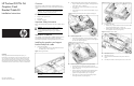
Installing the graphics card support
bracket and power cable
1. Remove the PCI Holder.
o Press the hooks and remove the PCI holder from the Riser
Air Baffle.
()
step 1 and 2 in Figure 1
Figure 1
Removing PCI Holder
NOTE: Please retain the PCI Holder for future use with
other cards.
2. Install the bottom piece of the graphics card support bracket.
o Align the bottom piece of the graphics card support bracket
to the chassis. (step 1 in Figure 2)
o Fasten the screw to secure the bracket to the chassis. (step
2 in Figure 2)
o Open the latch at the rear panel and remove blank. (step 3
in Figure 2)
Figure 2 Installing the bottom piece of the graphics card support
bracket
3. Install the graphics card.
o Align and put the graphics card into the chassis, making
sure it is secured by the slot on the air duct and the edge of
the riser card. (step 4 in Figure 3)
Figure 3 Installing the graphics card
4. Install the top piece of the graphics card support bracket.
o Close the latch at the rear panel. (step 5 in Figure 4)
o Fasten the screws to secure the graphics card to the chassis.
(step 6 in Figure 4)
o Align the top piece of the graphics card support bracket to
the screw holes and spools on the bottom piece of the
graphics card support bracket. (step 7 in Figure 4)
o Fasten the screw to secure the top piece of the graphics
card support bracket. (step 8 in Figure 4)
Figure 4 Installing the top piece of the graphics card support bracket
5. Install the power cable.
o Install the 12 pin power cable connector to the power cable
on the power backplane. (step 1 in Figure 5)
o Install the 8 pin power cable to the 8 pin power connector
on the graphics card. (step 2 in Figure 5)
Figure 5 Installing the power cable
6. Reinstall the top cover.
7. Reinstall unit into rack.
8. Connect all external cables and the AC power cord to the
system.
9. Press the power button on the front panel to turn on the server.
Part number 538638-002
September 2009 (second edition)