HP ProLiant DL560 Gen8 Server User Guide Abstract This document is for the person who installs, administers, and troubleshoots servers and storage systems. HP assumes you are qualified in the servicing of computer equipment and trained in recognizing hazards in products with hazardous energy levels.
© Copyright 2012, 2014 Hewlett-Packard Development Company, L.P. The information contained herein is subject to change without notice. The only warranties for HP products and services are set forth in the express warranty statements accompanying such products and services. Nothing herein should be construed as constituting an additional warranty. HP shall not be liable for technical or editorial errors or omissions contained herein. Microsoft® and Windows® are U.S.
Contents Component identification ............................................................................................................... 6 Front panel components ................................................................................................................................ 6 Front panel LEDs and buttons ......................................................................................................................... 6 Systems Insight Display LEDs ............................
Hardware options installation....................................................................................................... 34 Introduction ............................................................................................................................................... 34 Processor option......................................................................................................................................... 34 Memory options ............................................
Option ROM Configuration for Arrays................................................................................................ 76 ROMPaq utility................................................................................................................................. 77 Automatic Server Recovery ................................................................................................................ 77 USB support ............................................................................
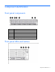
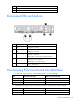
Component identification Front panel components Item Description 1 Video connector 2 Serial pull tab 3 USB connector 4 Fan module 5 Hot-plug hard drive 6 Systems Insight Display Front panel LEDs and buttons Component identification 6
Item Description Status 1 NIC status LED Solid green = Link to network Flashing green (1 Hz/cycle per sec) = Network active Off = No network activity 2 Health LED Solid green = Normal Flashing amber = System degraded Flashing red (1 Hz/cycle per sec) = System critical Fast-flashing red (4 Hz/cycles per sec) = Power fault* 3 Power On/Standby button and system power LED Solid green = System on Flashing green (1 Hz/cycle per sec) = Performing power on sequence Solid amber = System in standby Off = N
Item Description Status 2 NIC link/activity Off = No link to network. If the power is off, view the rear panel RJ-45 LEDs for status ("Rear panel LEDs and buttons" on page 10). Flashing green = Network link and activity Solid green = Network link 3 AMP status Off = AMP modes disabled Solid green = AMP mode enabled Solid amber = Failover Flashing amber = Invalid configuration 4 Power cap Off = System is in standby, or no cap is set.
Systems Insight Display Health LED LED and color System power LED Status • • Power supply (amber) Amber Green that power supply is in standby. Power supply fault System board fault One or more of the following conditions may exist: • • • • Redundant power supply is installed and only one power supply is functional. AC power cord is not plugged into redundant power supply.
9 iLO connector 10 Serial connector 11 FlexibleLOM ports (Shown: 4x1Gb/Optional: 2x10Gb); port 1 on right side Rear panel LEDs and buttons Item Description Status 1 Power supply 1 LED Off = System is off or power supply has failed. Solid green = Normal 2 Power supply 2 LED Off = System is off or power supply has failed.
Slot PCIe 3-slot riser cage* PCIe 2-slot x16 riser cage 6 - HL/FH PCIe2 or PCIe3** x8 (8,4,2,1) — *Depending on the server model, the server might ship with one or two riser cages installed. **These slots can run 8 GT/s signaling rate in either PCIe2 or PCIe3 mode, depending on the capability of the installed processor. †PCIe slot 3 is connected to the southbridge and runs at the Gen2 signaling rate. Notes: "Primary" denotes the riser cage is installed in the primary riser connector.
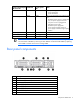
Item Description 4 Drive cage power connector 2 5 Processor 3 DIMM slots (1-6) 6 Systems Insight Display connector 7 Sideband signal connector 8 Processor 4 DIMM slots (7-12) 9 Processor 4 socket 10 Discovery services connector 11 Drive cage power connector 1 12 Front video connector 13 Processor 4 DIMM slots (1-6) 14 Processor 2 DIMM slots (1-6) 15 Power supply backplane connector 16 USB connector 1 17 System battery 18 MicroSD card slot 19 Internal USB connector 20 Secon
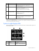
Position Default Function S6 Off Off = No function On = ROM reads system configuration as invalid. S7 — Reserved S8 — Reserved S9 — Reserved S10 — Reserved S11 — Reserved S12 — Reserved To access the redundant ROM, set S1, S5, and S6 to on. When the system maintenance switch position 6 is set to the On position, the system is prepared to erase all system configuration settings from both CMOS and NVRAM. CAUTION: Clearing CMOS and/or NVRAM deletes configuration information.
DIMM slot locations DIMM slots are numbered sequentially (1 through 12) for each processor. The supported AMP modes use the letter assignments for population guidelines.
Item LED Status Definition 1 Locate Solid blue The drive is being identified by a host application. Flashing blue The drive carrier firmware is being updated or requires an update. Rotating green Drive activity Off No drive activity Solid white Do not remove the drive. Removing the drive causes one or more of the logical drives to fail. Off Removing the drive does not cause a logical drive to fail. Solid green The drive is a member of one or more logical drives.
FBWC module LEDs (P222, P420, P421) The FBWC module has three single-color LEDs (one amber and two green). The LEDs are duplicated on the reverse side of the cache module to facilitate status viewing. 1 - Amber 2 - Green 3 - Green Interpretation Off Off Off The cache module is not powered. Off Flashing 0.5 Hz Flashing 0.5 Hz The cache microcontroller is executing from within its boot loader and receiving new flash code from the host controller.
CAUTION: To avoid damage to server components, all fan modules must be installed in fan bays for any processor configuration. For all processor configurations, the HP ProLiant DL560 Gen8 Server requires six fan modules for redundancy. A fan failure causes a loss of cooling redundancy. A second fan failure or a missing fan module causes an orderly shutdown of the server. The server supports variable fan speeds.
Operations Power up the server To power up the server, press the Power On/Standby button. Power down the server Before powering down the server for any upgrade or maintenance procedures, perform a backup of critical server data and programs. IMPORTANT: When the server is in standby mode, auxiliary power is still being provided to the system. To power down the server, use one of the following methods: • Press and release the Power On/Standby button.
2. Extend the server from the rack. 3. After performing the installation or maintenance procedure, slide the server back into the rack, and then press the server firmly into the rack to secure it in place. WARNING: To reduce the risk of personal injury, be careful when pressing the server rail-release latches and sliding the server into the rack. The sliding rails could pinch your fingers. Access the Systems Insight Display To access the HP Systems Insight Display: 1. Press and release the panel.
2. After the display fully ejects, rotate the display sideways to view the LEDs. Remove the access panel WARNING: To reduce the risk of personal injury from hot surfaces, allow the drives and the internal system components to cool before touching them. WARNING: To reduce the risk of personal injury, electric shock, or damage to the equipment, remove the power cord to remove power from the server. The front panel Power On/Standby button does not completely shut off system power.
3. Use a T-15 Torx screwdriver to tighten the security screw on the hood latch. Access the product rear panel Opening the cable management arm To access the server rear panel: 1. Release the cable management arm. 2. Open the cable management arm. Note that the cable management arm can be right-mounted or left-mounted.
WARNING: To reduce the risk of personal injury, electric shock, or damage to the equipment, remove the power cord to remove power from the server. The front panel Power On/Standby button does not completely shut off system power. Portions of the power supply and some internal circuitry remain active until AC power is removed. CAUTION: To prevent damage to the server or expansion boards, power down the server and remove all AC power cords before removing or installing the PCI riser cage. 1.
5. Install the PCIe riser cage. 6. Install the access panel (on page 20). 7. Install the server into the rack ("Installing the server into the rack" on page 30). 8. Connect each power cord to the server. 9. Connect each power cord to the power source. 10. Power up the server (on page 18). Remove the air baffle WARNING: To reduce the risk of personal injury, electric shock, or damage to the equipment, remove the power cord to remove power from the server.
CAUTION: Do not detach the cable that connects the battery pack to the cache module. Detaching the cable causes any unsaved data in the cache module to be lost. IMPORTANT: It is necessary to remove the PCI riser cage only if there is a full-length expansion board installed. 6. Remove the air baffle. Install the air baffle WARNING: To reduce the risk of personal injury, electric shock, or damage to the equipment, remove the power cord to remove power from the server.
5. Install the air baffle. 6. Install the access panel (on page 20). 7. Install the server into the rack ("Installing the server into the rack" on page 30). 8. Connect each power cord to the server. 9. Connect each power cord to the power source. 10. Power up the server (on page 18).
Setup Optional installation services Delivered by experienced, certified engineers, HP Care Pack services help you keep your servers up and running with support packages tailored specifically for HP ProLiant systems. HP Care Packs let you integrate both hardware and software support into a single package. A number of service level options are available to meet your needs.
• Leave a minimum clearance of 63.5 cm (25 in) in front of the rack. • Leave a minimum clearance of 76.2 cm (30 in) behind the rack. • Leave a minimum clearance of 121.9 cm (48 in) from the back of the rack to the back of another rack or row of racks. HP servers draw in cool air through the front door and expel warm air through the rear door.
Power requirements Installation of this equipment must comply with local and regional electrical regulations governing the installation of information technology equipment by licensed electricians. This equipment is designed to operate in installations covered by NFPA 70, 1999 Edition (National Electric Code) and NFPA-75, 1992 (code for Protection of Electronic Computer/Data Processing Equipment).
WARNING: When installing a DC power supply, the ground wire must be connected before the positive or negative leads. WARNING: Remove power from the power supply before performing any installation steps or maintenance on the power supply. CAUTION: The server equipment connects the earthed conductor of the DC supply circuit to the earthing conductor at the equipment. For more information, see the HP 750W Common Slot -48V DC Input Hot-Plug Power Supply Kit Installation Instructions.
WARNING: To reduce the risk of personal injury or equipment damage when unloading a rack: • At least two people are needed to safely unload the rack from the pallet. An empty 42U rack can weigh as much as 115 kg (253 lb), can stand more than 2.1 m (7 ft) tall, and might become unstable when being moved on its casters. • Never stand in front of the rack when it is rolling down the ramp from the pallet. Always handle the rack from both sides.
4. Install the power cord anchors. 5. Secure the cables to the cable management arm. IMPORTANT: When using cable management arm components, be sure to leave enough slack in each of the cables to prevent damage to the cables when the server is extended from the rack. 6. Connect the power cord to the AC power source. WARNING: To reduce the risk of electric shock or damage to the equipment: • Do not disable the power cord grounding plug. The grounding plug is an important safety feature.
Installing the operating system This ProLiant server ships with Intelligent Provisioning installed. Everything needed to manage and install the system software and firmware is preloaded on the server. To operate properly, the server must have a supported operating system. For the latest information on operating system support, see the HP website (http://www.hp.com/go/supportos).
Registering the server To experience quicker service and more efficient support, register the product at the HP Product Registration website (http://register.hp.com).
Hardware options installation Introduction If more than one option is being installed, read the installation instructions for all the hardware options and identify similar steps to streamline the installation process. WARNING: To reduce the risk of personal injury from hot surfaces, allow the drives and the internal system components to cool before touching them. CAUTION: To prevent damage to electrical components, properly ground the server before beginning any installation procedure.
7. Open the heatsink retaining bracket, and then remove the blank, if present. CAUTION: The pins on the processor socket are very fragile. Any damage to them may require replacing the system board. 8. Open each of the processor locking levers in the order indicated, and then open the processor retaining bracket.
9. Remove the clear processor socket cover. Retain the processor socket cover for future use. 10. Install the processor. Verify that the processor is fully seated in the processor retaining bracket by visually inspecting the processor installation guides on either side of the processor. THE PINS ON THE SYSTEM BOARD ARE VERY FRAGILE AND EASILY DAMAGED. CAUTION: THE PINS ON THE SYSTEM BOARD ARE VERY FRAGILE AND EASILY DAMAGED.
CAUTION: Do not press down on the processor. Pressing down on the processor may cause damage to the processor socket and the system board. Press only in the area indicated on the processor retaining bracket. 12. Press and hold the processor retaining bracket in place, and then close each processor locking lever. Press only in the area indicated on the processor retaining bracket. 13. Remove the thermal interface protective cover from the heatsink.
14. Install the heatsink. 15. Install the air baffle (on page 24). 16. Install any full-length expansion boards, if previously removed. 17. Install the access panel (on page 20). 18. Install the server into the rack ("Installing the server into the rack" on page 30). 19. Connect each power cord to the server. 20. Connect each power cord to the power source. Memory options IMPORTANT: This server does not support mixing LRDIMMs, RDIMMs, or UDIMMs.
• Single- and dual-rank PC3-10600 (DDR-1333) RDIMMs operating at up to 1333 MT/s at 1.35V • Single- and dual-rank PC3-12800 (DDR-1600) RDIMMs operating at up to 1600 MT/s at 1.5V • Single- and dual-rank PC3-12800 (DDR-1600) RDIMMs operating at up to 1600 MT/s at 1.35V • Single- and dual-rank PC3-14900 (DDR3-1866) RDIMMs, operating at up to 1866 MT/s at 1.5V • Quad-rank PC3L-10600 (DDR3-1333) LRDIMMs, operating at up to 1333 MT/s at 1.
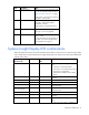
DIMM type DIMM rank LRDIMM LRDIMM Quad-rank (32 GB) Quad-rank (32 GB) 1 DIMM per channel 2 DIMMs per channel 3 DIMMs per channel 1333 1333 1066 1866 1066 13332 4 4 Supported with the BIOS RBSU setting IVB memory 3 RDIMM supports 1.35V 3DPC at 1066. Third-party memory supports 1.5V 3DPC at 1066 MT/s. 4 LRDIMM enables 3 DIMMs per channel. HP SmartMemory supports up to 3DPC at 1066 MT/s at 1.35V. Third-party memory supports 1.5V only.
Single-, dual-, and quad-rank DIMMs To understand and configure memory protection modes properly, an understanding of single-, dual-, and quad-rank DIMMs is helpful. Some DIMM configuration requirements are based on these classifications. A single-rank DIMM has one set of memory chips that is accessed while writing to or reading from the memory. A dual-rank DIMM is similar to having two single-rank DIMMs on the same module. A quad-rank DIMM is, effectively, two dual-rank DIMMs on the same module.
Item Description Definition 4 Voltage rating L = Low voltage (1.35V) U = Ultra low voltage (1.25V) Blank or omitted = Standard 5 Memory speed 12800 = 1600-MT/s 10600 = 1333-MT/s 8500 = 1066-MT/s 6 DIMM type R = RDIMM (registered) E = UDIMM (unbuffered with ECC) L = LRDIMM (load reduced) For the latest supported memory information, see the QuickSpecs on the HP website (http://www.hp.com/go/productbulletin).
Advanced ECC provides additional protection over Standard ECC because it is possible to correct certain memory errors that would otherwise be uncorrected and result in a server failure. Using HP Advanced Memory Error Detection technology, the server provides notification when a DIMM is degrading and has a higher probability of uncorrectable memory error. Online Spare memory configuration Online spare memory provides protection against degraded DIMMs by reducing the likelihood of uncorrected memory errors.
Online spare population For Online Spare memory mode configurations, observe the following guidelines: • Observe the general DIMM slot population guidelines (on page 43). • Each channel must have a valid online spare configuration. • Each channel can have a different valid online spare configuration. • Each populated channel must have a spare rank: o A single dual-rank DIMM is not a valid configuration. o LRDIMMs are treated as dual-rank DIMMs.
a. Disconnect each power cord from the power source. b. Disconnect each power cord from the server. 3. Extend the server from the rack (on page 18). 4. Remove the access panel (on page 20). 5. Remove the air baffle (on page 23). 6. Open the DIMM slot latches.. 7. Install the DIMM. 8. Install the air baffle (on page 24). 9. Install the access panel (on page 20). 10. Install the server into the rack ("Installing the server into the rack" on page 30). 11. Connect each power cord to the server.
CAUTION: For proper cooling, do not operate the server without the access panel, baffles, expansion slot covers, or blanks installed. If the server supports hot-plug components, minimize the amount of time the access panel is open. 1. Determine the status of the drive from the hot-plug SAS drive LED combinations ("Hot-plug drive LED definitions" on page 14). 2. Back up all server data on the drive. 3. Remove the drive.
2. Prepare the drive. 3. Install the drive. 4. Determine the status of the drive from the drive LED definitions ("Hot-plug drive LED definitions" on page 14). Controller options The server ships with an embedded Smart Array P420i controller. For more information about the storage controller and its features, select the relevant controller user documentation on the HP website (http://www.hp.com/go/smartstorage/docs).
CAUTION: To prevent a server malfunction or damage to the equipment, do not add or remove the battery pack while an array capacity expansion, RAID level migration, or stripe size migration is in progress. CAUTION: After the server is powered down, wait 15 seconds and then check the amber LED before unplugging the cable from the cache module. If the amber LED blinks after 15 seconds, do not remove the cable from the cache module. The cache module is backing up data, and data is lost if the cable is detached.
7. Install the cache module. 8. Connect the capacitor pack cable to the connector on the top of the cache module. 9. Install the access panel (on page 20). 10. Install the server into the rack ("Installing the server into the rack" on page 30). 11. Connect each power cord to the server. 12. Connect each power cord to the power source. 13. Power up the server (on page 18).
To install the component: 1. Back up all data. 2. Close all applications. WARNING: To reduce the risk of personal injury, electric shock, or damage to the equipment, remove the power cord to remove power from the server. The front panel Power On/Standby button does not completely shut off system power. Portions of the power supply and some internal circuitry remain active until AC power is removed.
10. o Single capacitor pack holder o Double capacitor pack holder Install the FBWC capacitor pack holder into the server.
o Single capacitor pack holder o Double capacitor pack holder 11. Install the access panel (on page 20). 12. Install the server into the rack ("Installing the server into the rack" on page 30). 13. Connect each power cord to the server. 14. Connect each power cord to the power source. 15. Power up the server (on page 18). Redundant hot-plug power supply option CAUTION: All power supplies installed in the server must have the same output power capacity.
Label color Output Green 1,200W CAUTION: To prevent improper cooling and thermal damage, do not operate the server unless all bays are populated with either a component or a blank. To install the component: 1. Access the product rear panel (on page 21). 2. Remove the blank. WARNING: To reduce the risk of personal injury from hot surfaces, allow the power supply or power supply blank to cool before touching it. 3. Insert the power supply into the power supply bay until it clicks into place. 4.
FlexibleLOM option WARNING: To reduce the risk of personal injury, electric shock, or damage to the equipment, remove the power cord to remove power from the server. The front panel Power On/Standby button does not completely shut off system power. Portions of the power supply and some internal circuitry remain active until AC power is removed. To remove the existing FlexibleLOM: 1. Power down the server (on page 18). 2. Remove all power: a. Disconnect each power cord from the power source. b.
To install the optional FlexibleLOM: 1. Firmly seat the FlexibleLOM in the slot, and then tighten the thumbscrew. 2. Install the PCIe riser cage ("Install the primary PCIe riser cage" on page 22). 3. Install the access panel (on page 20). 4. Slide the server into the rack. 5. Connect the LAN segment cables. 6. Connect each power cord to the server. 7. Connect each power cord to the power source. 8. Power up the server (on page 18).
a. Disconnect each power cord from the power source. b. Disconnect each power cord from the server. 3. Extend the server from the rack (on page 18). 4. Remove the access panel (on page 20). 5. Disconnect any external cables that are connected to the expansion board. 6. Disconnect any internal cables that are connected to the expansion board. 7. Remove the PCIe riser cage ("Remove the primary PCIe riser cage" on page 21). 8. Remove the expansion slot blank.
7. Install the expansion board. 8. Connect any required internal or external cables to the expansion board. See the documentation that ships with the expansion board. 9. Install the PCIe riser cage ("Install the primary PCIe riser cage" on page 22). 10. Install the access panel (on page 20). 11. Install the server into the rack ("Installing the server into the rack" on page 30). 12. Connect each power cord to the server. 13. Connect each power cord to the power source. 14.
5. Remove the PCIe riser cage. 6. Remove the expansion slot cover. 7. Install the expansion board. 8. Connect any required internal or external cables to the expansion board. See the documentation that ships with the expansion board. 9. Install the PCIe riser cage ("Install the primary PCIe riser cage" on page 22). 10. Secure the full-length expansion board retainer to the full-length expansion board. 11. Install the access panel (on page 20). 12.
a. Disconnect each power cord from the power source. b. Disconnect each power cord from the server. 3. Extend the server from the rack (on page 18). 4. Remove the access panel (on page 20). 5. Remove the PCI riser blank. 6. Remove the blank from the optional secondary PCI riser cage.
7. Install an expansion board into the PCI riser cage. 8. Install the optional secondary PCI riser cage. 9. If not already installed, install the secondary processor ("Processor option" on page 34). 10. Install the access panel (on page 20). 11. Install the server into the rack ("Installing the server into the rack" on page 30). 12. Connect each power cord to the server. 13. Connect each power cord to the power source. 14. Power up the server (on page 18).
Install the 2U rack bezel into the chassis, and then lock the 2U rack bezel with the key. HP Trusted Platform Module option For more information about product features, specifications, options, configurations, and compatibility, see the product QuickSpecs on the HP Product Bulletin website (http://www.hp.com/go/productbulletin). Use these instructions to install and enable a TPM on a supported server. This procedure includes three sections: 1. Installing the Trusted Platform Module board. 2.
• When using BitLocker, always retain the recovery key/password. The recovery key/password is required to enter Recovery Mode after BitLocker detects a possible compromise of system integrity. • HP is not liable for blocked data access caused by improper TPM use. For operating instructions, see the encryption technology feature documentation provided by the operating system.
9. Install the TPM security rivet by pressing the rivet firmly into the system board. 10. Install the air baffle (on page 24). 11. Install the PCI riser cage ("Install the primary PCIe riser cage" on page 22). 12. Install the access panel (on page 20). 13. Install the server into the rack ("Installing the server into the rack" on page 30). 14. Connect each power cord to the server. 15. Connect each power cord to the power source. 16. Power up the server (on page 18).
6. Press the Esc key to exit the current menu, or press the F10 key to exit RBSU. 7. Reboot the server. 8. Enable the TPM in the OS. For OS-specific instructions, see the OS documentation. CAUTION: When a TPM is installed and enabled on the server, data access is locked if you fail to follow the proper procedures for updating the system or option firmware, replacing the system board, replacing a hard drive, or modifying OS application TPM settings.
Cabling SAS drive cabling Cabling 65
FBWC cabling • SFF FBWC cabling • PCIe option Depending on the server configuration, you may need to remove the primary PCIe riser cage (on page 21) before cabling to a PCIe expansion board.
CAUTION: To prevent damage to the server or expansion boards, power down the server and remove all AC power cords before removing or installing the PCI expansion cage. Connect the cable as indicated.
Software and configuration utilities Server mode The software and configuration utilities presented in this section operate in online mode, offline mode, or in both modes.
iLO enables and manages the Active Health System (on page 69) and also features Agentless Management. All key internal subsystems are monitored by iLO. SNMP alerts are sent directly by iLO regardless of the host operating system or even if no host operating system is installed. HP Insight Remote Support software (on page 72) is also available in HP iLO with no operating system software, drivers, or agents.
The data that is collected is managed according to the HP Data Privacy policy. For more information see the HP website (http://www.hp.com/go/privacy). The Active Health System log, in conjunction with the system monitoring provided by Agentless Management or SNMP Pass-thru, provides continuous monitoring of hardware and configuration changes, system status, and service alerts for various server components. The Agentless Management Service is available in the SPP, which is a disk image (.
see the Resources tab on the HP website (http://www.hp.com/go/ilo). For consolidated drive and firmware update packages, see the HP Systems and Server Software Management page on the HP website (http://www.hp.com/go/SmartUpdate).
HP Insight Remote Support software HP strongly recommends that you register your device for remote support to enable enhanced delivery of your HP Warranty, HP Care Pack Service, or HP contractual support agreement.
• For more information about installing HP Insight Remote Support and enabling HP Insight Online, see the HP Insight Remote Support and Insight Online Setup Guide for ProLiant Gen8 Servers and BladeSystem c-Class Enclosures. These documents are available on the HP website (http://www.hp.com/go/insightremotesupport/docs).
HP ROM-Based Setup Utility RBSU is a configuration utility embedded in HP ProLiant servers that performs a wide range of configuration activities that can include the following: • Configuring system devices and installed options • Enabling and disabling system features • Displaying system information • Selecting the primary boot controller • Configuring memory options • Language selection For more information on RBSU, see the HP ROM-Based Setup Utility User Guide on the HP RBSU Information Libr
Drives installed Drives used RAID level 1 1 RAID 0 2 2 RAID 1 3, 4, 5, or 6 3, 4, 5, or 6 RAID 5 More than 6 0 None To change any ORCA default settings and override the auto-configuration process, press the F8 key when prompted. For more information on RBSU, see the HP ROM-Based Setup Utility User Guide on the HP RBSU Information Library (http://www.hp.com/go/rbsu/docs). Boot options Near the end of the boot process, the boot options screen is displayed.
5. Press the Enter key to clear the warning. 6. Enter the serial number and press the Enter key. 7. Select Product ID. The following warning appears: Warning: The Product ID should ONLY be modified by qualified service personnel. This value should always match the Product ID located on the chassis. 8. Enter the product ID and press the Enter key. 9. Press the Esc key to close the menu. 10. Press the Esc key to exit RBSU. 11. Press the F10 key to confirm exiting RBSU.
For more information regarding the default configurations that ORCA uses, see the HP ROM-Based Setup Utility User Guide on the Documentation CD or the HP RBSU Information Library (http://www.hp.com/go/rbsu/docs). For more information about the storage controller and its features, select the relevant controller user documentation on the HP website (http://www.hp.com/go/smartstorage/docs). To configure arrays, see the HP Smart Storage Administrator User Guide on the HP website (http://www.hp.
Redundant ROM support The server enables you to upgrade or configure the ROM safely with redundant ROM support. The server has a single ROM that acts as two separate ROM images. In the standard implementation, one side of the ROM contains the current ROM program version, while the other side of the ROM contains a backup version. NOTE: The server ships with the same version programmed on each side of the ROM.
Version control The VCRM and VCA are web-enabled Insight Management Agents tools that HP SIM uses to schedule software update tasks to the entire enterprise. • VCRM manages the repository for SPP. Administrators can view the SPP contents or configure VCRM to automatically update the repository with internet downloads of the latest software and firmware from HP. • VCA compares installed software versions on the node with updates available in the VCRM managed repository.
Change control and proactive notification HP offers Change Control and Proactive Notification to notify customers 30 to 60 days in advance of upcoming hardware and software changes on HP commercial products. For more information, refer to the HP website (http://www.hp.com/go/pcn).
Troubleshooting Troubleshooting resources The HP ProLiant Gen8 Troubleshooting Guide, Volume I: Troubleshooting provides procedures for resolving common problems and comprehensive courses of action for fault isolation and identification, issue resolution, and software maintenance on ProLiant servers and server blades. To view the guide, select a language: • English (http://www.hp.com/support/ProLiant_TSG_v1_en) • French (http://www.hp.com/support/ProLiant_TSG_v1_fr) • Spanish (http://www.hp.
Battery replacement If the server no longer automatically displays the correct date and time, you may need to replace the battery that provides power to the real-time clock. Under normal use, battery life is 5 to 10 years. WARNING: The computer contains an internal lithium manganese dioxide, a vanadium pentoxide, or an alkaline battery pack. A risk of fire and burns exists if the battery pack is not properly handled. To reduce the risk of personal injury: • • • • Do not attempt to recharge the battery.
IMPORTANT: Replacing the system board battery resets the system ROM to its default configuration. After replacing the battery, reconfigure the system through RBSU. To replace the component, reverse the removal procedure. For more information about battery replacement or proper disposal, contact an authorized reseller or an authorized service provider.
Regulatory information Safety and regulatory compliance For safety, environmental, and regulatory information, see Safety and Compliance Information for Server, Storage, Power, Networking, and Rack Products, available at the HP website (http://www.hp.com/support/Safety-Compliance-EnterpriseProducts). Turkey RoHS material content declaration Ukraine RoHS material content declaration Warranty information HP ProLiant and X86 Servers and Options (http://www.hp.
Electrostatic discharge Preventing electrostatic discharge To prevent damaging the system, be aware of the precautions you need to follow when setting up the system or handling parts. A discharge of static electricity from a finger or other conductor may damage system boards or other static-sensitive devices. This type of damage may reduce the life expectancy of the device. To prevent electrostatic damage: • Avoid hand contact by transporting and storing products in static-safe containers.
Specifications Environmental specifications Specification Value Temperature range* Operating 10°C to 35°C (50°F to 95°F) Shipping -30°C to 50°C (-22°F to 122°F) Storage -30°C to 60°C (-22°F to 140°F) Maximum wet bulb temperature 28°C (82.4°F) Relative humidity (noncondensing)** Operating 10% to 90% Non-operating 5% to 95% * All temperature ratings shown are for sea level. An altitude derating of 1°C per 300 m (1.8°F per 1,000 ft) to 3048 m (10,000 ft) is applicable. No direct sunlight allowed.
Rated input current 9.1 A at 100 VAC 6.
Support and other resources Before you contact HP Be sure to have the following information available before you call HP: • Active Health System log (HP ProLiant Gen8 or later products) Download and have available an Active Health System log for 3 days before the failure was detected. For more information, see the HP iLO 4 User Guide or HP Intelligent Provisioning User Guide on the HP website (http://www.hp.com/go/ilo/docs).
providers or service partners) identifies that the repair can be accomplished by the use of a CSR part, HP will ship that part directly to you for replacement. There are two categories of CSR parts: • Mandatory—Parts for which customer self repair is mandatory. If you request HP to replace these parts, you will be charged for the travel and labor costs of this service. • Optional—Parts for which customer self repair is optional. These parts are also designed for customer self repair.
Pour plus d'informations sur le programme CSR de HP, contactez votre Mainteneur Agrée local. Pour plus d'informations sur ce programme en Amérique du Nord, consultez le site Web HP (http://www.hp.com/go/selfrepair). Riparazione da parte del cliente Per abbreviare i tempi di riparazione e garantire una maggiore flessibilità nella sostituzione di parti difettose, i prodotti HP sono realizzati con numerosi componenti che possono essere riparati direttamente dal cliente (CSR, Customer Self Repair).
HINWEIS: Einige Teile sind nicht für Customer Self Repair ausgelegt. Um den Garantieanspruch des Kunden zu erfüllen, muss das Teil von einem HP Servicepartner ersetzt werden. Im illustrierten Teilekatalog sind diese Teile mit „No“ bzw. „Nein“ gekennzeichnet. CSR-Teile werden abhängig von der Verfügbarkeit und vom Lieferziel am folgenden Geschäftstag geliefert. Für bestimmte Standorte ist eine Lieferung am selben Tag oder innerhalb von vier Stunden gegen einen Aufpreis verfügbar.
sustituciones que lleve a cabo el cliente, HP se hará cargo de todos los gastos de envío y devolución de componentes y escogerá la empresa de transporte que se utilice para dicho servicio. Para obtener más información acerca del programa de Reparaciones del propio cliente de HP, póngase en contacto con su proveedor de servicios local. Si está interesado en el programa para Norteamérica, visite la página web de HP siguiente (http://www.hp.com/go/selfrepair).
Opcional – Peças cujo reparo feito pelo cliente é opcional. Essas peças também são projetadas para o reparo feito pelo cliente. No entanto, se desejar que a HP as substitua, pode haver ou não a cobrança de taxa adicional, dependendo do tipo de serviço de garantia destinado ao produto. OBSERVAÇÃO: Algumas peças da HP não são projetadas para o reparo feito pelo cliente. A fim de cumprir a garantia do cliente, a HP exige que um técnico autorizado substitua a peça.
Support and other resources 94
Support and other resources 95
Acronyms and abbreviations ABEND abnormal end ACU Array Configuration Utility AMP Advanced Memory Protection ASR Automatic Server Recovery CSA Canadian Standards Association CSR Customer Self Repair DDDC Double Device Data Correction DDR double data rate FBWC flash-backed write cache IEC International Electrotechnical Commission iLO Integrated Lights-Out IML Integrated Management Log Acronyms and abbreviations 96
LFF large form factor NMI nonmaskable interrupt NVRAM nonvolatile memory ORCA Option ROM Configuration for Arrays PCIe Peripheral Component Interconnect Express POST Power-On Self Test RBSU ROM-Based Setup Utility RDIMM registered dual in-line memory module RDP Rapid Deployment Pack SAS serial attached SCSI SATA serial ATA SDDC Single Device Data Correction SELV separated extra low voltage SFF small form factor Acronyms and abbreviations 97
SIM Systems Insight Manager TMRA recommended ambient operating temperature TPM Trusted Platform Module UDIMM unregistered dual in-line memory module UID unit identification USB universal serial bus VCA Version Control Agent Acronyms and abbreviations 98
Documentation feedback HP is committed to providing documentation that meets your needs. To help us improve the documentation, send any errors, suggestions, or comments to Documentation Feedback (mailto:docsfeedback@hp.com). Include the document title and part number, version number, or the URL when submitting your feedback.
Index A AC power supply 86 access panel 20 Advanced ECC memory 42, 44, air baffle 23, 24 Array Configuration Utility (ACU) ASR (Automatic Server Recovery) authorized reseller 88 auto-configuration process 74 Automatic Server Recovery (ASR) B battery 82 bezel, front 60 BIOS upgrade 68, 77 boot options 75 BSMI notice 84 buttons 6 C cable management arm 21, 30 cables 65 cabling 65 Canadian notice 84 capacitor pack 48 Care Pack 26, 72, 79 Change Control 80 components 6 components, identification 6 configurati
H hard drive bays 6, 14 hard drive LEDs 14 hard drives, determining status of 14 hardware options installation 30, 34 health driver 77 help resources 88 hot-plug fans 16, 21 hot-plug SAS hard drive options 45 HP Insight Diagnostics 71 HP Insight Remote Support software 72, 79 HP Service Pack for ProLiant 68, 71, 73 HP Smart Update Manager overview 40, 68, 73 HP technical support 79, 88 I iLO (Integrated Lights-Out) 68, 69, 70 IML (Integrated Management Log) 68, 70 Insight Diagnostics 71, 78 installation se
registering the server 33 regulatory compliance notices 84 removing a hot-plug SAS hard drive 45 removing the access panel 20 retaining the recovery key/password 63 ROM redundancy 78 ROMPaq utility 68, 77, 78 Version Control 79 video connector 6 W warnings 29 website, HP 88 S safety considerations 29, 78, 84, 85 scripted installation 73 serial number 75 series number 84 server features and options 34 server setup 26, 78 shipping carton contents 30 space and airflow requirements 26 specifications 86 speci