HP ProLiant DL580 Generation 3 Server Maintenance and Service Guide May 2006 (Sixth Edition) Part Number 379041-006
© Copyright 2005, 2006 Hewlett-Packard Development Company, L.P. The information contained herein is subject to change without notice. The only warranties for HP products and services are set forth in the express warranty statements accompanying such products and services. Nothing herein should be construed as constituting an additional warranty. HP shall not be liable for technical or editorial errors or omissions contained herein. Microsoft, Windows, and Windows NT are U.S.
Contents Illustrated parts catalog ................................................................................................................. 6 Customer self repair................................................................................................................................... 6 Mechanical components............................................................................................................................. 6 System components ........................................
Advanced ECC memory ................................................................................................................. 51 Online spare memory .................................................................................................................... 52 Hot-plug mirrored memory .............................................................................................................. 53 Hot-plug RAID memory ...........................................................................
RILOE II cabling ...................................................................................................................................... 90 Hot-plug SCSI drive cabling ...................................................................................................................... 91 SCSI simplex mode........................................................................................................................ 92 SCSI duplex mode .................................................
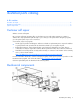
Illustrated parts catalog In this section Customer self repair ................................................................................................................................. 6 Mechanical components ........................................................................................................................... 6 System components ..................................................................................................................................
Original Modified assembly part assembly number part number Original spare part number Modified spare part number Customer self repair — 385642-001 — Yes 366450-002 — — — Yes b) Blank, CD/DVD/diskette 377569-001 — — — Yes 3 c) Blank, memory board 374278-001 — — — Yes 4 Bezel, ProLiant DL580 367600-001 G3 Server — 376481-001 — Yes 5 Cover, top, ProLiant DL580 G3 Server 367572-001 — 376480-001 — Yes 6 Blank, hard drive 302531-002 — 122759-001 — Yes Item Descripti
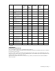
System components Item Description Original Modified Original assembly part assembly part spare part number number number Modified spare part number Customer self repair — System components — — — — — 1 Power supply, 910–1300 W 337867001‡ See requirement 337867-501 364360001‡ See requirement 406421-001 Yes 2 System cage — — — — 3 Fan 120 mm, hotplug 364517-001 — 374552-001 — Yes — Boards — — — — — 4 PCI-X Hot Plug switch 011077001‡ See requirement 011077-501 23098100
Original Modified Original assembly part assembly part spare part number number number Modified spare part number Customer self repair Item Description 8 Media board 012207(CD/DVD/diskette) 001‡ See requirement 012207-501 376477001‡ See requirement 416422-001 Yes 9 Power backplane, ProLiant DL580 G3 Server * 012110001‡ See requirement 012110-501 376476001‡ See requirement 411795-001 No 10 Processor module assembly, ProLiant DL580 G3 Server 012095001‡ See requirement 012095-501 376469001‡
Original Modified Original assembly part assembly part spare part number number number Modified spare part number Customer self repair Item Description — g) 72-GB SAS 375696-002 drive, 10,000 rpm * — 376597-001 — Yes — h) 36-GB SAS 375696-001 drive, 10,000 rpm * — 376596-001 — Yes — i) 60-GB SATA drive, 5,400 rpm * 390158-001 — 382264-001 — Yes — Memory — — — — — 17 DIMM, PC2-3200, — DDR2 — — — — — a) 512 MB * 345112051‡ See requirement 345112-851 359241001‡ See require
Item Description Original Modified Original assembly part assembly part spare part number number number Modified spare part number — g) Intel® 3.
Item Description Original Modified Original assembly part assembly part spare part number number number Modified spare part number 30 SAS array controller board * 012335-001 — 370855-001 — Yes 31 SAS array cache board (with battery) * 011773-002 — 309522-001 — Yes 32 SAS/SATA hard drive blank * 376383-001 — 392613-001 — Yes — Miscellaneous — — — — 33 Battery, 3V, Lithium * 166899-001 — 153009-001 — Yes 34 Power cord, AC line, C14-C19 * 287485-002 — 391097-001 — Yes 35
Removal and replacement procedures In this section Required tools........................................................................................................................................ 13 Safety considerations.............................................................................................................................. 14 Preparation procedures...........................................................................................................................
• Flathead screwdriver • Diagnostics Utility Safety considerations Before performing service procedures, review all the safety information. Preventing electrostatic discharge To prevent damaging the system, be aware of the precautions you need to follow when setting up the system or handling parts. A discharge of static electricity from a finger or other conductor may damage system boards or other static-sensitive devices. This type of damage may reduce the life expectancy of the device.
• Power down the server (on page 16). If you must remove a server from a rack or a non-hot-plug component from a server, power down the server. • Remove the server from the rack (on page 16). If the rack environment, cabling configuration, or the server location in the rack makes it difficult to service the unit, remove the server from the rack. • Remove the access panel ("Removing the access panel" on page 17). If you are servicing internal components, remove the access panel.
WARNING: To reduce the risk of personal injury or equipment damage, be sure that the rack is adequately stabilized before extending a component from the rack. WARNING: To reduce the risk of personal injury, be careful when pressing the server rail-release latches and sliding the server into the rack. The sliding rails could pinch your fingers. 3. After performing the installation or maintenance procedure, slide the server back into the rack by pressing the server rail-release latches.
Removing the access panel WARNING: To reduce the risk of personal injury from hot surfaces, allow the drives and the internal system components to cool before touching them. CAUTION: Do not operate the server for long periods with the access panel open or removed. Operating the server in this manner results in improper airflow and improper cooling that can lead to thermal damage.
8. Remove all power supplies ("Removing a redundant hot-plug power supply" on page 48). 9. Loosen the thumbscrews, and lift the system cage from the server. NOTE: The T-15 Torx screwdriver can be used to loosen the thumbscrews. The T-15 Torx screwdriver is shipped with the server and can be located on the rear panel ("Rear panel components" on page 73). Removing the front bezel 1. Power down the server (on page 16). 2.
6. Slide the bezel to the right, and detach the bezel from the server. To replace the component, reverse the removal procedure. Removing a media drive blank 1. Power down the server (on page 16). 2. Use the T-15 Torx screwdriver to eject the drive blank, and pull the drive blank out of the server. NOTE: The T-15 Torx screwdriver is shipped with the server and can be located on the rear panel ("Rear panel components" on page 73). To replace the component, reverse the removal procedure.
1. Power down the server (on page 16). 2. Use the T-15 Torx screwdriver to eject the drive, and pull the drive out of the server. NOTE: The T-15 Torx screwdriver is shipped with the server and can be located on the rear panel ("Rear panel components" on page 73). To replace the component, reverse the removal procedure. Removing the processor module NOTE: Refer the section "Processor module LEDs (on page 72)" for information on the current processor and PPM status. 1.
3. Release the latches to unlock the processor module. 4. Lower the processor module lever, and pull the module out of the server.
5. Release the latch, and open the cover to expose the processors. NOTE: To install a new processor module, remove all processors and PPMs from the processor module. Reinstall the processors and PPMs into the replacement processor module. To replace the component, reverse the removal procedure. Removing a processor CAUTION: To prevent thermal instability and damage to the server, do not separate the processor from the heatsink. The processor, heatsink, and retaining clip make up a single assembly.
3. Unlock the processor retaining bracket. 4. Open the processor retaining bracket, and open the processor locking lever. CAUTION: Failure to completely open the processor locking lever prevents the processor from seating during installation, leading to hardware damage. 5. Remove the processor.
6. Install the replacement processor assembly, if applicable. IMPORTANT: Determine the correct processor orientation by observing the guide pins on the base of the processor retaining bracket and the three corresponding guide slots on the processor assembly. 7. Insert the processor assembly into the processor socket, and close the locking lever. CAUTION: To prevent possible server malfunction or damage to the equipment, be sure to completely close the processor locking lever.
8. Close and lock the processor retaining bracket. 9. Close the cover, and replace the processor module. Removing a PPM The server PPMs provide the proper power to each processor. Each PPM must be installed in the correct slot for the processor. IMPORTANT: Processor socket 1 and PPM slot 1 must be populated at all times or the server does not function properly. IMPORTANT: Always install a PPM when you install a processor. The system fails to boot if the PPM is missing. To remove a PPM: 1.
3. Remove the PPM. IMPORTANT: Always install a PPM when you install a processor. The system fails to boot if the corresponding PPM is missing. To replace the component, reverse the removal procedure. Removing a PCI latch 1. Power down the server (on page 16). 2. Extend or remove the server from the rack ("Remove the server from the rack" on page 16). 3. Remove the access panel ("Removing the access panel" on page 17).
7. Remove the PCI latch by pushing up on the clear plastic piece of the PCI latch that extends below the chassis under the latch. To replace the component, reverse the removal procedure. Removing a PCI retaining clip 1. Power down the server (on page 16). 2. Extend or remove the server from the rack ("Remove the server from the rack" on page 16). 3. Remove the access panel ("Removing the access panel" on page 17).
To replace the component, reverse the removal procedure. Removing the PCI-X Hot Plug basket 1. Power down the server (on page 16). 2. Extend or remove the server from the rack ("Remove the server from the rack" on page 16). 3. Remove the access panel ("Removing the access panel" on page 17). CAUTION: To prevent improper cooling and thermal damage, do not operate the server unless all expansion slots have either an expansion slot cover or an expansion board installed. 4.
7. Remove the expansion board. To replace the component, reverse the removal procedure. Removing the PCI-X Hot Plug mezzanine option 1. Power down the server (on page 16). 2. Extend or remove the server from the rack ("Remove the server from the rack" on page 16). 3. Remove the access panel ("Removing the access panel" on page 17). 4. Remove the expansion boards from slots 1 and 2. 5. Remove the expansion boards from slots 3 and 4, if installed, to gain access to the mezzanine board. 6.
CAUTION: To prevent improper cooling and thermal damage, do not operate the server unless all expansion slots have either an expansion slot cover or an expansion board installed. To replace the component, reverse the removal procedure. Removing the PCI Express mezzanine option 1. Power down the server (on page 16). 2. Extend or remove the server from the rack ("Remove the server from the rack" on page 16). 3. Remove the access panel ("Removing the access panel" on page 17). 4.
2. Power down the failed server ("Power down the server" on page 16). If any data is trapped in the cache module, the amber LED on the module ("BBWC LEDs" on page 87) blinks every 15 seconds. CAUTION: Do not detach the cable that connects the battery pack to the cache module. Detaching the cable causes any unsaved data in the cache module to be lost. 3. Transfer the hard drives from the failed server to the recovery server station. 4.
IMPORTANT: The battery pack might have a low charge when installed. In this case, a POST error message is displayed when the server is powered up, indicating that the battery pack is temporarily disabled. No action is necessary on your part. The internal circuitry automatically recharges the batteries and enables the battery pack. This process might take up to four hours. During this time, the cache module functions properly, but without the performance advantage of the battery pack.
IMPORTANT: HP recommends troubleshooting the system using port 85 codes before replacing the system board. Refer to "Troubleshooting the system using port 85 codes (on page 64)" for a list of codes and troubleshooting procedures. 1. Power down the server (on page 16). 2. Remove all media drives ("Removing a media drive" on page 19) and media drive blanks ("Removing a media drive blank" on page 19). 3.
16. Using the lever, lift the system board slightly, and slide the system board out through the back of the server. IMPORTANT: If replacing the system board or clearing NVRAM, you must re-enter the server serial number through RBSU ("Re-entering the server serial number and product ID" on page 34). To replace the component, reverse the removal procedure. Re-entering the server serial number and product ID After you replace the system board, you must re-enter the server serial number and the product ID.
10. Press the F10 key to confirm exiting RBSU. The server will automatically reboot. Removing the system battery If the server no longer automatically displays the correct date and time, you might need to replace the battery that provides power to the real-time clock. Under normal use, battery life is five to 10 years. WARNING: The computer contains an internal lithium manganese dioxide, a vanadium pentoxide, or an alkaline battery pack.
4. Locate the battery. 5. Remove the battery.
To replace the component, reverse the removal procedure. Run RBSU to configure the server after replacing the battery. Refer to the HP ROM-Based Setup Utility User Guide on the Documentation CD for more detailed information. Removing the media board 1. Power down the server (on page 16). 2. Extend the server from the rack, if applicable ("Extending the server from the rack" on page 15). 3. Remove the access panel ("Removing the access panel" on page 17). 4.
8. Record the position of the SCSI simplex/duplex switch. 9. Lift the levers, and pull the SCSI backplane out of the server.
IMPORTANT: Be sure to set the SCSI simplex/duplex switch to the appropriate setting when replacing the SCSI backplane. To replace the component, reverse the removal procedure. Removing the power backplane 1. Power down the server (on page 16). 2. Remove all power supplies ("Removing a redundant hot-plug power supply" on page 48) and power supply blanks ("Removing a power supply blank" on page 48).
6. Open the latch, and lift the memory backplane from the server. To replace the component, reverse the removal procedure. Removing a hard drive blank CAUTION: To prevent improper cooling and thermal damage, do not operate the server unless all bays are populated with either a component or a blank. Remove the hard drive blank by squeezing the release buttons, and pulling the blank from the server. To replace the component, reverse the removal procedure.
CAUTION: To prevent improper cooling and thermal damage, do not operate the server unless all bays are populated with either a component or a blank. 1. Determine the status of the hard drive from the hot-plug hard drive LEDs ("Hot-plug SCSI hard drive LEDs" on page 82, "SATA or SAS hard drive LEDs" on page 84). 2. Back up all server data on the hard drive to be removed. 3. Remove the hard drive. To replace the component, reverse the removal procedure.
3. Remove the hard drive. Removing the SAS-SATA hard drive cage 1. Power down the server (on page 16). 2. Remove the access panel ("Removing the access panel" on page 17). 3. Remove all hard drives ("Removing a hot-plug SAS hard drive" on page 41) and hard drive blanks ("Removing a hard drive blank" on page 40). 4. Remove the screws securing the SAS hard drive cage. 5. Slowly pull the SAS hard drive cage out of the server until there is enough room to reach behind the SAS hard drive cage. 6.
7. Disconnect and remove the power and SAS cables, if applicable. To replace the SAS-SATA hard drive cage, perform the following procedures: CAUTION: The power transfer board is only installed in the HP ProLiant DL585 Server. Installing the power transfer board in the HP ProLiant DL580 Generation 3 Server might damage the board and server components. NOTE: You must provide a SAS controller before proceeding with the SAS hard drive cage installation. 1. Power down the server (on page 16). 2.
7. Route the SAS cables through the opening near the SCSI backplane and over the center wall. 8. Connect the cables to the connectors on the back of the SAS hard drive cage. NOTE: Port 1 supports hard drives 1 through 4. Port 2 supports hard drives 5 through 8. If you are using a single channel SAS controller, connect the cable to port 1.
9. Install the SAS hard drive cage, pulling the slack in the SAS cables over the center wall. 10. Connect the SAS cables to the controller. 11. Secure the SAS hard drive cage with the screws provided in the option kit. 12. Install the hot-plug hard drives or hard drive blanks into the SAS hard drive cage.
CAUTION: To prevent improper cooling and thermal damage, do not operate the server unless all bays are populated with either a component or a blank. The installation is complete. Removing the SAS-SATA backplane 1. Power down the server (on page 16). 2. Remove the access panel ("Removing the access panel" on page 17). 3. Remove all hard drives ("Removing a hot-plug SAS hard drive" on page 41) and hard drive blanks ("Removing a hard drive blank" on page 40). 4.
7. Remove the SAS backplane from the rear of the cage. To replace the component, reverse the removal procedure. Removing a PCI-X Hot Plug expansion board 1. Extend or remove the server from the rack ("Remove the server from the rack" on page 16). 2. Remove the access panel ("Removing the access panel" on page 17). 3. Press the PCI-X Hot Plug button to remove power from the slot. When the green power LED on the slot stops flashing, power has been removed from the slot. 4.
Removing a power supply blank NOTE: If you remove or replace the primary hot-plug power supply, use the T-15 Torx screwdriver provided with the server to remove the shipping screw. It is located just under the port-colored plastic handle of the power supply unit. 1. Remove the power supply blank. To replace the component, reverse the removal procedure. Removing a redundant hot-plug power supply WARNING: To reduce the risk of electric shock, do not disassemble the power supply or attempt to repair it.
3. Remove the hot-plug power supply from the server. CAUTION: To prevent improper cooling and thermal damage, do not operate the server unless all bays are populated with either a component or a blank. To replace the component, reverse the removal procedure. Replacing hot-plug fans The server supports redundant hot-plug fans ("Fan locations" on page 85) to provide proper airflow to the server if a primary fan fails.
4. Install the replacement fan. 5. Repeat to replace additional fans as needed. 6. Observe the LED on each installed fan to be sure it is illuminated green ("Hot-plug fan LEDs" on page 87). 7. Observe the internal system health LED on the front panel to be sure it is illuminated green ("Front panel LEDs and buttons" on page 69). NOTE: If the front panel internal system health LED is not green after you install hot-plug fans, reseat the hotplug fan or refer to the troubleshooting section.
• DIMMs must be installed in pairs. • DIMM pairs within a memory bank must contain DIMMs with the same part number. • Always populate the DIMMs in sequential order per bank: Bank A and then Bank B. • Always populate the memory boards in sequential order: Board 1, Board 2, Board 3, and Board 4. Any deviation from this requirement results in the server defaulting to Advanced ECC ("Advanced ECC memory" on page 51) on the next reboot.
ECC can correct single-bit memory errors, Advanced ECC can correct single-bit memory errors and multibit memory errors if all failed bits are on the same DRAM device on the DIMM. The following guidelines apply to Advanced ECC memory: • All general memory requirements apply. • Advanced ECC mode is supported with one to four memory boards. • Board insertions do not convert the AMP mode while the server is running.
• Each memory board includes its own online spare bank. All boards will operate in online spare memory mode independently. Each board can failover to its online spare bank independent of the other memory boards. Some boards can be in degraded online spare mode while others are still in operational online spare memory mode. • The minimum valid online spare configuration for a memory board requires at least one bank of dual-rank DIMMs or two banks of single-rank DIMMs.
size. For example, memory boards 1 and 2 could each contain 2 GB of physical memory per board with board 1 containing two 1-GB DIMMs and board 2 containing four 512-MB DIMMs. • The amount of memory between mirrored pairs can be different in quad-board Hot-Plug Mirrored Memory mode. For example, memory pair 1 (boards 1 and 2) can contain 2 GB each while memory pair 2 (boards 3 and 4) contain 4 GB each. • In quad-board hot-plug mirrored memory, the two pairs of memory boards operate independently.
Configuring the memory Configuring the memory system of the server requires configuring both hardware and software. To configure the memory: 1. Install the correct amount of memory for the desired AMP mode. For a list of AMP options, refer to "Memory options ("Memory overview" on page 50)." For more information, refer to "General memory configuration requirements (on page 50)." 2. Test the DIMMs for all AMP modes, except Advanced ECC, before configuring the AMP mode in RBSU.
5. Press the Escape key twice to go back to the main RBSU menu. 6. Press the F10 key, when prompted, to exit RBSU. The server reboots and tests all memory in the system. IMPORTANT: To reconfigure the memory mode after initial setup, you must reboot the system, enter RBSU, and select an AMP mode. Memory boards and DIMMs Memory board and DIMM removal and replacement procedures can be either hot-replace or non-hotplug, depending on how the server is configured.
Removing a memory board blank To remove the memory board blank, squeeze the levers and pull the blank out of the server. Removing a memory board (non-hot-plug) 1. Power down the server (on page 16). 2. Unlock the locking switch, and open the release latch. 3. Use the ejector lever to pull the memory board out of the server.
4. Open the memory board. 5. Replace the DIMM ("Removing DIMMs" on page 59). IMPORTANT: Be sure to observe all DIMM installation requirements for the desired memory mode. 6. Close the memory board. IMPORTANT: Be sure that the locking switch is unlocked. The memory board will not seat in the server if the locking switch is locked. 7. Install the memory board. 8. Close the ejector lever, and lock the locking switch. 9. Power up the server. 10.
CAUTION: Only memory boards with a green Removable LED can be removed. Do not attempt to remove any memory board with the Removable LED off. CAUTION: To prevent system failure, do not remove the memory board from the server until the board status LED stops flashing. 2. Unlock the locking switch, and open the release latch. 3. Use the ejector lever to pull the memory board out of the server.
Diagnostic tools In this section SmartStart software ................................................................................................................................ 60 SmartStart Scripting Toolkit...................................................................................................................... 60 HP Instant Support Enterprise Edition ........................................................................................................
ProLiant BL, ML, and DL servers. The toolkit includes a modular set of utilities and important documentation that describes how to apply these new tools to build an automated server deployment process. Using SmartStart technology, the Scripting Toolkit provides a flexible way to create standard server configuration scripts. These scripts are used to automate many of the manual steps in the server configuration process.
For more information on RBSU, refer to the HP ROM-Based Setup Utility User Guide on the Documentation CD or the HP website (http://www.hp.com/servers/smartstart). ROMPaq utility Flash ROM enables you to upgrade the firmware (BIOS) with system or option ROMPaq utilities. To upgrade the BIOS, insert a ROMPaq diskette into the diskette drive and boot the system. The ROMPaq utility checks the system and provides a choice (if more than one exists) of available ROM revisions.
Integrated Lights-Out technology The iLO subsystem is a standard component of selected ProLiant servers that provides server health and remote server manageability. The iLO subsystem includes an intelligent microprocessor, secure memory, and a dedicated network interface. This design makes iLO independent of the host server and its operating system. The iLO subsystem provides remote access to any authorized network client, sends alerts, and provides other server management functions.
For more information or to download the utility, refer to the HP website (http://www.hp.com/servers/diags). USB support HP provides both standard USB support and legacy USB support. Standard support is provided by the operating system through the appropriate USB device drivers. HP provides support for USB devices before the operating system loads through legacy USB support, which is enabled by default in the system ROM. HP hardware supports USB version 1.1 or 2.0, depending on the version of the hardware.
1. Bring the server to base configuration by removing all components that are not required by the server to complete POST. This process can include removing all: • Expansion boards ("Removing a non-hot-plug expansion board" on page 28, "Removing a PCI-X Hot Plug expansion board" on page 47) • Processors ("Removing a processor" on page 22), except the processor installed in socket 1 IMPORTANT: Processor socket 1 and PPM slot 1 must be populated at all times or the server does not function properly.
3. Install the expansion boards one at a time, rebooting between each installation to isolate the failed expansion board. 4. Replace the failed expansion board, if applicable. 5. Replace the PCI riser board, if applicable. 6. Replace the system board. IMPORTANT: If replacing the system board or clearing NVRAM, you must re-enter the server serial number through RBSU ("Re-entering the server serial number and product ID" on page 34).
• Expansion boards ("Removing a non-hot-plug expansion board" on page 28, "Removing a PCI-X Hot Plug expansion board" on page 47) • Processors ("Removing a processor" on page 22), except the processor installed in socket 1 IMPORTANT: Processor socket 1 and PPM slot 1 must be populated at all times or the server does not function properly.
Server component identification In this section Front panel components .......................................................................................................................... 68 Front panel LEDs and buttons ................................................................................................................... 69 Memory board components and LEDs....................................................................................................... 70 Processor module LEDs.......
Item Description 2 USB port 3 Optional multibay drive or blank 4 DVD drive 5 Processor module 6 Hard drive bay Front panel LEDs and buttons Item Description Status 1 UID switch and LED Blue = Activated Flashing blue = Server being managed remotely Off = Deactivated 2 Internal system health LED Green = Normal (system on) Flashing amber = System health is degraded Flashing red = System health is critical Off = Normal (system off) 3 External system health LED Green = Normal (system on)
Item Description Status 6 Power on/Standby button and LED Amber = System has AC power and is in standby mode Green = System has AC power and is turned on Off = System has no AC power Memory board components and LEDs Error indicators remain illuminated when the system is powered off so that the status of the LEDs can still be seen. This behavior matches the behavior of all the other error indicators in the server.
Item Description Status 5 DIMM LEDs (1–4) Off = Normal or DIMM not installed Amber = Uncorrectable error detected or correctable error threshold reached Flashing amber = DIMM configuration error 6 Spare Off = Board not online or board not configured for Online Spare Memory mode Amber = Correctable error threshold reached; server is in degraded Online Spare Memory mode Flashing amber = Memory configuration error* Green = Online Spare Memory mode 7 Mirrored Off = Board not online or board not confi
Processor module LEDs PPM LED (1) Processor LED (2) External health LED Description Off Off Off One of the following conditions exist: • No AC power present • Normal Off Amber Flashing amber Pre-failure error threshold exceeded; LEDs will clear after the next reboot Off Amber Flashing red One or more of the following conditions exist: • The processor was replaced and the LEDs will clear after the next reboot • Processor failed Off Flashing amber Flashing red Processor configuration
Rear panel components Item Description Item Description 1 PCI-X non-hot-plug slot 7, 64-bit/100MHz 11 NIC port 2 2 PCI-X non-hot-plug slot 6, 64-bit/100MHz 12 NIC port 1 3 PCI-X non-hot-plug slot 5, 64-bit/133MHz 13 Serial port 4 PCI-X non-hot-plug slot 4, 64-bit/133MHz 14 USB ports 5 PCI-X non-hot-plug slot 3, 64-bit/133MHz 15 Video port 6 Optional PCI-X Hot Plug or optional PCI 16 Express non-hot-plug expansion slot 2 Keyboard port 7 Optional PCI-X Hot Plug or optional PCI 17
Rear panel LEDs and buttons Item Description LED color Status 1 NIC 1 Activity LED Green On or flashing = Network activity Off = No network activity 2 NIC 1 Link LED Green On = Linked to network Off = Not linked to network 3 NIC 2 Activity LED Green On or flashing = Network activity Off = No network activity 4 NIC 2 Link LED Green On = Linked to network Off = Not linked to network 5 iLO NIC Activity LED Green On or flashing = Network activity Off = No network activity 6 iLO NIC Lin
Power supply LEDs Fail LED 1 (amber) Power LED 2 (green) Description Off Off No AC power to any power supply Flashing Off Power supply failure (over current) On Off No AC power to this power supply Off Flashing • AC power present • Standby mode Off On Normal Server component identification 75
System board components Item Description Item Description 1 Fan 1 12 PCI-X, non-hot-plug slot 7, 64bit/100-MHz 2 Fan 2 13 BBWC battery pack 3 Fan 3 14 Remote management connector 4 Fan 4 15 BBWC cache module socket 5 System maintenance switch 16 Fan 6 6 System battery 17 Fan 5 Server component identification 76
Item Description Item Description 7 Connectors for one of the following: 18 Boot device selector switch (default = FLP TOP) • PCI-X Hot Plug mezzanine option • PCI Express x4 mezzanine option • PCI Express x8 mezzanine option 8 PCI-X non-hot-plug slot 3, 64- 19 bit/133-MHz SCSI port A 9 PCI-X, non-hot-plug slot 4, 64- 20 bit/133-MHz SCSI simplex/duplex switch (default = duplex) 10 PCI-X, non-hot-plug slot 5, 64- 21 bit/133-MHz Port 84/85 code switch 11 PCI-X, non-hot-plug slot 6, 64-
When the boot device selector switch is set to FLP TOP, the optical drive in the bottom bay is designated as the primary optical drive. The diskette drive in the top bay is bootable. The server cannot boot from a diskette drive in the bottom bay when the boot device selector switch is set to FLP TOP. When the boot device selector switch is set to FLP BOT, the optical drive in the top bay is designated as the primary optical drive. The diskette drive in the bottom bay is bootable.
NOTE: The system management driver must be installed for the internal health LED to provide pre-failure and warranty conditions. LED Description Fan X One or more of the following conditions exist: PCI X • A fan is missing or not properly installed. • A fan failed. One or more of the following conditions exist: • A PCI address parity error was detected on the numbered PCI slot. • A PCI data parity error was detected on the numbered PCI slot.
LED Description OVER TEMP The internal temperature has exceeded operating levels. NO BOOT A "no boot" condition was detected. P84 Switch set to display port 84 codes. P85 Switch set to display port 85 codes ("Troubleshooting the system using port 85 codes" on page 64). Setting the switch to view port 85 codes To change the display on the QuickFind diagnostic panel to view port 84 and 85 codes ("Troubleshooting the system using port 85 codes" on page 64): 1.
The SCSI IDs for both simplex mode and duplex mode are illustrated. Always populate hard drive bays starting with the lowest SCSI ID. NOTE: These SCSI ID designations apply regardless of the controller or the configuration used.
Hot-plug SCSI hard drive LEDs Item LED description Status 1 Activity status On = Drive activity Flashing = High activity on the drive or drive is being configured as part of an array. Off = No drive activity 2 On = Drive is part of an array and is currently working. Online status Flashing = Drive is actively online. Off = Drive is offline.
Activity LED (1) Online LED Fault LED (2) (3) Interpretation On Off Do not remove the drive. Off The drive is being accessed, but (1) it is not configured as part of an array; (2) it is a replacement drive and rebuild has not yet started; or (3) it is spinning up during the POST sequence. Flashing Flashing Flashing Do not remove the drive. Removing a drive may cause data loss in non-fault-tolerant configurations.
• If only one hard drive is used, install it in the bay with the lowest number. • Hard drives must be SFF types. • Drives must be the same capacity to provide the greatest storage space efficiency when drives are grouped together into the same drive array. NOTE: ACU does not support mixing SAS and SATA drives in the same logical volume.
Online/activity LED (green) Fault/UID LED (amber/blue) Interpretation On Off The drive is online, but it is not active currently. Flashing regularly Amber, flashing (1 Hz) regularly (1 Hz) Do not remove the drive. Removing a drive may terminate the current operation and cause data loss. The drive is part of an array that is undergoing capacity expansion or stripe migration, but a predictive failure alert has been received for this drive.
This fan configuration allows the server to continue operating in non-redundant mode if a single fan fails in either zone. If the system detects two fan failures in the same zone, the server shuts down to avoid thermal damage.
Hot-plug fan LEDs Status Green = Operating normally Amber = Failed Off = No power BBWC LEDs Server status LED 1 (amber) LED 2 (green) Battery module status Server is on and has normal run time Off On Fast charging Off Flashing The microcontroller is waiting for communication from the host controller. Off Off The battery is fully charged.
Server status Server is off and is in data retention mode LED 1 (amber) LED 2 (green) Battery module status On Off A short exists in the connection of one or more of the three button cells within the battery module. Flashing Off An opening exists in the circuit between the positive and negative terminals of the battery module. Off Off Normal Flashing every 15 seconds Off User data held in the write cache is being backed up.
Server cabling In this section Storage device cabling guidelines............................................................................................................ 89 PCI-X Hot Plug mezzanine cabling............................................................................................................ 89 BBWC cabling....................................................................................................................................... 90 RILOE II cabling ........................
CAUTION: When routing cables, always be sure that the cables are not in a position where they can be pinched or crimped. BBWC cabling CAUTION: When routing cables, always be sure that the cables are not in a position where they can be pinched or crimped. IMPORTANT: The BBWC cable is wound around the battery pack. Unwind the cable to the appropriate length before installing the battery pack assembly into the server. RILOE II cabling The 30-pin Remote Insight cable ships with the RILOE II cable kit.
CAUTION: When routing cables, always be sure that the cables are not in a position where they can be pinched or crimped. IMPORTANT: Install the RILOE II board into slot 7 for ease of cabling. Hot-plug SCSI drive cabling CAUTION: When routing cables, always be sure that the cables are not in a position where they can be pinched or crimped.
SCSI simplex mode In the PCI simplex cabling configuration, an optional PCI array controller controls up to four hard drives through one SCSI bus. SCSI duplex mode In the PCI duplex cabling configuration, an optional PCI array controller controls up to four hard drives through two SCSI buses. Each bus controls two hard drives. Hot-plug SAS hard drive cabling CAUTION: When routing cables, always be sure that the cables are not in a position where they can be pinched or crimped.
For ease of cabling, route the cables in the server before connecting the cables to the SAS hard drive cage. NOTE: Port 1 supports hard drives 1 through 4. Port 2 supports hard drives 5 through 8. If you are using a single channel SAS controller, connect the cable to port 1. USB cable assembly The USB cable connects the front panel USB connector to the SCSI backplane. To remove the component: 1. Power down the server (on page 16). 2.
7. Loosen the screw, and slide the USB cable connector up to remove the cable assembly from the server. To replace the component, reverse the removal procedure. Power switch cable assembly 1. Power down the server (on page 16). 2. Extend the server from the rack ("Extending the server from the rack" on page 15). 3. Remove the access panel ("Removing the access panel" on page 17). 4. Remove the front bezel ("Removing the front bezel" on page 18). 5. Disconnect all cables from the media board. 6.
9. Remove the power switch cable assembly. To replace the component, reverse the removal procedure.
Specifications In this section Server specifications ............................................................................................................................... 96 Environmental specifications .................................................................................................................... 96 Hot-plug power supply calculations ..........................................................................................................
Specification Value Relative humidity (noncondensing)** — Operating 10% to 90% Non-operating 5% to 95% * All temperature ratings shown are for sea level. An altitude derating of 1°C per 300 m (1.8°F per 1,000 ft) to 3048 m (10,000 ft) is applicable. No direct sunlight allowed. ** Storage maximum humidity of 95% is based on a maximum temperature of 45°C (113°F). Altitude maximum for storage corresponds to a pressure minimum of 70 KPa.
Acronyms and abbreviations ABEND abnormal end AMP Advanced Memory Protection ASR Automatic Server Recovery BBWC battery-backed write cache BP backplane CSA Canadian Standards Association DDR double data rate DIMM dual inline memory module ECC error checking and correcting IEC International Electrotechnical Commission iLO Integrated Lights-Out IML Integrated Management Log Acronyms and abbreviations 98
IPL initial program load IRQ interrupt request LED light-emitting diode MPS multi-processor specification NEMA National Electrical Manufacturers Association NFPA National Fire Protection Association NIC network interface controller NVRAM non-volatile memory ORCA Option ROM Configuration for Arrays PCI peripheral component interface PCI Express peripheral component interconnect express PCI-X peripheral component interconnect extended PCIe peripheral component interconnect express PDU power distr
POST Power-On Self Test PPM processor power module PSP ProLiant Support Pack PXE Preboot Execution Environment RBSU ROM-Based Setup Utility RILOE II Remote Insight Lights-Out Edition II SAS serial attached SCSI SATA serial ATA SCSI small computer system interface SDRAM synchronous dynamic RAM SIM Systems Insight Manager SPM system power module SSD support software diskette TMRA recommended ambient operating temperature Acronyms and abbreviations 100
UID unit identification USB universal serial bus VCA Version Control Agent VHDCI very high density cable interconnect Acronyms and abbreviations 101
Index A access panel 6, 17 ASR (Automatic Server Recovery) 63, 98 Automatic Server Recovery (ASR) 63, 98 Autorun menu 60 B batteries, replacing 35 battery 8, 35 battery pack LEDs 30, 31, 32, 87 battery-backed write cache 30, 31, 32, 90 battery-backed write cache battery pack 30, 31, 32, 90 battery-backed write cache cabling 30, 31, 32, 90 BIOS upgrade 62 boot device selector switch 77 buttons 68, 69, 94 C cabling 89, 92 cabling, power switch 94 cabling, SCSI hard drive 91 cabling, USB 93 CD-ROM drive 19 C
Integrated Management Log (IML) 62 internal components 76, 77, 78, 80, 85, 87 L LED, power button 69 LEDs 68, 69, 70, 72, 75, 82, 84, 87 LEDs, cache module 87 LEDs, hard drive 82, 84 LEDs, memory board 70 M management tools 60 mechanical components 6 media board 37 media drive 8, 19 media drive blank 6, 19 memory backplane 8, 39 memory boards 50, 56, 57, 70 memory overview 50 memory, Advanced ECC 51 memory, configuration requirements 50 memory, configuring 50, 55 memory, mirrored 53 memory, online spare 5
SATA cabling 92 SATA drives 83 scripted installation 60 SCSI backplane 37 SCSI hard drive cabling 91 SCSI hard drive cabling, duplex mode 92 SCSI hard drive cabling, SCSI mode 92 SCSI IDs 80 serial number 34 server asset text 34 server warnings and cautions 14 SmartStart autorun menu 60 SmartStart Scripting Toolkit 60 SmartStart, overview 60 specifications 96 specifications, environmental 96 static electricity 14 support packs 60 system battery 8, 35 system board 8, 32, 34, 75, 76 system cage 17 system comp