
ProLiant DL580 Generation 3 Server Maintenance and Service Guide
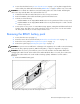
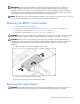
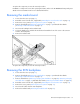
Table Of Contents
- HP ProLiant DL580 Generation 3 Server Maintenance and Service Guide
- Notice
- Contents
- Illustrated parts catalog
- Removal and replacement procedures
- Required tools
- Safety considerations
- Preparation procedures
- Removing the front bezel
- Removing a media drive blank
- Removing a media drive
- Removing the processor module
- Removing a processor
- Removing a PPM
- Removing a PCI latch
- Removing a PCI retaining clip
- Removing the PCI-X Hot Plug basket
- Removing a non-hot-plug expansion board
- Removing the PCI-X Hot Plug mezzanine option
- Removing the PCI Express mezzanine option
- Recovering data from the BBWC
- Removing the BBWC battery pack
- Removing the BBWC cache module
- Removing the system board
- Removing the system battery
- Removing the media board
- Removing the SCSI backplane
- Removing the power backplane
- Removing the memory backplane
- Removing a hard drive blank
- Removing a hot-plug SCSI hard drive
- Removing a hot-plug SAS hard drive
- Removing the SAS-SATA hard drive cage
- Removing the SAS-SATA backplane
- Removing a PCI-X Hot Plug expansion board
- Removing a power supply blank
- Removing a redundant hot-plug power supply
- Replacing hot-plug fans
- Memory overview
- Diagnostic tools
- SmartStart software
- SmartStart Scripting Toolkit
- HP Instant Support Enterprise Edition
- Option ROM Configuration for Arrays
- HP ROM-Based Setup Utility
- ROMPaq utility
- System Online ROM flash component utility
- Integrated Management Log
- Integrated Lights-Out technology
- Automatic Server Recovery
- HP Systems Insight Manager
- HP Insight Diagnostics
- USB support
- Troubleshooting the system using port 85 codes
- Server component identification
- Front panel components
- Front panel LEDs and buttons
- Memory board components and LEDs
- Processor module LEDs
- Rear panel components
- Rear panel LEDs and buttons
- Power supply LEDs
- System board components
- DIMM slot locations
- SCSI IDs
- Hot-plug SCSI hard drive LEDs
- Hot-plug SCSI hard drive LED combinations
- SATA or SAS IDs
- SATA or SAS hard drive LEDs
- SAS and SATA hard drive LED combinations
- Fan locations
- Hot-plug fan LEDs
- BBWC LEDs
- Server cabling
- Specifications
- Acronyms and abbreviations
- Index
Removal and replacement procedures 34
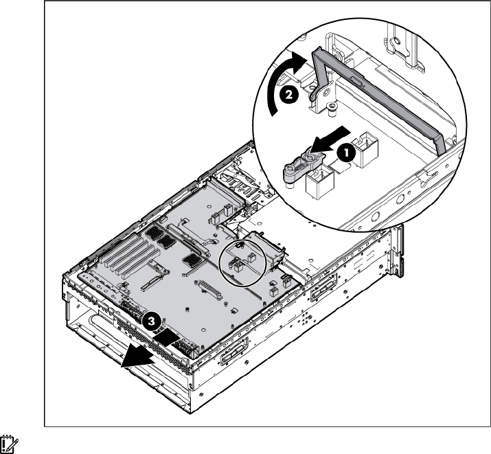
16.
Using the lever, lift the system board slightly, and slide the system board out through the back of the
server.
IMPORTANT: If replacing the system board or clearing NVRAM, you must re-enter the server serial number
through RBSU ("Re-entering the server serial number and product ID" on page 34).
To replace the component, reverse the removal procedure.
Re-entering the server serial number and product ID
After you replace the system board, you must re-enter the server serial number and the product ID.
1. During the server startup sequence, press the F9 key to access RBSU.
2. Select the Advanced Options menu.
3. Select Serial Number. The following warning is displayed:
Warning: The serial number should ONLY be modified by qualified service
personnel. This value should always match the serial number located on
the chassis.
4. Press the Enter key to clear the warning.
5. Enter the serial number.
6. Select Product ID. The following warning is displayed.
Warning: The Product ID should ONLY be modified by qualified service
personnel. This value should always match the Product ID located on the
chassis.
7. Enter the product ID and press the Enter key.
8. Press the Escape key to close the menu.
9. Press the Escape key to exit RBSU.