
ProLiant DL580 Generation 3 Server Maintenance and Service Guide
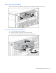
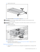
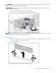
Table Of Contents
- HP ProLiant DL580 Generation 3 Server Maintenance and Service Guide
- Notice
- Contents
- Illustrated parts catalog
- Removal and replacement procedures
- Required tools
- Safety considerations
- Preparation procedures
- Removing the front bezel
- Removing a media drive blank
- Removing a media drive
- Removing the processor module
- Removing a processor
- Removing a PPM
- Removing a PCI latch
- Removing a PCI retaining clip
- Removing the PCI-X Hot Plug basket
- Removing a non-hot-plug expansion board
- Removing the PCI-X Hot Plug mezzanine option
- Removing the PCI Express mezzanine option
- Recovering data from the BBWC
- Removing the BBWC battery pack
- Removing the BBWC cache module
- Removing the system board
- Removing the system battery
- Removing the media board
- Removing the SCSI backplane
- Removing the power backplane
- Removing the memory backplane
- Removing a hard drive blank
- Removing a hot-plug SCSI hard drive
- Removing a hot-plug SAS hard drive
- Removing the SAS-SATA hard drive cage
- Removing the SAS-SATA backplane
- Removing a PCI-X Hot Plug expansion board
- Removing a power supply blank
- Removing a redundant hot-plug power supply
- Replacing hot-plug fans
- Memory overview
- Diagnostic tools
- SmartStart software
- SmartStart Scripting Toolkit
- HP Instant Support Enterprise Edition
- Option ROM Configuration for Arrays
- HP ROM-Based Setup Utility
- ROMPaq utility
- System Online ROM flash component utility
- Integrated Management Log
- Integrated Lights-Out technology
- Automatic Server Recovery
- HP Systems Insight Manager
- HP Insight Diagnostics
- USB support
- Troubleshooting the system using port 85 codes
- Server component identification
- Front panel components
- Front panel LEDs and buttons
- Memory board components and LEDs
- Processor module LEDs
- Rear panel components
- Rear panel LEDs and buttons
- Power supply LEDs
- System board components
- DIMM slot locations
- SCSI IDs
- Hot-plug SCSI hard drive LEDs
- Hot-plug SCSI hard drive LED combinations
- SATA or SAS IDs
- SATA or SAS hard drive LEDs
- SAS and SATA hard drive LED combinations
- Fan locations
- Hot-plug fan LEDs
- BBWC LEDs
- Server cabling
- Specifications
- Acronyms and abbreviations
- Index

Removal and replacement procedures 58
4.
Open the memory board.
5. Replace the DIMM ("Removing DIMMs" on page 59).
IMPORTANT: Be sure to observe all DIMM installation requirements for the desired memory mode.
6. Close the memory board.
IMPORTANT: Be sure that the locking switch is unlocked. The memory board will not seat in the server if
the locking switch is locked.
7. Install the memory board.
8. Close the ejector lever, and lock the locking switch.
9. Power up the server.
10. Reference the memory board LEDs ("Memory board components and LEDs" on page 70) to be sure
that the memory board is functioning properly.
Removing a memory board
1. Power down the server if the server is not configured for hot-plug RAID memory or hot-plug mirrored
memory.