
ProLiant DL580 Generation 3 Server Maintenance and Service Guide


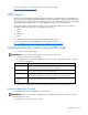
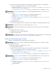
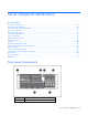
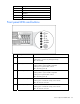
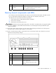
Table Of Contents
- HP ProLiant DL580 Generation 3 Server Maintenance and Service Guide
- Notice
- Contents
- Illustrated parts catalog
- Removal and replacement procedures
- Required tools
- Safety considerations
- Preparation procedures
- Removing the front bezel
- Removing a media drive blank
- Removing a media drive
- Removing the processor module
- Removing a processor
- Removing a PPM
- Removing a PCI latch
- Removing a PCI retaining clip
- Removing the PCI-X Hot Plug basket
- Removing a non-hot-plug expansion board
- Removing the PCI-X Hot Plug mezzanine option
- Removing the PCI Express mezzanine option
- Recovering data from the BBWC
- Removing the BBWC battery pack
- Removing the BBWC cache module
- Removing the system board
- Removing the system battery
- Removing the media board
- Removing the SCSI backplane
- Removing the power backplane
- Removing the memory backplane
- Removing a hard drive blank
- Removing a hot-plug SCSI hard drive
- Removing a hot-plug SAS hard drive
- Removing the SAS-SATA hard drive cage
- Removing the SAS-SATA backplane
- Removing a PCI-X Hot Plug expansion board
- Removing a power supply blank
- Removing a redundant hot-plug power supply
- Replacing hot-plug fans
- Memory overview
- Diagnostic tools
- SmartStart software
- SmartStart Scripting Toolkit
- HP Instant Support Enterprise Edition
- Option ROM Configuration for Arrays
- HP ROM-Based Setup Utility
- ROMPaq utility
- System Online ROM flash component utility
- Integrated Management Log
- Integrated Lights-Out technology
- Automatic Server Recovery
- HP Systems Insight Manager
- HP Insight Diagnostics
- USB support
- Troubleshooting the system using port 85 codes
- Server component identification
- Front panel components
- Front panel LEDs and buttons
- Memory board components and LEDs
- Processor module LEDs
- Rear panel components
- Rear panel LEDs and buttons
- Power supply LEDs
- System board components
- DIMM slot locations
- SCSI IDs
- Hot-plug SCSI hard drive LEDs
- Hot-plug SCSI hard drive LED combinations
- SATA or SAS IDs
- SATA or SAS hard drive LEDs
- SAS and SATA hard drive LED combinations
- Fan locations
- Hot-plug fan LEDs
- BBWC LEDs
- Server cabling
- Specifications
- Acronyms and abbreviations
- Index
Server component identification 70
Item Description Status
6
Power on/Standby button
and LED
Amber = System has AC power and is in standby mode
Green = System has AC power and is turned on
Off = System has no AC power
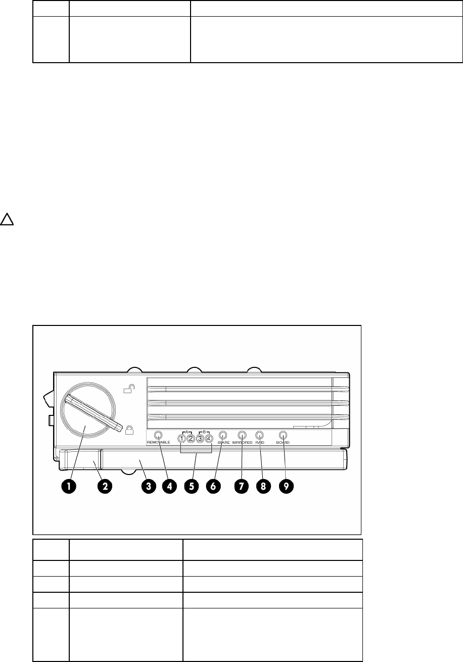
Memory board components and LEDs
Error indicators remain illuminated when the system is powered off so that the status of the LEDs can still
be seen. This behavior matches the behavior of all the other error indicators in the server.
The indicators are only cleared in the following situations:
• If the locking switch is locked after the board is reinstalled
• If the server is rebooted
• If the board is removed from the server
CAUTION: When the memory board locking switch is unlocked in a mode that does not support hot-add or
hot-replace capabilities, audio alarms and visual alerts occur. Removing the memory board at this point
causes server failure.
To end the audio alarms and visual alerts, move the memory board locking switch back to the locked position.
This action does not result in data corruption or server failure.
If removal of a single memory board is required and it is the only memory board, power down the server and
make the necessary memory changes.
Item Description Status
1 Locking switch N/A
2 Release latch N/A
3 Ejector lever N/A
4 Removable
Off = Do not remove memory board if
server is powered on
Green = Memory board can be safely
removed