
ProLiant DL580 Generation 3 Server Maintenance and Service Guide
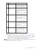
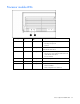
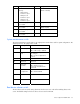
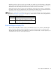
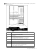
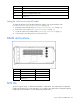
Table Of Contents
- HP ProLiant DL580 Generation 3 Server Maintenance and Service Guide
- Notice
- Contents
- Illustrated parts catalog
- Removal and replacement procedures
- Required tools
- Safety considerations
- Preparation procedures
- Removing the front bezel
- Removing a media drive blank
- Removing a media drive
- Removing the processor module
- Removing a processor
- Removing a PPM
- Removing a PCI latch
- Removing a PCI retaining clip
- Removing the PCI-X Hot Plug basket
- Removing a non-hot-plug expansion board
- Removing the PCI-X Hot Plug mezzanine option
- Removing the PCI Express mezzanine option
- Recovering data from the BBWC
- Removing the BBWC battery pack
- Removing the BBWC cache module
- Removing the system board
- Removing the system battery
- Removing the media board
- Removing the SCSI backplane
- Removing the power backplane
- Removing the memory backplane
- Removing a hard drive blank
- Removing a hot-plug SCSI hard drive
- Removing a hot-plug SAS hard drive
- Removing the SAS-SATA hard drive cage
- Removing the SAS-SATA backplane
- Removing a PCI-X Hot Plug expansion board
- Removing a power supply blank
- Removing a redundant hot-plug power supply
- Replacing hot-plug fans
- Memory overview
- Diagnostic tools
- SmartStart software
- SmartStart Scripting Toolkit
- HP Instant Support Enterprise Edition
- Option ROM Configuration for Arrays
- HP ROM-Based Setup Utility
- ROMPaq utility
- System Online ROM flash component utility
- Integrated Management Log
- Integrated Lights-Out technology
- Automatic Server Recovery
- HP Systems Insight Manager
- HP Insight Diagnostics
- USB support
- Troubleshooting the system using port 85 codes
- Server component identification
- Front panel components
- Front panel LEDs and buttons
- Memory board components and LEDs
- Processor module LEDs
- Rear panel components
- Rear panel LEDs and buttons
- Power supply LEDs
- System board components
- DIMM slot locations
- SCSI IDs
- Hot-plug SCSI hard drive LEDs
- Hot-plug SCSI hard drive LED combinations
- SATA or SAS IDs
- SATA or SAS hard drive LEDs
- SAS and SATA hard drive LED combinations
- Fan locations
- Hot-plug fan LEDs
- BBWC LEDs
- Server cabling
- Specifications
- Acronyms and abbreviations
- Index
Server component identification 78
When the boot device selector switch is set to FLP TOP, the optical drive in the bottom bay is designated
as the primary optical drive. The diskette drive in the top bay is bootable. The server cannot boot from a
diskette drive in the bottom bay when the boot device selector switch is set to FLP TOP.
When the boot device selector switch is set to FLP BOT, the optical drive in the top bay is designated as
the primary optical drive. The diskette drive in the bottom bay is bootable. The server cannot boot from a
diskette drive in the top bay when the boot device selector switch is set to FLP BOT.
NOTE: If two optical drives are installed in the server, the server will first attempt to boot from the primary
optical drive ("Boot device selector switch" on page 77). The boot device selector switch setting determines
which drive is the primary optical drive.
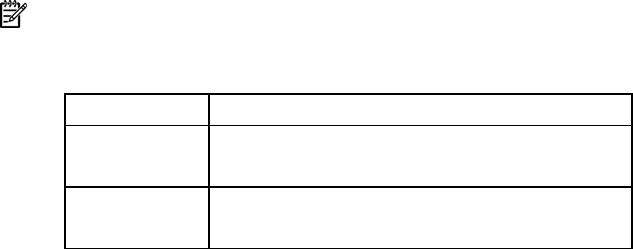
Switch setting Description
FLP TOP (default) Diskette drive in top bay is bootable
Primary optical drive in bottom bay is bootable
FLP BOT Primary optical drive in top bay is bootable
Diskette drive in bottom bay is bootable
QuickFind diagnostic display LEDs
The front panel health LEDs indicate only the current hardware status. In some situations, HP SIM might
report server status differently than the health LEDs because the software tracks more system attributes.
The amber QuickFind diagnostic display LEDs are located on the media board. In normal operations, all
of the LEDs are off unless one of the components fails.