HP ProLiant DL580 Generation 4 Server User Guide Part Number 407334-002 April 2007 (Second Edition)
© Copyright 2005, 2007 Hewlett-Packard Development Company, L.P. The information contained herein is subject to change without notice. The only warranties for HP products and services are set forth in the express warranty statements accompanying such products and services. Nothing herein should be construed as constituting an additional warranty. HP shall not be liable for technical or editorial errors or omissions contained herein. Microsoft, Windows, and Windows NT are U.S.
Contents Server component identification...................................................................................................... 7 Front panel components ............................................................................................................................. 7 Front panel LEDs and buttons ...................................................................................................................... 8 Memory board components and LEDs ................................
Introduction ............................................................................................................................................ 39 Processor options .................................................................................................................................... 39 Removing the processor module ...................................................................................................... 39 Installing a processor ..........................................
Re-entering the server serial number and product ID..................................................................................... 89 Management tools................................................................................................................................... 90 Automatic Server Recovery ............................................................................................................. 90 ROMPaq utility....................................................................
Unsupported PCI Card Detected Remove PCI Card from Slot ............................................................. 114 Unsupported Processor Configuration (Processor Required in Slot #1) ................................................ 114 WARNING - Mixed Feature Processors Were Detected .................................................................... 114 WARNING - Mixed Stepping Processors were detected. System cannot proceed................................. 114 WARNING - Resetting Corrupted CMOS ..
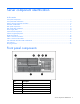
Server component identification In this section Front panel components ............................................................................................................................ 7 Front panel LEDs and buttons ..................................................................................................................... 8 Memory board components and LEDs......................................................................................................... 9 Processor module LEDs...
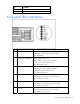
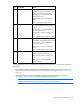
Item Description 6 Hard drive bay 7 Processor module Front panel LEDs and buttons Item Description Status 1 UID switch and LED Blue = Activated Flashing blue = Server being managed remotely Off = Deactivated 2 Internal system health LED Green = Normal (system on) Flashing amber = System health is degraded Flashing red = System health is critical Off = Normal (system off) 3 External system health LED Green = Normal (system on) Flashing amber = System health is degraded Flashing red = System
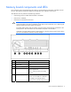
Memory board components and LEDs Error indicators remain illuminated when the system is powered off so that the status of the LEDs can still be seen. This behavior matches the behavior of all the other error indicators in the server.
Item Description Status 6 Spare Off = Board not online or board not configured for Online Spare Memory mode Amber = Correctable error threshold reached; server is in degraded Online Spare Memory mode Flashing amber = Memory configuration error* Green = Online Spare Memory mode 7 Mirrored Off = Board not online or board not configured for Hot-Plug Mirrored Memory mode Amber = Server is in degraded Hot-Plug Mirrored Memory mode Flashing amber = Memory configuration error* Green = Hot-Plug Mirrored Mem
Processor module LEDs PPM LED (1) Processor LED (2) External health LED Description Off Off Off One of the following conditions exist: • No AC power present • Normal Off Amber Flashing amber Pre-failure error threshold exceeded; LEDs will clear after the next reboot Off Amber Flashing red One or more of the following conditions exist: • The processor was replaced and the LEDs will clear after the next reboot • Processor failed Off Flashing amber Flashing red Processor configurati
Rear panel components Item Description Item 1 PCI Express non-hot-plug expansion slot 11 7 NIC connector 2 2 PCI Express non-hot-plug expansion slot 12 6 NIC connector 1 3 PCI Express non-hot-plug expansion slot 13 5 Serial connector 4 PCI Express non-hot-plug expansion slot 14 4 USB connectors 5 PCI-X non-hot-plug slot 3, 64-bit/133MHz Video connector 6 Optional PCI-X Hot Plug or optional PCI 16 Express non-hot-plug expansion slot 2 Keyboard connector 7 Optional PCI-X Hot Plug or opt
Rear panel LEDs and buttons Item Description LED color Status 1 NIC 1 Activity LED Green On or flashing = Network activity Off = No network activity 2 NIC 1 Link LED Green On = Linked to network Off = Not linked to network 3 NIC 2 Activity LED Green On or flashing = Network activity Off = No network activity 4 NIC 2 Link LED Green On = Linked to network Off = Not linked to network 5 iLO 2 NIC Activity LED Green On or flashing = Network activity Off = No network activity 6 iLO 2 NIC
Power supply LEDs Fail LED 1 (amber) Power LED 2 (green) Description Off Off No AC power to any power supply Flashing Off Power supply failure (over current) On Off No AC power to this power supply Off Flashing • AC power present • Standby mode Off On Normal Server component identification 14
System board components Item Description Item Description 1 Fan 1 10 PCI Express non-hot-plug expansion slot 4 2 Fan 2 11 PCI Express non-hot-plug expansion slot 5 3 Fan 3 12 PCI Express non-hot-plug expansion slot 6 4 Fan 4 13 PCI Express non-hot-plug expansion slot 7 5 System maintenance switch 14 Fan 6 6 System battery 15 Fan 5 Server component identification 15
Item Description Item Description 7 Connectors for one of the following: 16 Boot device selector switch (default = FLP TOP) • PCI-X Hot Plug mezzanine option • PCI Express x4 mezzanine option • PCI Express x8 mezzanine option 8 Battery packs and connectors 17 for BBWC (optional) Systems Insight Display 9 PCI-X non-hot-plug expansion — slot 3, 64-bit/133-MHz — System maintenance switch The system maintenance switch (SW1) is an eight-position switch that is used for system configuration.
When the boot device selector switch is set to FLP TOP, the optical drive in the bottom bay is designated as the primary optical drive. The diskette drive in the top bay is bootable. The server cannot boot from a diskette drive in the bottom bay when the boot device selector switch is set to FLP TOP. When the boot device selector switch is set to FLP BOT, the optical drive in the top bay is designated as the primary optical drive. The diskette drive in the bottom bay is bootable.
LED Description Fan X One or more of the following conditions exist: PCI X • A fan is missing or not properly installed. • A fan failed. One or more of the following conditions exist: • A PCI address parity error was detected on the numbered PCI slot. • A PCI data parity error was detected on the numbered PCI slot. MEDIA BP The media backplane is missing or not properly installed. MEM A memory board is not properly installed. MEM BP A memory backplane is missing or not properly installed.
LED Description P85 Switch set to display port 85 codes. see the HP ProLiant DL580 Generation 4 Maintenance and Service Guide on the Documentation CD for more information about troubleshooting using port 85 codes.
SATA or SAS drive numbers The server supports eight SAS or SATA hot-plug hard drives. See "SAS and SATA hard drive guidelines (on page 45)" for information about installing the hard drives.
Item LED description Status 2 Online/Activity status Green = Drive activity Flashing green = High activity on the drive or drive is being configured as part of an array Off = No drive activity SAS and SATA hard drive LED combinations Online/activity LED (green) Fault/UID LED (amber/blue) On, off, or flashing Alternating amber and The drive has failed, or a predictive failure alert has been blue received for this drive; it also has been selected by a management application.
• Zone 1 contains four fans (three, plus one redundant) to control the temperature in the processor module area. • Zone 2 contains two fans (one, plus one redundant) to control the temperature in the hard drive bay area. This fan configuration allows the server to continue operating in non-redundant mode if a single fan fails in either zone. If the system detects two fan failures in the same zone, the server shuts down to avoid thermal damage.
Hot-plug fan LEDs Status Green = Operating normally Amber = Failed Off = No power Server component identification 23
Server operations In this section Power up the server ................................................................................................................................ 24 Power down the server............................................................................................................................ 24 Extending the server from the rack............................................................................................................ 24 Removing the access panel.....
• Diskette drive • Hard drives To extend the server from the rack: 1. Release the two levers on the lower outside corners of the rack. 2. If the server is in a rack and in the shipping configuration, remove the two shipping screws directly behind the levers. 3. Extend the server on the rack rails until the server rail-release latches engage. NOTE: The release latches will lock into place when the rails are fully extended.
4. After performing the installation or maintenance procedure, slide the server back into the rack by pressing the server rail-release latches. Removing the access panel WARNING: To reduce the risk of personal injury from hot surfaces, allow the drives and the internal system components to cool before touching them. CAUTION: Do not operate the server for long periods with the access panel open or removed.
3. Lift up on the hood latch, and remove the access panel. 4. After installing hardware options, replace the access panel. Be sure that the panel is securely locked into place before powering up the server. Replacing hot-plug fans The server supports redundant hot-plug fans ("Fan locations" on page 21) to provide proper airflow to the server if a primary fan fails. WARNING: To prevent personal injury from hazardous energy: • Remove watches, rings, or other metal objects.
4. Install the replacement fan. 5. Repeat to replace additional fans as needed. 6. Observe the LED on each installed fan to be sure it is illuminated green ("Hot-plug fan LEDs" on page 23). 7. Observe the internal system health LED on the front panel to be sure it is illuminated green ("Front panel LEDs and buttons" on page 8). NOTE: If the front panel internal system health LED is not green after you install hot-plug fans, reseat the hot-plug fan or refer to the troubleshooting section.
Accessing the Systems Insight Display 1. Extend the server from the rack, if applicable ("Extending the server from the rack" on page 24). 2. Remove the access panel ("Removing the access panel" on page 26). IMPORTANT: When removing the access panel to view the Systems Insight Display LEDs (on page 17), leave the server powered on. The Systems Insight Display LEDs are cleared when the server is powered off.
3. Locate the Systems Insight Display. Battery If the server no longer automatically displays the correct date and time, you may need to replace the battery that provides power to the real-time clock. Under normal use, battery life is 5 to 10 years. WARNING: The computer contains an internal lithium manganese dioxide, a vanadium pentoxide, or an alkaline battery pack. A risk of fire and burns exists if the battery pack is not properly handled.
5. Remove the battery. To replace the component, reverse the removal procedure. For more information about battery replacement or proper disposal, contact an authorized reseller or an authorized service provider.
Server setup In this section Optional installation services ................................................................................................................... 32 Rack planning resources ......................................................................................................................... 33 Optimum environment............................................................................................................................. 33 Rack warnings and cautions ........
For more information on Care Packs, refer to the HP website (http://www.hp.com/hps/carepack/servers/cp_proliant.html). Rack planning resources The rack resource kit ships with all HP branded or Compaq branded 9000, 10000, and H9 series racks. For more information on the content of each resource, refer to the rack resource kit documentation. If you intend to deploy and configure multiple servers in a single rack, refer to the white paper on highdensity deployment at the HP website (http://www.hp.
CAUTION: If a third-party rack is used, observe the following additional requirements to ensure adequate airflow and to prevent damage to the equipment: • Front and rear doors—If the 42U rack includes closing front and rear doors, you must allow 5,350 sq cm (830 sq in) of holes evenly distributed from top to bottom to permit adequate airflow (equivalent to the required 64 percent open area for ventilation).
Electrical grounding requirements The server must be grounded properly for proper operation and safety. In the United States, you must install the equipment in accordance with NFPA 70, 1999 Edition (National Electric Code), Article 250, as well as any local and regional building codes. In Canada, you must install the equipment in accordance with Canadian Standards Association, CSA C22.1, Canadian Electrical Code.
WARNING: This server is very heavy. To reduce the risk of personal injury or damage to the equipment: • Observe local occupational health and safety requirements and guidelines for manual material handling. • Get help to lift and stabilize the product during installation or removal, especially when the product is not fastened to the rails. When the server weighs more than 22.5 kg (50 lb), at least two people must lift the server into the rack together.
Installing hardware options Install any hardware options before initializing the server. For options installation information, refer to the option documentation. For server-specific information, refer to "Hardware options installation (on page 39)." Installing the server into the rack Refer to the installation instructions that ship with the rack kit to install the server into the rack.
Registering the server To register the server, refer to the HP Registration website (http://register.hp.com).
Hardware options installation In this section Introduction ........................................................................................................................................... 39 Processor options ................................................................................................................................... 39 SAS and SATA hard drive guidelines .......................................................................................................
2. Release the latches to unlock the processor module. 3. Lower the processor module lever, and pull the module out of the server.
4. Release the latch, and open the cover to expose the processors. Installing a processor Processors must be installed in the following order: processor 1, processor 2, processor 4, and processor 3. Server PPMs provide the proper power to each processor. Each PPM must be installed in the slot adjacent to its processor. CAUTION: To prevent thermal instability and damage to the server, do not separate the processor from the heatsink. The processor, heatsink, and retaining clip make up a single assembly.
3. Unlock the processor retaining bracket. 4. Open the processor retaining bracket. 5. Open the processor locking lever. CAUTION: Failure to completely open the processor locking lever prevents the processor from seating during installation, leading to hardware damage.
6. If installed, remove the processor blank by lifting the processor blank from the processor socket. 7. Determine the correct processor orientation, and install the processor assembly into the processor socket. IMPORTANT: Determine the correct processor orientation by observing the guide pins on the base of the processor retaining bracket and the three corresponding guide slots on the processor assembly. 8. Insert the processor assembly into the processor socket, and close the locking lever.
9. Close and lock the processor retaining bracket. 10. Install the PPM. IMPORTANT: Always install a PPM when you install a processor. The system fails to boot if the corresponding PPM is missing.
NOTE: The appearance of compatible PPMs may vary. 11. Close the cover, and replace the processor module. SAS and SATA hard drive guidelines When adding SAS or SATA hard drives to the server, observe the following general guidelines: • The server supports eight SAS or SATA hot-plug hard drives. • The system automatically sets all drive numbers. • If only one hard drive is used, install it in the bay with the lowest number. • Hard drives must be SFF types.
NOTE: ACU does not support mixing SAS and SATA drives in the same logical volume. Installing a hot-plug SAS hard drive 1. Remove the hard drive blank. 2. Prepare the SAS hard drive. 3. Install the hard drive. 4. Determine the status of the hard drive from the hot-plug SAS hard drive LED combinations ("SAS and SATA hard drive LED combinations" on page 21).
WARNING: To reduce the risk of electric shock or damage to the equipment: • Do not disable the power cord grounding plug. The grounding plug is an important safety feature. • Plug the power cord into a grounded (earthed) electrical outlet that is easily accessible at all times. • Unplug the power cord from the power supply to disconnect power to the equipment. • Do not route the power cord where it can be walked on or pinched by items placed against it.
2. Install the hot-plug power supply, and lock the lever. 3. Connect the power cord to the redundant power supply. 4. Secure the power cords to the retaining clip. 5. Connect the power cord to the power source. 6. Be sure that the power supply LED is green ("Power supply LEDs" on page 14). 7. Be sure that the front panel external health LED is green ("Front panel LEDs and buttons" on page 8).
CAUTION: After the server is powered down, wait 15 seconds and then check the amber LED before unplugging the cable from the cache module. If the amber LED blinks after 15 seconds, do not remove the cable from the cache module. The cache module is backing up data, and data is lost if the cable is detached. IMPORTANT: The battery pack might have a low charge when installed. In this case, a POST error message is displayed when the server is powered up, indicating that the battery pack is temporarily disabled.
7. Install the cache module onto the controller.
8. Route the cable, and connect the battery pack cable to the cache module. To reinstall all components, reverse the removal procedures. DVD, diskette, and CD-RW drives The server is shipped with one DVD drive. You can install an optional DVD drive, 3.5-inch diskette drive, or CD-RW drive. To install an optional media drive: 1. Power down the server (on page 24). 2. Use the T-15 Torx screwdriver to eject the drive blank, and pull the drive blank out of the server.
3. Install the media drive into the server. CAUTION: Always populate each media bay with either a device or a blank. Proper airflow can only be maintained when the bays are populated. Unpopulated drive bays can lead to improper cooling and thermal damage. IMPORTANT: By default, the DVD drive is installed in the lower drive bay.
Expansion board options In this section Expansion slot overview .......................................................................................................................... 53 Installing the PCI-X Hot Plug Mezzanine Option ......................................................................................... 55 Installing the PCI Express mezzanine options .............................................................................................
Item Slot Description 1 1–2 Connectors for one of the following: • Optional PCI Express x4 mezzanine board • Optional PCI Express x8 mezzanine board • Optional PCI-X Hot Plug mezzanine board 2 3 PCI-X non-hot-plug expansion slot, 64-bit/133-MHz 3 4 PCI Express x4 non-hot-plug expansion slot * 4 5 PCI Express x4 non-hot-plug expansion slot 5 6 PCI Express x4 non-hot-plug expansion slot * 6 7 PCI Express x4 non-hot-plug expansion slot * Installing the x4–x8 PCI Express bus expander
PCI Express mezzanine options The PCI Express x4 mezzanine option adds support for two optional PCI Express x4 non-hot-plug expansion slots in slots 1 and 2. Item Description 1 PCI Express x4 non-hot-plug expansion slot 1 2 PCI Express x4 non-hot-plug expansion slot 2 The PCI Express x8 mezzanine option adds support for one optional PCI Express x8 non-hot-plug expansion slot in slot 1. Installing the PCI-X Hot Plug Mezzanine Option 1. Power down the server (on page 24). 2.
4. Adhere the PCI-X Hot Plug label to the power supply cover. 5. Remove the expansion boards from slots 3 and 4, if installed, to gain access to the mezzanine connectors. 6. Remove the expansion slot covers from slots 1 and 2. 7. Connect the hot-plug cable to the mezzanine board. NOTE: The cable connector is keyed at pin 1 for alignment.
8. Use the guide pins to align the mezzanine board, and seat the mezzanine board onto the system board. 9. Tighten the three thumbscrews to secure the mezzanine board.
10. Install the PCI-X Hot Plug board. 11. Route the cable from the mezzanine board to the hot-plug board, and connect the cable.
12. Attach the latch to the chassis, and press down until it snaps into place. 13. Install the retaining clips.
14. Install the expansion slot divider. 15. Install the PCI-X Hot Plug expansion boards. If the server is powered off, use non-hot-plug procedures ("Installing non-hot-plug expansion boards" on page 63) to install the expansion boards. If the server is running, install PCI-X Hot Plug expansion boards using hot-plug procedures ("Installing hot-plug expansion boards" on page 64). 16. Reinstall any expansion boards removed to install the PCI-X Hot Plug Mezzanine Option. 17.
5. Remove the expansion slot covers from slots 1 and 2. 6. Use the guide pins to align the mezzanine board, and seat the mezzanine board onto the system board. 7. Tighten the three thumbscrews to secure the mezzanine board. NOTE: The PCI Express x8 mezzanine board is shown.
8. Attach the latch to the chassis, and press down until it snaps into place. 9. Install the retaining clip. 10. Install the PCI Express x8 non-hot-plug expansion board ("Installing non-hot-plug expansion boards" on page 63) into slot 1, if installing the PCI Express x8 mezzanine option. Install the PCI Express x4 non-hot-plug expansion boards into slots 1 and 2, if installing the PCI Express x4 mezzanine option. 11. Place expansion slot covers over any remaining empty slots, and close the latches.
Installing a x4–x8 PCI Express bus expander The x4–x8 PCI Express bus expander is a half-length expansion board. When installed into a x4 PCI Express expansion slot, the x4–x8 PCI Express bus expander converts the adjacent x4 PCI Express expansion slot into a x8 PCI Express expansion slot. The server can support up to two x4–x8 PCI Express bus expander cards. The x4–x8 PCI Express bus expander can only be installed in expansion slots 5 and 7.
2. Extend or remove the server from the rack ("Extending the server from the rack" on page 24). 3. Remove the access panel ("Removing the access panel" on page 26). 4. Open the latch, and remove the expansion slot cover. 5. Unlock the retaining clip (for full-length expansion boards), and install the non-hot-plug expansion board. 6. Lock the retaining clip (for full-length expansion boards), and close the latch. 7. Connect any required internal or external cables to the expansion board. 8.
4. Open the latch, and remove the expansion slot cover. 5. Unlock the retaining clip (for full-length expansion boards), and install the PCI-X Hot Plug expansion board. 6. Lock the retaining clip (for full-length expansion boards), and close the latch. 7. Connect any required internal or external cables to the expansion board. 8. Press the PCI-X Hot Plug button, and wait for the power LED to illuminate green without flashing. 9. Replace the access panel, and resume normal server operations.
4. Unlock the retaining clip (for full-length expansion boards). 5. Lift the latch, and remove the board from the server. CAUTION: To prevent improper cooling and thermal damage, do not operate the server unless all expansion slots have either an expansion slot cover or an expansion board installed. To replace the component, reverse the removal procedure.
Memory options In this section Memory overview .................................................................................................................................. 67 Advanced ECC memory.......................................................................................................................... 68 Online spare memory ............................................................................................................................. 69 Hot-plug mirrored memory............
• Dual-rank DIMMs ("Single- and dual-rank DIMMs" on page 68) must be populated before single-rank DIMMs (dual-rank DIMMs must be in the lower bank). • The following table lists all valid combinations of single- and dual-rank DIMM configurations for a memory board. "Single" indicates a bank of single-rank DIMMs. "Dual" indicates a bank of dualrank DIMMs. NOTE: A bank contains two DIMMs.
ECC can correct single-bit memory errors, Advanced ECC can correct single-bit memory errors and multibit memory errors if all failed bits are on the same DRAM device on the DIMM. The following guidelines apply to Advanced ECC memory: • All general memory requirements apply. • Advanced ECC mode is supported with one to four memory boards. • Board insertions do not convert the AMP mode while the server is running.
• All general memory requirements apply. • Online spare memory supports 1, 2, 3, or 4 memory boards. • Each board must have a valid online spare configuration. No dependencies exist for the configuration between different memory boards. • Each memory board includes its own online spare bank. All boards will operate in online spare memory mode independently. Each board can failover to its online spare bank independent of the other memory boards.
• All general memory requirements apply. • Hot-plug mirrored memory is supported with two or four memory boards. • Memory boards 1 and 2 are populated for dual-board hot-plug mirrored memory. Boards 1, 2, 3, and 4 are populated for quad-board hot-plug mirrored memory. Any deviation from these guidelines results in the server defaulting to Advanced ECC ("Advanced ECC memory" on page 68). • Memory boards 1 and 2 form a mirrored pair for dual-board hot-plug mirrored memory.
As with hot-plug mirrored memory, hot-plug RAID memory allows failed or degraded DIMMs to be replaced while the server is running without requiring server downtime. The memory board with the failed DIMMs can be removed, failed DIMMs replaced, and the board re-inserted into the server without any interruption to the operating system. Hot-plug RAID memory is only supported if all four memory boards are installed. No operating system support is required.
Observe the following warnings when performing a hot-plug replacement procedure. WARNING: Always comply with all electrostatic and thermal guidelines to prevent bodily injury and ensure a properly functioning system when performing hot-plug operations. WARNING: To prevent personal injury from hazardous energy: • Remove watches, rings, or other metal objects. • Use tools with insulated handles. • Do not place tools or metal parts on top of batteries.
CAUTION: To prevent server failure during a hot-plug removal procedure, do not remove the memory board from the server until the board status LED stops flashing. 2. Use the ejector lever to pull the memory board out of the server. NOTE: While the memory board with the failed or degraded DIMM is being replaced, the server continues to read and write from the operational memory board. 3. Open the memory board.
4. Remove or install the DIMM. IMPORTANT: Be sure to observe all DIMM installation requirements for the desired memory mode. IMPORTANT: DIMMs do not seat fully if turned the wrong way. 5. Close the memory board. IMPORTANT: Be sure that the locking switch is unlocked. The memory board will not seat in the server if the locking switch is locked. 6. Install the memory board.
7. Close the ejector lever, and lock the locking switch. NOTE: The board status LED might flash green for several minutes while the board is rebuilding. 8. Configure the memory ("Configuring the memory" on page 78), if applicable. 9. Reference the memory board LEDs ("Memory board components and LEDs" on page 9) to be sure that the memory board is functioning properly. Removing and installing a memory board (non-hot-plug) 1. Power down the server (on page 24). 2.
4. Open the memory board. 5. Remove or install the DIMM. IMPORTANT: Be sure to observe all DIMM installation requirements for the desired memory mode. IMPORTANT: DIMMs do not seat fully if turned the wrong way.
6. Close the memory board. IMPORTANT: Be sure that the locking switch is unlocked. The memory board will not seat in the server if the locking switch is locked. 7. Install the memory board. 8. Close the ejector lever, and lock the locking switch. 9. Power up the server (on page 24). 10. Configure the memory ("Configuring the memory" on page 78). 11. Look at the memory board LEDs ("Memory board components and LEDs" on page 9) to be sure that the memory board is functioning properly.
To configure the memory: 1. Install the correct amount of memory for the desired AMP mode. For a list of AMP options, refer to "Memory options (on page 67, "Memory overview" on page 67)." For more information, refer to "General memory configuration requirements (on page 67)." 2. Test the DIMMs for all AMP modes, except Advanced ECC, before configuring the AMP mode in RBSU.
o Hot-Plug RAID Memory with Advanced ECC 5. Press the Escape key twice to go back to the main RBSU menu. 6. Press the F10 key, when prompted, to exit RBSU. The server reboots and tests all memory in the system. IMPORTANT: To reconfigure the memory mode after initial setup, you must reboot the system, enter RBSU, and select an AMP mode.
Server cabling In this section Storage device cabling guidelines............................................................................................................ 81 PCI-X Hot Plug mezzanine cabling............................................................................................................ 81 BBWC cabling.......................................................................................................................................
BBWC cabling CAUTION: When routing cables, always be sure that the cables are not in a position where they can be pinched or crimped. Hot-plug SAS and SATA hard drive cabling CAUTION: When routing cables, always be sure that the cables are not in a position where they can be pinched or crimped.
NOTE: Port 1 supports hard drives 1 through 4. Port 2 supports hard drives 5 through 8. If you are using a single cable SAS controller, connect the cable to port 1.
Front panel USB connector cable assembly The USB cable connects the front panel USB connector to the media backplane.
Front panel video connector cabling Server cabling 85
Server software and configuration utilities In this section Configuration tools ................................................................................................................................. 86 HP ProLiant Essentials Rapid Deployment Pack........................................................................................... 88 Option ROM Configuration for Arrays ......................................................................................................
Using SmartStart technology, the Scripting Toolkit provides a flexible way to create standard server configuration scripts. These scripts are used to automate many of the manual steps in the server configuration process. This automated server configuration process cuts time from each server deployed, making it possible to scale server deployments to high volumes in a rapid manner. For more information, and to download the SmartStart Scripting Toolkit, refer to the HP website (http://www.hp.
Drives installed Drives used RAID level 1 1 RAID 0 2 2 RAID 1 3, 4, 5, or 6 3, 4, 5, or 6 RAID 5 More than 6 0 None To change any ORCA default settings and override the auto-configuration process, press the F8 key when prompted. By default, the auto-configuration process configures the system for the English language.
• Reconfiguring one or more logical drives • Viewing the current logical drive configuration • Deleting a logical drive configuration • Setting the controller to be the boot controller If you do not use the utility, ORCA will default to the standard configuration. For more information regarding array controller configuration, refer to the controller user guide.
7. Enter the product ID and press the Enter key. 8. Press the Escape key to close the menu. 9. Press the Escape key to exit RBSU. 10. Press the F10 key to confirm exiting RBSU. The server will automatically reboot. Management tools Automatic Server Recovery ASR is a feature that causes the system to restart when a catastrophic operating system error occurs, such as a blue screen, ABEND, or panic.
To download the tool and for more information, refer to the HP website (http://h18000.www1.hp.com/support/files/index.html). Remote Insight Lights-Out Edition II RILOE II enables browser access to servers through a hardware-based, OS-independent graphical remote console.
For additional information, refer to the Management CD in the HP ProLiant Essentials Foundation Pack or the HP SIM website (http://www.hp.com/go/hpsim). Management Agents Management Agents provide the information to enable fault, performance, and configuration management. The agents allow easy manageability of the server through HP SIM software, and thirdparty SNMP management platforms. Management Agents are installed with every SmartStart assisted installation or can be installed through the HP PSP.
Diagnostic tools HP Insight Diagnostics HP Insight Diagnostics is a proactive server management tool, available in both offline and online versions, that provides diagnostics and troubleshooting capabilities to assist IT administrators who verify server installations, troubleshoot problems, and perform repair validation. HP Insight Diagnostics Offline Edition performs various in-depth system and component testing while the OS is not running. To run this utility, launch the SmartStart CD.
• From within HP Insight Diagnostics (on page 93) For more information, refer to the Management CD in the HP ProLiant Essentials Foundation Pack. Array Diagnostic Utility The HP Array Diagnostics Utility is a web-based application that creates a report of all HP storage controllers and disk drives. This report provides vital information to assist in identifying faults or conditions that may require attention.
ProLiant Support Packs PSPs represent operating system-specific bundles of ProLiant optimized drivers, utilities, and management agents. Refer to the PSP website (http://h18000.www1.hp.com/products/servers/management/psp.html). Operating system version support Refer to the operating system support matrix (http://www.hp.com/go/supportos).
Electrostatic discharge In this section Preventing electrostatic discharge............................................................................................................. 96 Grounding methods to prevent electrostatic discharge ................................................................................ 96 Preventing electrostatic discharge To prevent damaging the system, be aware of the precautions you need to follow when setting up the system or handling parts.
Troubleshooting In this section Troubleshooting resources ....................................................................................................................... 97 Pre-diagnostic steps ................................................................................................................................ 97 Loose connections ................................................................................................................................ 100 Service notifications.....
Important safety information Before servicing this product, read the Important Safety Information document provided with the server. Symbols on equipment The following symbols may be placed on equipment to indicate the presence of potentially hazardous conditions. This symbol indicates the presence of hazardous energy circuits or electric shock hazards. Refer all servicing to qualified personnel. WARNING: To reduce the risk of injury from electric shock hazards, do not open this enclosure.
WARNING: To reduce the risk of personal injury or damage to the equipment, be sure that: • The leveling feet are extended to the floor. • The full weight of the rack rests on the leveling feet. • The stabilizing feet are attached to the rack if it is a single-rack installation. • The racks are coupled together in multiple-rack installations. • Only one component is extended at a time. A rack may become unstable if more than one component is extended for any reason.
To answer these questions, the following information may be useful: • Run HP Insight Diagnostics (on page 93) and use the survey page to view the current configuration or to compare it to previous configurations. • Refer to your hardware and software records for information. • Refer to server LEDs and their statuses. Prepare the server for diagnosis 1. Be sure the server is in the proper operating environment with adequate power, air conditioning, and humidity control.
• Check any interlock or interconnect LEDs that may indicate a component is not connected properly. • If problems continue to occur, remove and reinstall each device, checking the connectors and sockets for bent pins or other damage. Service notifications To view the latest service notifications, refer to the HP website (http://www.hp.com/go/bizsupport). Select the appropriate server model, and then click the Troubleshoot a Problem link on the product page.
General diagnosis flowchart The General diagnosis flowchart provides a generic approach to troubleshooting. If you are unsure of the problem, or if the other flowcharts do not fix the problem, use the following flowchart.
Item Refer to 4 The most recent version of a particular server or option firmware is available on the following websites: • HP Support website (http://www.hp.com/support) • HP ROM-BIOS/Firmware Updates website (http://h18023.www1.hp.com/support/files/server/us/romflash.ht ml) 5 "General memory problems are occurring" in the HP ProLiant Servers Troubleshooting Guide located on the Documentation CD or on the HP website (http://www.hp.
Server power-on problems flowchart Symptoms: • The server does not power on. • The system power LED ("Systems Insight Display LEDs" on page 17) is off or amber.
• The external health LED ("Systems Insight Display LEDs" on page 17) is red or amber. • The internal health LED ("Systems Insight Display LEDs" on page 17) is red or amber. NOTE: For the location of server LEDs and information on their statuses, refer to the server documentation.
Troubleshooting 106
POST problems flowchart Symptoms: • Server does not complete POST NOTE: The server has completed POST when the system attempts to access the boot device.
OS boot problems flowchart Symptoms: • Server does not boot a previously installed operating system • Server does not boot SmartStart Possible causes: • Corrupted operating system • Hard drive subsystem problem • Incorrect boot order setting in RBSU Troubleshooting 108
Item Refer to 1 HP ROM-Based Setup Utility User Guide (http://www.hp.com/servers/smartstart) 2 "POST problems flowchart (on page 107)" 3 • "Hard drive problems" in the HP ProLiant Servers Troubleshooting Guide located on the Documentation CD or on the HP website (http://www.hp.com/support) • Controller documentation 4 "HP Insight Diagnostics (on page 93)" or in the HP ProLiant Servers Troubleshooting Guide located on the Documentation CD or on the HP website (http://www.hp.
Server fault indications flowchart Symptoms: • Server boots, but a fault event is reported by Insight Management Agents (on page 92) • Server boots, but the internal health LED, external health LED, or component health LED is red or amber Troubleshooting 110
NOTE: For the location of server LEDs and information on their statuses, refer to the server documentation. Possible causes: • Improperly seated or faulty internal or external component • Unsupported component installed • Redundancy failure • System overtemperature condition Item Refer to 1 "Management agents (on page 92)" or in the HP ProLiant Servers Troubleshooting Guide located on the Documentation CD or on the HP website (http://www.hp.
POST error messages and beep codes Introduction to POST error messages The error messages and codes in this section include all new messages generated by this server. Some messages are informational and do not indicate an error. A server generates only the codes that are applicable to its configuration and options.
For a complete listing of error messages, refer to the "POST error messages" in the HP ProLiant Servers Troubleshooting Guide located on the Documentation CD or on the HP website (http://www.hp.com/support).
Unsupported PCI Card Detected Remove PCI Card from Slot Audible beeps: 2 short Possible cause: The PCI card installed in the slot referenced in the message is strictly not supported on this system. Action: Remove the card from the slot reported in the message. Unsupported Processor Configuration (Processor Required in Slot #1) Description: Processor required in slot 1. Action: If you do not install a supported processor in slot 1, this message is displayed, and the system halts.
WARNING - Resetting Corrupted System Environment Description: This informational message is displayed when the System Environment Variables are corrupted. The default values are restored. This message does not display if a user has intentionally invalidated the configuration through RBSU by erasing NVRAM. WARNING - Restoring Default Configurations as Requested Description: If, on the subsequent power up, you select the option to erase NVRAM in RBSU, this informational message is displayed.
Regulatory compliance notices In this section Regulatory compliance identification numbers ......................................................................................... 116 Federal Communications Commission notice ........................................................................................... 116 Declaration of conformity for products marked with the FCC logo, United States only................................... 117 Modifications.....................................................
Class A equipment This equipment has been tested and found to comply with the limits for a Class A digital device, pursuant to Part 15 of the FCC Rules. These limits are designed to provide reasonable protection against harmful interference when the equipment is operated in a commercial environment. This equipment generates, uses, and can radiate radio frequency energy and, if not installed and used in accordance with the instructions, may cause harmful interference to radio communications.
To identify this product, refer to the part, series, or model number found on the product. Modifications The FCC requires the user to be notified that any changes or modifications made to this device that are not expressly approved by Hewlett-Packard Company may void the user’s authority to operate the equipment. Cables Connections to this device must be made with shielded cables with metallic RFI/EMI connector hoods in order to maintain compliance with FCC Rules and Regulations.
This marking is valid for EU non-harmonized Telecom products.
Class B equipment Laser compliance This product may be provided with an optical storage device (that is, CD or DVD drive) and/or fiber optic transceiver. Each of these devices contains a laser that is classified as a Class 1 Laser Product in accordance with US FDA regulations and the IEC 60825-1. The product does not emit hazardous laser radiation. Each laser product complies with 21 CFR 1040.10 and 1040.11 except for deviations pursuant to Laser Notice No.
Taiwan battery recycling notice The Taiwan EPA requires dry battery manufacturing or importing firms in accordance with Article 15 of the Waste Disposal Act to indicate the recovery marks on the batteries used in sales, giveaway or promotion. Contact a qualified Taiwanese recycler for proper battery disposal.
Server specifications In this section Environmental specifications .................................................................................................................. 122 Server specifications .............................................................................................................................
Specification Value BTUs per hour @100 VAC–3960 BTU @200 VAC–5450 BTU Power supply output — Power supply output 910 W (low line) 1300 W (high line) Server specifications 123
Technical support In this section Before you contact HP........................................................................................................................... 124 HP contact information.......................................................................................................................... 124 Customer Self Repair ............................................................................................................................
service providers or service partners) identifies that the repair can be accomplished by the use of a CSR part, HP will ship that part directly to you for replacement. There are two categories of CSR parts: • Mandatory—Parts for which customer self repair is mandatory. If you request HP to replace these parts, you will be charged for the travel and labor costs of this service. • Optional—Parts for which customer self repair is optional. These parts are also designed for customer self repair.
doivent être retournées dans l'emballage fourni. Si vous ne retournez pas la pièce défectueuse, HP se réserve le droit de vous facturer les coûts de remplacement. Dans le cas d'une pièce CSR, HP supporte l'ensemble des frais d'expédition et de retour, et détermine la société de courses ou le transporteur à utiliser. Pour plus d'informations sur le programme CSR de HP, contactez votre Mainteneur Agrée local. Pour plus d'informations sur ce programme en Amérique du Nord, consultez le site Web HP (http://www.
• Optional – Teile, für die das Customer Self Repair-Verfahren optional ist. Diese Teile sind auch für Customer Self Repair ausgelegt. Wenn Sie jedoch den Austausch dieser Teile von HP vornehmen lassen möchten, können bei diesem Service je nach den für Ihr Produkt vorgesehenen Garantiebedingungen zusätzliche Kosten anfallen. HINWEIS: Einige Teile sind nicht für Customer Self Repair ausgelegt. Um den Garantieanspruch des Kunden zu erfüllen, muss das Teil von einem HP Servicepartner ersetzt werden.
deberá hacerlo en el periodo de tiempo especificado, normalmente cinco días laborables. Los componentes defectuosos deberán devolverse con toda la documentación relacionada y con el embalaje de envío. Si no enviara el componente defectuoso requerido, HP podrá cobrarle por el de sustitución. En el caso de todas sustituciones que lleve a cabo el cliente, HP se hará cargo de todos los gastos de envío y devolución de componentes y escogerá la empresa de transporte que se utilice para dicho servicio.
reparo pode ser efetuado pelo uso de uma peça CSR, a peça de reposição será enviada diretamente ao cliente. Existem duas categorias de peças CSR: • Obrigatória – Peças cujo reparo feito pelo cliente é obrigatório. Se desejar que a HP substitua essas peças, serão cobradas as despesas de transporte e mão-de-obra do serviço. • Opcional – Peças cujo reparo feito pelo cliente é opcional. Essas peças também são projetadas para o reparo feito pelo cliente.
Technical support 130
Technical support 131
Acronyms and abbreviations ABEND abnormal end ACU Array Configuration Utility AMP Advanced Memory Protection ASR Automatic Server Recovery BBWC battery-backed write cache BIOS Basic Input/Output System BP backplane CSA Canadian Standards Association DDR double data rate DDR2 double data rate-2 DIMM dual inline memory module DRAM dynamic random access memory Acronyms and abbreviations 132
ECC error checking and correcting G3 Generation 3 IEC International Electrotechnical Commission iLO Integrated Lights-Out IML Integrated Management Log iSCSI Internet Small Computer System Interface ISEE Instant Support Enterprise Edition KVM keyboard, video, and mouse LED light-emitting diode NEMA National Electrical Manufacturers Association NFPA National Fire Protection Association NIC network interface controller NiMH nickel metal hydride NVRAM non-volatile memory Acronyms and abbreviation
ORCA Option ROM Configuration for Arrays OS operating system PCI peripheral component interface PCI Express Peripheral Component Interconnect Express PCI-X peripheral component interconnect extended PDU power distribution unit POST Power-On Self Test PPM processor power module PSP ProLiant Support Pack RAID redundant array of inexpensive (or independent) disks RBSU ROM-Based Setup Utility RDP Remote Desktop Protocol RILOE II Remote Insight Lights-Out Edition II ROM read-only memory Acronyms an
SAS serial attached SCSI SATA serial ATA SCSI small computer system interface SDRAM synchronous dynamic RAM SFF small form-factor SIM Systems Insight Manager SNMP Simple Network Management Protocol TMRA recommended ambient operating temperature UID unit identification UPS uninterruptible power system USB universal serial bus Acronyms and abbreviations 135
Index A AC power supply 14, 46 access panel 26 ACU (Array Configuration Utility) 89 additional information 97 ADU (Array Diagnostic Utility) 94 Advanced ECC support 67, 68, 72 Advanced Memory Protection 67 Advanced Memory Protection mode, selecting 79 airflow requirements 33, 34 Altiris Deployment Solution 88 Altiris eXpress Deployment Server 88 ASR (Automatic Server Recovery) 90 authorized reseller 124 auto-configuration process 87 Automatic Server Recovery (ASR) 90 Autorun menu 86 B battery 15, 30, 120 b
F fan LED 23 fan zones 21 fans 15, 17, 21, 23, 27 fans, replacing 27 features 7 Federal Communications Commission (FCC) notice 116, 117, 118 flash ROM 90 flowcharts 101, 102, 104, 107, 108, 110 front panel buttons 7, 8 front panel components 7, 8 front panel LEDs 8 G general diagnosis flowchart 102 grounding methods 96 grounding requirements 35 H hard drive bays 7, 20, 45 hard drive blanks 7, 46 hard drive LEDs 20, 21 hard drives 7, 20, 21, 45, 46 hard drives, adding 45, 46 hard drives, determining status
memory, Advanced ECC 68, 72 memory, configuration requirements 67 memory, configuring 67, 78, 79 memory, mirrored 70, 72, 89 memory, online spare 69, 72 memory, RAID 67, 71, 72 memory, single- and dual-rank DIMMs 67, 68 mezzanine board connectors 15, 53, 55, 60, 63 mezzanine boards 53, 55, 60 mirrored memory 67, 70, 72 mouse connector 12 N NIC connectors 12, 13 NIC LEDs 7, 12 non-hot-plug expansion board, installing 63 O Online ROM Flash Component Utility 90 online spare memory 67, 69, 72 online spare mem
S T safety considerations 97 safety information 92 SAS cabling 82 SAS device numbers 20, 45 SAS drives 7, 20, 21, 45, 46 SAS hard drive cabling 82 SAS hard drive LEDs 20, 21 SATA cabling 82 SATA drives 20 SATA hard drive 7, 20, 21, 45, 46 SATA hard drive LEDs 20, 21 scripted installation 86 serial connector 12 serial number 89 server asset text 89 server fault indications flowchart 110 server features and options 39 server setup 32 server, installation 37 service notifications 101 shipping carton contents