HP ProLiant DL580 Generation 5 Server Maintenance and Service Guide Part Number 453877-004 September 2008 (Fourth Edition)
© Copyright 2007, 2008 Hewlett-Packard Development Company, L.P. The information contained herein is subject to change without notice. The only warranties for HP products and services are set forth in the express warranty statements accompanying such products and services. Nothing herein should be construed as constituting an additional warranty. HP shall not be liable for technical or editorial errors or omissions contained herein. Microsoft, Windows, Windows Server 2003, and Windows NT are U.S.
Contents Customer self repair ...................................................................................................................... 6 Parts only warranty service ......................................................................................................................... 6 Illustrated parts catalog ............................................................................................................... 17 Mechanical components.............................................
Diagnostic tools .......................................................................................................................... 60 SmartStart software ................................................................................................................................. 60 SmartStart Scripting Toolkit ....................................................................................................................... 60 HP Instant Support Enterprise Edition..........................
Acronyms and abbreviations........................................................................................................ 89 Index.........................................................................................................................................
Customer self repair HP products are designed with many Customer Self Repair (CSR) parts to minimize repair time and allow for greater flexibility in performing defective parts replacement. If during the diagnosis period HP (or HP service providers or service partners) identifies that the repair can be accomplished by the use of a CSR part, HP will ship that part directly to you for replacement. There are two categories of CSR parts: • Mandatory—Parts for which customer self repair is mandatory.
• Obligatoire - Pièces pour lesquelles la réparation par le client est obligatoire. Si vous demandez à HP de remplacer ces pièces, les coûts de déplacement et main d'œuvre du service vous seront facturés. • Facultatif - Pièces pour lesquelles la réparation par le client est facultative. Ces pièces sont également conçues pour permettre au client d'effectuer lui-même la réparation.
NOTA: alcuni componenti HP non sono progettati per la riparazione da parte del cliente. Per rispettare la garanzia, HP richiede che queste parti siano sostituite da un centro di assistenza autorizzato. Tali parti sono identificate da un "No" nel Catalogo illustrato dei componenti. In base alla disponibilità e alla località geografica, le parti CSR vengono spedite con consegna entro il giorno lavorativo seguente.
anrufen und sich von einem Mitarbeiter per Telefon helfen lassen. Den Materialien, die mit einem CSRErsatzteil geliefert werden, können Sie entnehmen, ob das defekte Teil an HP zurückgeschickt werden muss. Wenn es erforderlich ist, das defekte Teil an HP zurückzuschicken, müssen Sie dies innerhalb eines vorgegebenen Zeitraums tun, in der Regel innerhalb von fünf (5) Geschäftstagen.
Centro de asistencia técnica de HP y recibirá ayuda telefónica por parte de un técnico. Con el envío de materiales para la sustitución de componentes CSR, HP especificará si los componentes defectuosos deberán devolverse a HP. En aquellos casos en los que sea necesario devolver algún componente a HP, deberá hacerlo en el periodo de tiempo especificado, normalmente cinco días laborables. Los componentes defectuosos deberán devolverse con toda la documentación relacionada y con el embalaje de envío.
periode, gewoonlijk vijf (5) werkdagen, retourneren aan HP. Het defecte onderdeel moet met de bijbehorende documentatie worden geretourneerd in het meegeleverde verpakkingsmateriaal. Als u het defecte onderdeel niet terugzendt, kan HP u voor het vervangende onderdeel kosten in rekening brengen. Bij reparatie door de klant betaalt HP alle verzendkosten voor het vervangende en geretourneerde onderdeel en kiest HP zelf welke koerier/transportonderneming hiervoor wordt gebruikt.
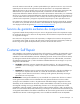
Serviço de garantia apenas para peças A garantia limitada da HP pode incluir um serviço de garantia apenas para peças. Segundo os termos do serviço de garantia apenas para peças, a HP fornece as peças de reposição sem cobrar nenhuma taxa. No caso desse serviço, a substituição de peças CSR é obrigatória. Se desejar que a HP substitua essas peças, serão cobradas as despesas de transporte e mão-de-obra do serviço.
Customer self repair 13
Customer self repair 14
Customer self repair 15
Customer self repair 16
Illustrated parts catalog Mechanical components Item Description Assembly part number Spare part number Customer self repair (on page 6) 1 Rack bezel, ProLiant DL580 G5 Server 443256-001 449431-001 Mandatory1 2 Access panel, ProLiant DL580 G5 Server 443254-001 449429-001 Mandatory1 3 Blank, hard drive 376383-001 392613-001 Mandatory1 4 Processor memory module assembly 013062-001 449415-001 Optional2 — Blank kit, ProLiant DL580 G5 Server * — 449433-001 Mandatory1 Illustrated pa
Item Description Assembly part number Spare part number Customer self repair (on page 6) 5 Blank, SAS cage 443259-001 — Mandatory1 6 Blank, tape drive 443262-001 — Mandatory1 7 Blank, power supply 440204-001 — Mandatory1 8 Tower bezel, ProLiant DL580 G5 Server * 443351-001 457900-001 Mandatory1 9 Tool, T-15 Torx * 107473-001 199630-001 Mandatory1 *Not shown 1 Mandatory—Parts for which customer self repair is mandatory.
HP realice su sustitución, puede o no conllevar costes adicionales, dependiendo del tipo de servicio de garantía correspondiente al producto. 3 No: No—Algunos componentes no están diseñados para que puedan ser reparados por el usuario. Para que el usuario haga valer su garantía, HP pone como condición que un proveedor de servicios autorizado realice la sustitución de estos componentes. Dichos componentes se identifican con la palabra “No” en el catálogo ilustrado de componentes.
System components Item Description Assembly part number Spare part number Customer self repair (on page 6) — System components — — — 1 Power supply, 1200 W 440785-001 441830-001 Mandatory1 2 Fan, 120-mm, hot-plug 439235-001 449430-001 Mandatory1 — Boards — — — 3 System board, ProLiant DL580 G5 Server 013059-001 449414-001 No3 4 Memory expansion board 013065-001 449416-001 Optional2 5 SPI board 013068-001 449417-001 Optional2 — System Insight Display — — — 6a Sy
Item Description Assembly part number Spare part number Customer self repair (on page 6) 7 Power backplane, ProLiant DL580 G5 Server 451885-001 449419-001 No3 8 SAS backplane 013151-001 449420-001 Optional2 9 Expansion slot options — — — — PCI-X 3 Slot Option Card 013081-001 449421-001 Optional2 — PCI Express x8 3 Slot Option Card 013084-001 449422-001 Optional2 10 PPM 450964-001 449428-001 Mandatory1 11 Smart Array cache module options — — — — Smart Array cache modu
Item Description Assembly part number Spare part number Customer self repair (on page 6) — Intel® Xeon® 2.4-GHz 16M 130W processor kit ** 481209-002 490065-001 Optional2 — Intel® Xeon® 2.13-GHz 12M 90W processor kit ** 493379-001 490066-001 Optional2 — Intel® Xeon® 2.13-GHz 8M 90W processor kit ** 493382-001 495179-001 Optional2 — Intel® Xeon® 2.
Item Description Assembly part number Spare part number Customer self repair (on page 6) — 120-GB, 5,400-rpm 431786-B21 431908-001 Mandatory1 *Not shown **When replacing the processor, you must also replace the heatsink (part number 453834-001). ***When replacing the processor, you must also replace the heatsink (part number 454594-001). 1 Mandatory—Parts for which customer self repair is mandatory.
Mandatory: Verplicht—Onderdelen waarvoor Customer Self Repair verplicht is. Als u HP verzoekt deze onderdelen te vervangen, komen de reiskosten en het arbeidsloon voor uw rekening. 2 Optional: Optioneel—Onderdelen waarvoor reparatie door de klant optioneel is. Ook deze onderdelen zijn ontworpen voor reparatie door de klant. Als u echter HP verzoekt deze onderdelen voor u te vervangen, kunnen daarvoor extra kosten in rekening worden gebracht, afhankelijk van het type garantieservice voor het product.
Removal and replacement procedures Required tools You need the following items for some procedures: • Torx T-15 screwdriver (provided with the server ("Rear panel components" on page 71)) • Phillips screwdriver • Flathead screwdriver • Diagnostics Utility Safety considerations Before performing service procedures, review all the safety information.
WARNING: To reduce the risk of electric shock or damage to the equipment: • Do not disable the power cord grounding plug. The grounding plug is an important safety feature. • Plug the power cord into a grounded (earthed) electrical outlet that is easily accessible at all times. • Unplug the power cord from the power supply to disconnect power to the equipment. • Do not route the power cord where it can be walked on or pinched by items placed against it.
IMPORTANT: If installing a hot-plug device, it is not necessary to power down the server. 1. Shut down the OS as directed by the OS documentation. 2. Press the Power On/Standby button to place the server in standby mode. When the server enters standby power mode, the system power LED changes to amber. 3. Disconnect the power cords. The system is now without power. Extending the server from the rack The design of the server enables you to access several components through the front of the server.
3. After performing the installation or maintenance procedure, slide the server into the rack by pressing the server rail-release latches. Removing the server from the rack WARNING: The server weighs approximately 36.3 kg–49.9 kg (80 lb–110 lb).
CAUTION: Do not operate the server for long periods with the access panel open or removed. Operating the server in this manner results in improper airflow and improper cooling that can lead to thermal damage. 1. Extend the server from the rack, if applicable ("Extending the server from the rack" on page 27). 2. Unlock the latch using a T-15 Torx screwdriver. NOTE: The T-15 Torx screwdriver is shipped with the server and can be located on the rear panel ("Rear panel components" on page 71). 3.
2. If the shipping screws are installed, remove them. The shipping screw locations are marked with tags on both sides of the server for easy identification. 3. Release the latches on the lever. 4. Lower the handle, and pull the processor memory module out of the server until the release latches catch.
5. Firmly holding the processor memory module, press the release buttons and pull the module out of the server. 6. Remove the processor memory module cover. To replace the component, reverse the removal procedure. Hard drive CAUTION: Always power down the server if the boot partition resides on the drive you are replacing or if you are replacing the only drive in the server.
2. Back up all data on the hard drive. 3. Remove the hard drive. To replace the component, reverse the removal procedure. Tape drive blank CAUTION: To prevent improper cooling and thermal damage, do not operate the server unless all bays are populated with either a component or a blank. Press the tabs, and pull out the blank. To replace the component, reverse the removal procedure.
Tape drive 1. Power down the server (on page 26). 2. Extend the server from the rack ("Extending the server from the rack" on page 27). 3. Remove the access panel ("Removing the access panel" on page 28). 4. Disconnect the data and power cables from the rear of the tape drive. 5. Push the tab, and pull out the tape drive. To replace the component, reverse the removal procedure. SAS drive cage blank Press the tabs, and pull out the blank.
Processor assembly WARNING: To reduce the risk of personal injury from hot surfaces, allow the heatsink to cool before touching it. IMPORTANT: When replacing the processor, you must also replace the heatsink. For information on ordering the heatsink, see the Illustrated Parts Catalog (on page 17). 1. Power down the server (on page 26). 2. Remove the processor memory module, and open the cover ("Removing the processor memory module" on page 29). 3. Unlock the processor retaining bracket. 4.
7. Assemble the processor and heatsink. a. Remove the thermal interface protective cover from the heatsink. b. Align the processor with the retainer on the heatsink. Be sure that the triangle printed on the corner of the processor aligns with the triangle on the retainer. c. Insert the processor into the retainer, and press down firmly until the processor clicks into place.
8. Align the guide pins on the base of the processor retaining bracket to the three corresponding guide slots on the processor assembly.
9. Insert the processor assembly into the processor socket, and close the locking lever. 10. Close and lock the processor retaining bracket. 11. Replace the processor memory module cover. 12. Install the processor memory module into the server. 13. Power up the server.
PPM IMPORTANT: Processor socket 1 and PPM slot 1 must be populated at all times or the server does not function properly. IMPORTANT: Always install a PPM when you install a processor. The system fails to boot if the PPM is missing. 1. Power down the server (on page 26). 2. Remove the processor memory module, and open the cover ("Removing the processor memory module" on page 29). 3. Remove the PPM. To replace the component, reverse the removal procedure. FBDIMMs 1. Power down the server (on page 26).
4. Remove the FBDIMM. To replace the component, reverse the removal procedure. Memory expansion boards 1. Power down the server (on page 26). 2. Remove the processor memory module, and open the cover ("Removing the processor memory module" on page 29). 3. Remove the memory expansion board. 4. Remove each FBDIMM ("FBDIMMs" on page 38), and install it in the same location on the new memory expansion board. 5. Install the memory expansion board in the same location on processor memory module.
Processor memory module To replace the processor memory module: 1. Power down the server (on page 26). WARNING: Use caution when installing the processor memory module or removing the processor memory module. The processor memory module is very heavy when fully populated. 2. Remove the processor memory module, and open the cover ("Removing the processor memory module" on page 29). 3.
7. Press the locking latch, and push the Systems Insight Display assembly through the front of the server. 8. Remove the DVD drive (on page 41) from the Systems Insight Display assembly, and then install the drive into the new assembly. 9. To replace the component, reverse the removal procedure. If a SATA DVD drive is installed, before installing the Systems Insight Display assembly into the server, route the cable through the open bay, and then connect the cable to the rear of the DVD drive.
o Pull the spring clip, and push the rear of the DVD drive through the front of the Systems Insight Display assembly. o If a SATA DVD drive is installed, lift the tab, and push the rear of the DVD drive through the front of the Systems Insight Display assembly.
7. To replace the component, reverse the removal procedure. If a SATA DVD drive is installed, before installing the Systems Insight Display assembly into the server, route the cable through the open bay, and then connect the cable to the rear of the DVD drive. Front bezel 1. Power down the server (on page 26). 2. Extend the server from the rack ("Extending the server from the rack" on page 27). 3. Remove the access panel ("Removing the access panel" on page 28). 4.
Power supply blank Press the tab, and remove the blank from the server. To replace the component, reverse the removal procedure. Power supplies IMPORTANT: If there are less than two power supplies installed, power down the server before removing the power supply. 1. Disconnect the power cord from the power supply. 2. Remove the power supply. To replace the component, reverse the removal procedure.
Fans IMPORTANT: Remove and replace one fan at a time. If the system detects two fan failures in the same zone, the server shuts down to avoid thermal damage. 1. Remove the access panel ("Removing the access panel" on page 28). 2. Remove the malfunctioning hot-plug fan from the server. To replace the component, reverse the removal procedure. Fan cable assembly lr WARNING: Use caution when installing the processor memory module or removing the processor memory module.
5. Remove the fans. 6. Disconnect and remove the fan cable assembly. 7. Install and route the new fan cable assembly (on page 84). 8. Install the cable tie around the cables and the bottom of the fan bay. 9. Pull the cable tie until the cables are secured against the fan bay. Do not over tighten the cable tie. 10. Position the cable tie so the locking mechanism is outside of the fan bay, and trim any excess. 11. Install the processor memory module into the server.
16. Install the processor memory module into the server. 17. Power up the server, and resume normal server operations. Non-hot-plug expansion boards CAUTION: To prevent improper cooling and thermal damage, do not operate the server unless all expansion slots have either an expansion slot cover or an expansion board installed. 1. Power down the server (on page 26). 2. Extend or remove the server from the rack ("Extending the server from the rack" on page 27). 3.
4. Open the latch, and remove the expansion slot cover. To replace the component, reverse the removal procedure. PCI-X or PCI Express x8 3 Slot Option Card 1. Power down the server (on page 26). 2. Extend or remove the server from the rack ("Extending the server from the rack" on page 27). 3. Remove the processor memory module ("Removing the processor memory module" on page 29). 4. Remove the access panel ("Removing the access panel" on page 28). 5.
Battery-backed write cache procedures Two types of procedures are provided for the BBWC option: • • Removal and replacement of failed components: o Removing the cache module ("Removing the BBWC cache module" on page 50) o Removing the battery pack ("Removing the BBWC battery pack" on page 49) Recovery of cached data from a failed server ("Recovering data from the battery-backed write cache" on page 51) CAUTION: Do not detach the cable that connects the battery pack to the cache module.
5. Press the tab, and remove the battery pack from the battery retainer. 6. Disconnect the cable from the cache module only if the battery pack is not being used to recover data from the server or transfer data to another server. To replace the component, reverse the removal procedure. After installing a battery pack, you might see a POST message during reboot indicating that the array accelerator (cache) is temporarily disabled.
4. If the bracket is installed, remove the bracket. 5. If the existing cache is connected to a battery, observe the BBWC Status LED ("Battery pack LEDs" on page 79). 6. o If the LED is blinking every 2 seconds, data is still trapped in the cache. Restore system power, and repeat the previous steps. o If the LED is not lit, disconnect the battery cable from the cache. Pull the cache module away from the SPI board. To replace the component, reverse the removal procedure.
CAUTION: Before starting this procedure, read the information about protecting against electrostatic discharge ("Preventing electrostatic discharge" on page 25). 1. 2. Perform one of the following: o Set up a recovery server station using an identical server model. Do not install any internal drives or BBWC in this server. (This is the preferred option.
4. If the bracket is installed, remove the bracket. 5. Locate the battery ("SPI board components" on page 76). 6. Remove the battery. To replace the component, reverse the removal procedure. Run the RBSU to configure the server after replacing the battery. See the HP ROM-Based Setup Utility User Guide on the Documentation CD for more detailed information. SPI board 1. Power down the server (on page 26). 2. Extend or remove the server from the rack ("Extending the server from the rack" on page 27).
5. If the bracket is installed, remove the bracket. 6. Disconnect all cables from the SPI board. IMPORTANT: If replacing the SPI board or clearing NVRAM, you must re-enter the server serial number through RBSU ("Re-entering the server serial number and product ID" on page 57). 7. Raise the levers, and lift the SPI board from the server. To replace the component, reverse the removal procedure.
WARNING: The server weighs approximately 36.3 kg–49.9 kg (80 lb–110 lb). To reduce the risk of injury due to the weight of the server, remove the following components before removing the server from the rack: • Processor memory module ("Removing the processor memory module" on page 29) • Hard drives ("Hard drive" on page 31) • Power supplies (on page 44) The server weighs 21.8 kg (48 lb) with these components removed and might require two people to remove the server from the rack.
6. If the bracket is installed, remove the bracket. 7. Loosen the thumbscrews, and remove the center bracket. 8. Remove the PCI-X or PCI Express x8 3 slot Option Card (on page 48), if installed. 9. Remove the SPI board (on page 53). 10. Disconnect all cables connected to the system board. 11. Remove the system board from the server. a. To release the handle, slide the latch toward the front of the server. b. Rotate the handle to an upright position. c.
d. Lift the system board from the server. To replace the component, reverse the removal procedure. Re-entering the server serial number and product ID After you replace the SPI board, you must re-enter the server serial number and the product ID. 1. During the server startup sequence, press the F9 key to access RBSU. 2. Select the Advanced Options menu. 3. Select Serial Number. The following warning is displayed: Warning: The serial number should ONLY be modified by qualified service personnel.
5. Disconnect all cables from the SAS backplane. 6. Slide the plastic retainer to the front of the server. 7. Lift the backplane, slide the board over the anchoring pins, and lift the board out of the server. To replace the component, reverse the removal procedure. Power backplane 1. Power down the server (on page 26). 2. Extend or remove the server from the rack ("Extending the server from the rack" on page 27). 3. Remove the access panel ("Removing the access panel" on page 28). 4.
9. Lift the backplane, slide the board over the anchoring pins, and lift the board out of the server. To replace the component, reverse the removal procedure.
Diagnostic tools SmartStart software SmartStart is a collection of software that optimizes single-server setup, providing a simple and consistent way to deploy server configuration. SmartStart has been tested on many ProLiant server products, resulting in proven, reliable configurations.
configuration information collected about your systems, ISEE enables fast restoration of your systems. Install ISEE on your systems to help mitigate risk and prevent potential critical problems. For more information on ISEE, refer to the HP website (http://www.hp.com/hps/hardware/hw_enterprise.html). To download HP ISEE, visit the HP website (http://www.hp.com/hps/hardware/hw_downloads.html). For installation information, refer to the HP ISEE Client Installation and Upgrade Guide (ftp://ftp.hp.
The ROMPaq utility checks the system and provides a choice (if more than one exists) of available firmware revisions. For more information about the ROMPaq utility, see the HP website (http://www.hp.com/go/support). System Online ROM flash component utility The Online ROM Flash Component Utility enables system administrators to efficiently upgrade system or controller ROM images across a wide range of servers and array controllers.
operating system. The iLO 2 subsystem provides remote access to any authorized network client, sends alerts, and provides other server management functions. Using iLO 2, you can: • Remotely power up, power down, or reboot the host server. • Send alerts from iLO 2 regardless of the state of the host server. • Access advanced troubleshooting features through the iLO 2 interface. • Diagnose iLO 2 using HP SIM through a web browser and SNMP alerting.
For more information or to download the utility, refer to the HP website (http://www.hp.com/servers/diags). USB support HP provides both standard USB support and legacy USB support. Standard support is provided by the operating system through the appropriate USB device drivers. HP provides support for USB devices before the operating system loads through legacy USB support, which is enabled by default in the system ROM. HP hardware supports USB version 1.1 or 2.0, depending on the version of the hardware.
IMPORTANT: Reboot the server after completing each numbered step. If the error condition continues, proceed with the next step. To troubleshoot processor-related error codes: 1. Bring the server to base configuration by removing all components that are not required by the server to complete POST.
IMPORTANT: Processor socket 1 and PPM slot 1 must be populated at all times or the server does not function properly. o PPMs ("PPM" on page 38), except the PPM installed in slot 1 o DIMMs ("FBDIMMs" on page 38), except the first bank o Hard drives ("Hard drive" on page 31) o Peripheral devices 3. Reseat the remaining memory boards, rebooting after each installation to isolate any failed memory boards, if applicable. 4. Replace the DIMMs with a remaining bank of memory. 5.
IMPORTANT: If replacing the system board or clearing NVRAM, you must re-enter the server serial number through RBSU ("Re-entering the server serial number and product ID" on page 57). Miscellaneous port 85 codes To troubleshoot all other port 85 codes: IMPORTANT: Reboot the server after completing each numbered step. If the error condition continues, proceed with the next step. 1. Bring the server to base configuration by removing all components that are not required by the server to complete POST.
Server component identification Front panel components Item Description 1 USB connectors 2 Video connector 3 Systems Insight Display 4 DVD drive bay 5 Optional tape drive or blank 6 Optional hard drive bay or blank 7 Hard drive bay 8 Processor memory module Server component identification 68
Front panel LEDs and buttons Item Description Status 1 UID switch and LED Blue—Activated Blue (flashing)—Server being managed remotely Off—Deactivated 2 Internal system health LED Green—Normal (system on) Amber (flashing)—Internal system health degraded Red (flashing)—Internal system health critical Off—Normal (system off) 3 External system health LED Green—Normal (system on) Amber (flashing)—External system health degraded Red (flashing)—External system health critical Off—Normal (system off)
Systems Insight Display The Systems Insight Display LEDs represent the server and component layout.
Rear panel components Item Description Item Description 1 Power supply bay 4 (optional) 13 PCI-X non-hot-plug for PCI Express x8 non-hotplug expansion slot 3 (optional) 2 Power supply bay 3 (optional) 14 PCI Express x8 non-hot-plug expansion slot 4 3 Power supply bay 2 15 PCI Express x8 non-hot-plug expansion slot 5 4 Power supply bay 1 16 PCI Express x8 non-hot-plug expansion slot 6 5 Keyboard connector 17 PCI Express x8 non-hot-plug expansion slot 7 6 USB connectors 18 PCI Expr
Rear panel LEDs and buttons Item Description LED color Status 1 NIC 2 Activity LED Green On or flashing—Network activity Off—No network activity 2 NIC 2 Link LED Green On—Linked to network Off—Not linked to network 3 UID Blue On—Front UID button activated Off—Normal 4 iLO 2 NIC Activity LED Green On or flashing—Network activity Off—No network activity 5 iLO 2 NIC Link LED Green On—Linked to network Off—Not linked to network 6 NIC 1 Link LED Green On—Linked to network Off—Not link
Power supply LED Power LED (green) Failure LED (amber) Status Off Off No AC power to power supply units On Off AC present. Standby output on.
System board components Item Description 1 Fan 1 2 Fan 2 3 Connector for: • PCI Express x8 3 Slot Option Card (optional) • PCI-X 3 Slot Option Card (optional) 4 Fan 3 5 Fan 5 6 Fan 4 7 Fan 6 8 PCI Express x8 non-hot-plug expansion slot 4 9 PCI Express x8 non-hot-plug expansion slot 5 10 PCI Express x8 non-hot-plug expansion slot 6 11 PCI Express x8 non-hot-plug expansion slot 7 12 PCI Express x4 non-hot-plug expansion slot 8 13 PCI Express x4 non-hot-plug expansion slot 9 14
Item Description 16 System maintenance switch (SW1) 17 Port 84/85 code display 18 SPI board System maintenance switch The system maintenance switch (SW1) is an eight-position switch that is used for system configuration. The switch 7 and switch 8 settings determine which codes display on the system board ("System board components" on page 74). The default position for all eight positions is Off.
SPI board components Item Description 1 BBWC cache module connectors 2 Battery FBDIMM slot locations The server contains 16 FBDIMM slots on the processor-memory board, which are numbered sequentially from 1 to 16. The paired banks are identified by the letters A through H. Four FBDIMM slots located on each optional memory board are numbered from 1 to 4. The paired banks are identified by the letters A through D.
See "Memory options" in the HP ProLiant DL580 Generation 5 User Guide for DIMM population guidelines.
SAS hard drive LEDs Item Description 1 Fault/UID LED (amber/blue) 2 Online LED (green) SAS hard drive LED combinations Online/activity LED (green) Fault/UID LED (amber/blue) On, off, or flashing Alternating amber and The drive has failed, or a predictive failure alert has been blue received for this drive; it also has been selected by a management application. On, off, or flashing Steadily blue The drive is operating normally, and it has been selected by a management application.
Online/activity LED (green) Fault/UID LED (amber/blue) Interpretation Flashing irregularly Off The drive is active, and it is operating normally. Off Steadily amber A critical fault condition has been identified for this drive, and the controller has placed it offline. Replace the drive as soon as possible. Off Amber, flashing regularly (1 Hz) A predictive failure alert has been received for this drive. Replace the drive as soon as possible.
LED3 pattern LED4 pattern Interpretation — One blink every two seconds The system is powered down, and the cache contains data that has not yet been written to the drives. Restore system power as soon as possible to prevent data loss. Data preservation time is extended any time that 3.3 V auxiliary power is available, as indicated by LED 2. In the absence of auxiliary power, battery power alone preserves the data. A fullycharged battery can normally preserve data for at least two days.
Fan locations Server component identification 81
Cabling BBWC cabling CAUTION: When routing cables, always be sure that the cables are not in a position where they can be pinched or crimped.
Hard drive cabling Cabling 83
Tape drive cabling Fan cable assembly SATA DVD drive cabling CAUTION: When routing cables, always be sure that the cables are not in a position where they can be pinched or crimped.
DVD drive cabling CAUTION: When routing cables, always be sure that the cables are not in a position where they can be pinched or crimped.
Specifications Environmental specifications Specification Value Temperature range* Operating 10°C to 35°C (50°F to 95°F) Shipping -40°C to 70°C (-40°F to 158°F) Maximum wet bulb temperature 28°C (82.4°F) Relative humidity (noncondensing)** Operating 10% to 90% Non-operating 5% to 95% * All temperature ratings shown are for sea level. An altitude derating of 1°C per 300 m (1.8°F per 1,000 ft) to 3048 m (10,000 ft) is applicable. No direct sunlight allowed.
Specification Value Power supply output 910 W (low line) 1300 W (high line) Specifications 87
Technical support Before you contact HP Be sure to have the following information available before you call HP: • Technical support registration number (if applicable) • Product serial number • Product model name and number • Product identification number • Applicable error messages • Add-on boards or hardware • Third-party hardware or software • Operating system type and revision level HP contact information For the name of the nearest HP authorized reseller: • See the Contact HP worldwi
Acronyms and abbreviations ABEND abnormal end ASR Automatic Server Recovery BBWC battery-backed write cache BIOS Basic Input/Output System CSA Canadian Standards Association DOS disk operating system FBDIMM fully buffered DIMM iLO 2 Integrated Lights-Out 2 IML Integrated Management Log ISEE Instant Support Enterprise Edition LED light-emitting diode NIC network interface controller Acronyms and abbreviations 89
NVRAM non-volatile memory ORCA Option ROM Configuration for Arrays OS operating system PCI peripheral component interface PCI-X peripheral component interconnect extended POST Power-On Self Test PPM processor power module RAID redundant array of inexpensive (or independent) disks RBSU ROM-Based Setup Utility ROM read-only memory SAS serial attached SCSI SATA serial ATA SCSI small computer system interface SDRAM synchronous dynamic RAM Acronyms and abbreviations 90
SFF small form-factor SIM Systems Insight Manager SNMP Simple Network Management Protocol SPI system peripheral interface UID unit identification USB universal serial bus Acronyms and abbreviations 91
Index A access panel 28 ASR (Automatic Server Recovery) 63 authorized reseller 88 Automatic Server Recovery (ASR) 63 Autorun menu 60 B backplane, hard drive 57 backplane, power 58 backplane, SAS 57 battery 52, 76 battery pack LEDs 79 battery-backed write cache (BBWC) 49, 50, 51, 76, 79, 82 battery-backed write cache battery pack 49 battery-backed write cache cabling 82 BBWC (battery-backed write cache) 49, 50, 51, 76, 79, 82 BBWC cabling 82 bezel, front 43 blank, hard drive cage 33 blank, power supply 44 b
front panel buttons 69 front panel components 68, 70 front panel LEDs 69 H hard drive backplane 57, 83 hard drive backplane cabling 83 hard drive bays 68, 77 hard drive cage blank 33 hard drive LEDs 78 hard drives 31 health driver 63 heatsink 34 help resources 88 HP Insight Diagnostics 63 HP Instant Support Enterprise Edition 60 HP ProLiant Essentials Foundation Pack 63 HP technical support 88 I illustrated parts catalog 17 iLO (Integrated Lights-Out) 62 iLO 2 (Integrated Lights-Out 2) 62 iLO 2 activity L
R rack, extending server from 27 rack, removing server from 28 RBSU (ROM-Based Setup Utility) 61 rear panel buttons 72 rear panel components 71 rear panel connectors 71 rear panel LEDs 72 recovering BBWC data 51 removal and replacement procedures 25 removing server from rack 28 removing the access panel 28 required information 88 required tools 25 requirements, environmental 86 ROM, updating 62 ROM-Based Setup Utility (RBSU) 61 ROMPaq utility 61 S safety considerations 25 safety information 25 SAS backplan