
ProLiant DL580 Generation 5 Maintenance and Service Guide


Removal and replacement procedures 40
Processor memory module
To replace the processor memory module:
1. Power down the server (on page 26).
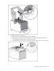
WARNING: Use caution when installing the processor memory module or removing the
processor memory module. The processor memory module is very heavy when fully populated.
2. Remove the processor memory module, and open the cover ("Removing the processor memory
module" on page 29).
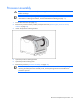
3. Remove each processor ("Processor assembly" on page 34), and install it in the same location in the
new processor memory module.
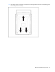
IMPORTANT: Be sure to install the processors in same location in the new processor memory
module. For example, the processor from socket 1 must be installed in socket 1 of the new
processor memory module. See the processor migration instructions that ship with the
processor memory module for more information.
4. Remove each PPM ("PPM" on page 38), and install it in the same location in the new processor
memory module.
5. Remove each memory expansion board ("Memory expansion boards" on page 39), and install it in
the same location in the new processor memory module.
6. Remove each FBDIMM ("FBDIMMs" on page 38), and install it in the same location in the new
processor memory module.
IMPORTANT: Be sure to install FBDIMMs in the same banks on the spare processor memory
module. For example, the FBDIMM from slot 1A must be installed in slot 1A in the new
processor memory module.
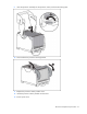
7. Close the processor memory module cover.
8. Install the processor memory module into the server.
9. Power up the server.
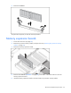
Systems Insight Display assembly
CAUTION: When routing cables, always be sure that the cables are not in a position where
they can be pinched or crimped.
1. Power down the server (on page 26).
2. Extend or remove the server from the rack ("Extending the server from the rack" on page 27).
3. Remove the access panel ("Removing the access panel" on page 28).
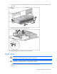
4. Remove the tape drive blank (on page 32), if installed.
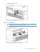
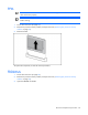
5. Remove the data cable connected to the rear of the Systems Insight Display assembly.
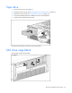
6. Remove the data and power cables connected to the DVD board of the System Insight Display
assembly. If a SATA DVD drive is installed, remove the cable connected to the rear of the DVD drive.