
Implementing SR-IOV on HP ProLiant Servers with VMware vSphere 5.1


Technical white paper | Implementing SR-IOV on HP ProLiant Servers with VMware vSphere
3
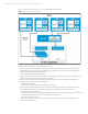
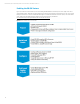
Figure 1 shows the PF and VF concepts on a 2-port, SR-IOV-capable network adapter.
Figure 1. SR-IOV PF and VF Conceptual Overview
When planning an SR-IOV implementation in vSphere 5.1, take into account the following key requirements, which are
addressed in more detail throughout the remainder of this paper.
• Each VF may utilize the entire potential bandwidth of a PF. There is not a method to provide priority or guaranteed
bandwidth to VFs. As a result, consideration of the following relationships is critical to a successful implementation:
– Determining the specific VMs that will utilize VFs
– Determining the specific VM and PF associations
• At least one PF must be reserved for use by a vSwitch or Distributed vSwitch. When configuring a PF for SR-IOV, the PF
cannot be chosen during creation and configuration of vSwitches.
• If network redundancy is required for a VM, then multiple VFs may be presented to a VM. Adhere to the following
configuration requirements to implement redundancy:
– Spread the VFs across PFs
– Configure network adapter teaming or bonding within the Guest OS.
• There are host and network adapter restrictions that limit the maximum number of VFs that each ESXi host supports.
Three interrelated factors define the number of VFs available for each ESXi host for presentation to VMs:
– Number of VFs configured by the user
The network adapter device driver parameters define the number of VFs to be presented by each port. The value must
not exceed the defined maximums of the other two factors described below.
– Number of VFs supported per port
Each network adapter has a maximum supported VF count per port. As an example, the HP 560M adapter has a
limitation of 63 VFs per port.