HP ProLiant DL580 Gen8 Server User Guide Abstract This document is for the person who installs, administers, and troubleshoots servers and storage systems. HP assumes you are qualified in the servicing of computer equipment and trained in recognizing hazards in products with hazardous energy levels.
© Copyright 2014 Hewlett-Packard Development Company, L.P. The information contained herein is subject to change without notice. The only warranties for HP products and services are set forth in the express warranty statements accompanying such products and services. Nothing herein should be construed as constituting an additional warranty. HP shall not be liable for technical or editorial errors or omissions contained herein. Microsoft®, Windows®, and Windows Server® are U.S.
Contents Component identification ............................................................................................................... 6 Front panel components ............................................................................................................................. 6 Front panel LEDs and buttons ...................................................................................................................... 7 Systems Insight Display .......................................
Powering on and selecting a boot option ................................................................................................... 38 Registering the server ............................................................................................................................... 38 Hardware options installation ....................................................................................................... 39 Introduction ................................................................
HP Smart Storage Administrator ...................................................................................................... 80 Option ROM Configuration for Arrays ............................................................................................. 81 ROMPaq utility .............................................................................................................................. 81 Automatic Server Recovery .......................................................................
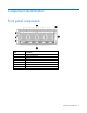
Component identification Front panel components Item Description 1 Drive bays 6-10* 2 Systems Insight Display 3 Fans 1-4 4 Drive bays 1-5 5 Discovery services connectors 6 Video connector 7 USB connectors (2) * Drives installed in these bays require the optional SAS backplane and cables.
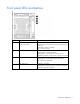
Front panel LEDs and buttons Item Description Status 1 Power on/Standby button and system power LED Solid green = System on Flashing green (1 Hz/cycle per sec) = Performing power on sequence Solid amber = System in standby Off = No power present 2 Health LED Solid green = Normal Flashing amber = System degraded Flashing red (1 Hz/cycle per sec) = System critical Fast-flashing red (4 Hz/cycles per sec) = System power fault 3 Aggregate NIC LED Solid green = Link to network Flashing green = Linked
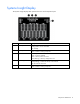
Systems Insight Display The Systems Insight Display LEDs represent the server and component layout.
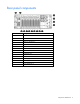
Rear panel components Item Description 1 Expansion board slot 1 2 Expansion board slot 2 3 Expansion board slot 3 4 Expansion board slot 4 5 Expansion board slot 5 6 Expansion board slot 6 7 Expansion board slot 7 8 Expansion board slot 8 9 Expansion board slot 9 10 FlexibleLOM slot 11 SPI board 12 Power supply 1 13 Power supply 2 14 Power supply bay 3 15 Power supply bay 4 Component identification 9
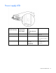
Power supply LED Fail LED-amber (Located on the SID) Power LED-green (Located on the power supply) Front external health LED Located on the front panel Status Off Off Off No AC power to power supply units Off Off Green AC present/Standby outputs on Power supply DC outputs on and OK On Off Amber (flashing) – redundant Red (flashing) – non-redundant Power supply failure (includes over voltage and over temperature) Component identification 10
I/O board components Item Description 1 NMI jumper 2 Slot 1 PCIe3 x16 (16, 8, 4, 2, 1) 3 Slot 2 PCIe3 x16 (16, 8, 4, 2, 1) 4 System maintenance switch 5 Slot 3 PCIe3 x16 (16, 8, 4, 2, 1) 6 Slot 4 PCIe3 x16 (8, 4, 2, 1) 7 Slot 5 PCIe3 x16 (8, 4, 2, 1) 8 Slot 6 PCIe3 x16 (16, 8, 4, 2, 1) 9 Slot 7 PCIe3 x16 (8, 4, 2, 1) 10 Slot 8 PCIe3 x16 (8, 4, 2, 1) 11 Slot 9 PCIe3 x16 (16, 8, 4, 2, 1) 12 SPI board connector 13 FlexibleLOM connector Component identification 11
System maintenance switch The system maintenance switch (SW1) is a twelve-position switch that is used for system configuration. The default position for all twelve positions is Off. Switch Settings 1 Off = iLO security enabled On = iLO security disabled 2 Off = Normal operation On = The BIOS configuration is locked. 5 Off = Normal operation On = Password disabled 6 Off = Normal operation On = Clear CMOS and RAM 7* Off = Set factory default boot mode to UEFI.
SPI board components Item Description 1 Top SAS backplane connector 2 SAS cache module connector 3 Systems Insight Display Power/UID connector 4 Internal USB connector 5 TPM connector 6 Front video/USB connector 7 Battery 8 Internal USB connector 9 Serial connector 10 Video connector 11 USB connectors (4) 12 iLO connector 13 FlexibleLOM port 1* 14 FlexibleLOM port 2* 15 FlexibleLOM port 3* 16 FlexibleLOM port 4* *Port configuration is dependent on the installed FlexibleLOM
Power daughter board components Item Description 1 Upper SAS backplane power connector 2 I/O board auxiliary power connector 3 I/O board auxiliary power connector 4 I/O board auxiliary power connector 5 I/O board auxiliary power connector 6 I/O board auxiliary power connector 7 I/O board auxiliary power connector 8 Power backplane data connector 9 Power backplane data connector 10 I/O board power connector Component identification 14
DIMM slot locations Each memory cartridge contains 12 DIMM slots. Install DIMMs in pairs in alphabetical order. For installation guidelines, see "Memory options (on page 47).
Processors and memory cartridges The processor memory drawer contains 4 processor sockets and 8 memory cartridges. For DIMM numbering, see "DIMM slot locations (on page 15)." For installation guidelines, see "Memory options (on page 47).
DIMM fault LEDs Item Description Status 1 Power fault LED (board B) Off = The DIMMs are operating normally. Solid amber = One or more DIMMs in the cartridge is experiencing a power fault condition. 2 General board fault LED (board B) Off = The DIMMs are operating normally. Solid amber = One or more DIMMs in the cartridge is experiencing a general fault condition. 3 General board fault LED (board A) Off = The DIMMs are operating normally.
DIMM fault identification button When the DIMM fault LEDs (on page 17) indicate that a DIMM is experiencing an error, press the DIMM fault identification button to illuminate the LED below the affected DIMM ("Memory error LEDs" on page 19).
Memory error LEDs When the DIMM fault LEDs (on page 17) indicate that a DIMM is experiencing an error, the memory error LED below the affected DIMM illuminates red when the DIMM fault identification button (on page 18) is pressed. Drive bay numbering Drives installed in bays 6-10 require the optional SAS backplane.
Hot-plug drive LED definitions Item LED Status Definition 1 Locate Solid blue The drive is being identified by a host application. Flashing blue The drive carrier firmware is being updated or requires an update. Rotating green Drive activity Off No drive activity Solid white Do not remove the drive. Removing the drive causes one or more of the logical drives to fail. Off Removing the drive does not cause a logical drive to fail.
FBWC capacitor slots Item Description 1 Slots 2-4—Connect to optional SAS controllers 2 Slot 1—Connects to the SPI board FBWC module LEDs The FBWC module has three single-color LEDs (one amber and two green). The LEDs are duplicated on the reverse side of the cache module to facilitate status viewing. 1 - Amber 2 - Green 3 - Green Interpretation Off Off Off The cache module is not powered.
1 - Amber 2 - Green 3 - Green Interpretation Off Off Flashing once per second The cache module is idle, and the capacitor pack is charging. Off Off On The cache module is idle, and the capacitor pack is charged. Off On On The cache module is idle, the capacitor pack is charged, and the cache contains data that has not yet been written to the drives. Off Flashing once per second Off A backup of the DDR content on the cache module is in progress.
Operations Power up the server To power up the server, press the Power On/Standby button. Power down the server WARNING: To reduce the risk of personal injury, electric shock, or damage to the equipment, remove the power cord to remove power from the server. The front panel Power On/Standby button does not completely shut off system power. Portions of the power supply and some internal circuitry remain active until AC power is removed.
2. Extend the server on the rack rails until the server rail-release latches engage. 3. After performing the installation or maintenance procedure, slide the server into the rack by pressing the server rail-release latches. Remove the server from the rack WARNING: To reduce the risk of personal injury or equipment damage, be sure that the rack is adequately stabilized before extending a component from the rack.
This symbol indicates that the component exceeds the recommended weight for one individual to handle safely. 32.18-52.87 kg WARNING: To reduce the risk of personal injury or damage to the equipment, observe 70.94-116.56 lb local occupational health and safety requirements and guidelines for manual material handling. To remove the server from the rack: 1. Pull down the quick-release levers on each side of the server to release the server from the rack. If necessary, loosen the rack screws. 2.
o Top loading telescoping rails o Front loading telescoping rails Operations 26
2. Slide the server into the rack by pressing the server rail-release latches. Remove the access panel WARNING: To reduce the risk of personal injury from hot surfaces, allow the drives and the internal system components to cool before touching them. CAUTION: Do not operate the server for long periods with the access panel open or removed. Operating the server in this manner results in improper airflow and improper cooling that can lead to thermal damage. To remove the component: 1.
Processor memory drawer shipping screw locations Two orange shipping screws secure the processor memory drawer in place during shipping. You must remove the screws to access the processor memory drawer. Retain the screws for future use. Remove the processor memory drawer WARNING: The processor memory drawer weighs more than 11.3 kg (25.0 lb). Use extra caution when removing and replacing the processor memory drawer. 1. Remove the processor memory drawer shipping screws, if installed.
4. Firmly holding the processor memory drawer, press the release buttons and then remove the drawer from the server. Remove the processor memory drawer cover 1. Remove the processor memory drawer shipping screws, if installed. Retain the screws for future use ("Processor memory drawer shipping screw locations" on page 28). 2. Remove the processor memory drawer (on page 28). 3. Remove the processor memory drawer cover. Access the Systems Insight Display To access the Systems Insight Display: 1.
2. After the display fully ejects, rotate the display to the left to view the LEDs. Remove the SPI board To remove the component: 1. Power down the server (on page 23). 2. Remove all power: a. Disconnect each power cord from the power source. b. Disconnect each power cord from the server. 3. Extend the server from the rack (on page 23). 4. Remove the access panel (on page 27). 5. Remove the processor memory drawer shipping screws, if installed.
6. Extend the processor memory drawer approximately 2.54-5.1 cm (1-2 inches). 7. Loosen the thumbscrews on the SPI board, and then lift the SPI board to access the cables. 8. Disconnect all cables from the SPI board. IMPORTANT: If replacing the SPI board or clearing NVRAM, you must re-enter the server serial number through the Advanced System ROM options in UEFI System Utilities ("Re-entering the server serial number and product ID" on page 80). 9. Remove the SPI board from the server.
Setup Optional installation services Delivered by experienced, certified engineers, HP Care Pack services help you keep your servers up and running with support packages tailored specifically for HP ProLiant systems. HP Care Packs let you integrate both hardware and software support into a single package. A number of service level options are available to meet your needs.
Space and airflow requirements To allow for servicing and adequate airflow, observe the following space and airflow requirements when deciding where to install a rack: • Leave a minimum clearance of 63.5 cm (25 in) in front of the rack. • Leave a minimum clearance of 76.2 cm (30 in) behind the rack. • Leave a minimum clearance of 121.9 cm (48 in) from the back of the rack to the back of another rack or row of racks.
CAUTION: To reduce the risk of damage to the equipment when installing third-party options: • Do not permit optional equipment to impede airflow around the server or to increase the internal rack temperature beyond the maximum allowable limits. • Do not exceed the manufacturer’s TMRA. Power requirements Installation of this equipment must comply with local and regional electrical regulations governing the installation of information technology equipment by licensed electricians.
WARNING: To reduce the risk of personal injury or damage to the equipment, be sure that: • • • • • The leveling jacks are extended to the floor. The full weight of the rack rests on the leveling jacks. The stabilizing feet are attached to the rack if it is a single-rack installation. The racks are coupled together in multiple-rack installations. Only one component is extended at a time. A rack may become unstable if more than one component is extended for any reason.
WARNING: To reduce the risk of electric shock, fire, or damage to the equipment, do not plug telephone or telecommunications connectors into RJ-45 connectors. 3. Connect the power cord to the rear of the server. 4. Install the power cord anchors. 5. Secure the cables to the cable management arm. IMPORTANT: When using cable management arm components, be sure to leave enough slack in each of the cables to prevent damage to the cables when the server is extended from the rack.
6. Connect the power cord to the AC power source. WARNING: To reduce the risk of electric shock or damage to the equipment: • Do not disable the power cord grounding plug. The grounding plug is an important safety feature. • Plug the power cord into a grounded (earthed) electrical outlet that is easily accessible at all times. • Unplug the power cord from the power supply to disconnect power to the equipment. • Do not route the power cord where it can be walked on or pinched by items placed against it.
• Intelligent Provisioning—iLO Management is a feature on ProLiant servers that contains Intelligent Provisioning for embedded server configuration, OS deployment, and provisioning capabilities. Intelligent Provisioning can configure the server and install an operating system, eliminates the need for SmartStart CDs and Smart Update Firmware DVDs used in past generations of HP ProLiant servers. To install an operating system on the server with Intelligent Provisioning (local or remote): a.
Hardware options installation Introduction If more than one option is being installed, read the installation instructions for all the hardware options and identify similar steps to streamline the installation process. WARNING: To reduce the risk of personal injury from hot surfaces, allow the drives and the internal system components to cool before touching them. CAUTION: To prevent damage to electrical components, properly ground the server before beginning any installation procedure.
Installing the processor The processors and memory are located in the drawer accessible from the front of the server. It is not necessary to extend or remove the server from the rack to install or replace processors and memory. WARNING: Use caution when installing or removing the processor memory drawer. The processor memory drawer is very heavy when fully populated.
7. Open each of the processor locking levers in the order indicated, and then open the processor retaining bracket. 8. Remove the clear processor socket cover. Retain the processor socket cover for future use.
9. Install the processor. Verify that the processor is fully seated in the processor retaining bracket by visually inspecting the processor installation guides on either side of the processor. THE PINS ON THE SYSTEM BOARD ARE VERY FRAGILE AND EASILY DAMAGED. CAUTION: THE PINS ON THE SYSTEM BOARD ARE VERY FRAGILE AND EASILY DAMAGED. To avoid damage to the system board, do not touch the processor or the processor socket contacts. 10. Close the processor retaining bracket.
12. Remove the thermal interface protective cover from the heatsink. CAUTION: To prevent the heatsink from tilting to one side during installation and removal procedures, use a diagonally opposite pattern (an “X” pattern) when loosening and tightening the two spring-loaded screws. To prevent the screws from breaking off, do not over-tighten the screws. A maximum torque of 0.45 N m (4 in-Ib) is set for the system. 13. Install the heatsink. 14. Install the processor memory drawer cover. 15.
18. Power up the server (on page 23). Memory cartridge option Memory cartridge population guidelines When installing memory cartridges, observe the following guidelines: • Memory cartridges installed without a corresponding processor are not utilized: o Processor 1 corresponds to memory cartridges 1 and 2. o Processor 2 corresponds to memory cartridges 3 and 4. o Processor 3 corresponds to memory cartridges 5 and 6. Memory cartridges 5 and 6 are not recognized if processor 3 is not installed.
6. Press the release button, and then lift the handles on the new memory cartridge. 7. Raise the lift tab on the new memory cartridge, and then open the cartridge. 8. Open the DIMM slot latches.
9. Install the DIMM. CAUTION: When closing the memory cartridge cover, be sure the plastic fingers under the cover do not catch on the top edge of the DIMMs. 10. Close the new memory cartridge. 11. While holding the baffle door open, install the new memory cartridge. 12. Install the processor memory drawer cover. 13. Install the processor memory drawer. 14. Connect each power cord to the server. 15. Connect each power cord to the power source. 16. Power up the server (on page 23).
Memory options IMPORTANT: This server does not support mixing LRDIMMs, RDIMMs, or UDIMMs. Attempting to mix any combination of these DIMMs can cause the server to halt during BIOS initialization. The memory subsystem in this server supports LRDIMMs and RDIMMs: • UDIMMs are not supported in this server. • LRDIMMs support higher densities than single- and dual-rank RDIMMs, and higher speeds than quad-rank RDIMMs.
DIMM type DIMM rank LRDIMM Quad-rank (32 GB)** 1 DIMM per channel 2 DIMMs per channel 3 DIMMs per channel 1600 1600 1333 * Low voltage ** Standard voltage Memory subsystem architecture The memory subsystem in this server is divided into channels. Each processor supports eight channels, and each channel supports three DIMM slots, as shown in the following table.
DIMM identification To determine DIMM characteristics, use the label attached to the DIMM and the following illustration and table. Item Description Definition 1 Size — 2 Rank 1R 2R 3R 4R 3 Data width x4 = 4-bit x8 = 8-bit 4 Voltage rating L = Low voltage (1.35V) U = Ultra low voltage (1.
Advanced Memory Protection options are configured in RBSU. If the requested AMP mode is not supported by the installed DIMM configuration, the server boots in Advanced ECC mode. For more information, see "HP ROM-Based Setup Utility." The server can operate in independent channel mode (performance) or combined channel mode (lockstep). Lockstep mode improves the system reliability and availability.
• Do not mix LRDIMMs and RDIMMs. • UDIMMs are not supported on this server. • When multiple processors are installed, HP recommends installing the DIMMs in sequential alphabetical order: 4A, 9B, 1C, 12D, and so on. For detailed memory configuration rules and guidelines, use the Online DDR3 Memory Configuration Tool on the HP website (http://www.hp.com/go/ddr3memory-configurator). DIMM speeds are supported as indicated in the following table.
b. Disconnect each power cord from the server. 3. Remove the processor memory drawer shipping screws, if installed. Retain the screws for future use ("Processor memory drawer shipping screw locations" on page 28). 4. Remove the processor memory drawer (on page 28). 5. Remove the processor memory drawer cover (on page 29). 6. Press the release button, and then lift the handles on the new memory cartridge. 7. Raise the lift tab on the new memory cartridge, and then open the cartridge. 8.
9. Install the DIMM. CAUTION: When closing the memory cartridge cover, be sure the plastic fingers under the cover do not catch on the top edge of the DIMMs. 10. Close the new memory cartridge. 11. While holding the baffle door open, install the new memory cartridge. 12. Install the processor memory drawer cover. 13. Install the processor memory drawer. 14. Connect each power cord to the server. 15. Connect each power cord to the power source. 16. Power up the server (on page 23).
SAS drive backplane option CAUTION: To prevent damage to electrical components, take the appropriate anti-static precautions before beginning any system installation. Improper grounding can cause electrostatic discharge. To install the component: 1. Power down the server (on page 23). 2. Remove all power: a. Disconnect each power cord from the power source. b. Disconnect each power cord from the server. 3. Remove the access panel (on page 27). 4. Extend the processor memory drawer approximately 2.
6. Install the backplane, and then tighten the thumbscrews. 7. Connect the data cable.
8. Connect the power cable. 9. Install the SPI board. 10. Install the processor memory drawer. 11. Install the access panel. 12. Remove all bezel blanks.
13. Install the drives. 14. Install blanks in unused drive bays. 15. Connect each power cord to the server. 16. Connect each power cord to the power source. SAS controller cable option The SAS controller cable option is required to enable a PCIe slot-based controller to drive the internal top bay drives. Otherwise, the drive indicator signaling will not correctly match the accessed drive. The bottom bay SAS drives cannot be controlled by a PCIe slot-based controller.
4. Install the backplane, and then tighten the thumbscrews. 5. Connect the optional SAS controller cable.
6. Connect the power cable. 7. Install the access panel. 8. Remove all bezel blanks. 9. Install the drives.
10. Install blanks in unused drive bays. 11. Connect each power cord to the server. 12. Connect each power cord to the power source. Drive option When adding hard drives to the server, observe the following general guidelines: • The system automatically sets all device numbers. • If only one hard drive is used, install it in the bay with the lowest device number. • Hard drives must be SFF types.
2. Install the drive. 3. Determine the status of the drive from the hot-plug SAS drive LED combinations ("Hot-plug drive LED definitions" on page 20).
Installing the 4U rack bezel Redundant hot-plug power supply option The server supports up to four hot-plug power supplies. Install all power supplies to provide full redundancy. HP recommends installing redundant hot-plug power supplies in pairs. To confirm the redundancy of your configuration, see the HP power advisor at the HP website (http://www.hp.com/go/hppoweradvisor). WARNING: To reduce the risk of electric shock or damage to the equipment: • Do not disable the power cord grounding plug.
1. Remove the power supply blank. 2. Slide the power supply into the power supply bay until the device locks into place. 3. Connect the power cord to the power supply. 4. Connect the power cord to the power source. 5. Be sure that the power supply LED is green. 6. Be sure that the front panel external health LED is green ("Front panel LEDs and buttons" on page 7). Expansion board option The server ships with 9 PCI Express expansion slots.
a. Disconnect each power cord from the power source. b. Disconnect each power cord from the server. 3. Extend or remove the server from the rack. 4. Remove the access panel (on page 27). 5. Open the expansion board retainer, and then remove the expansion slot cover. 6. Remove the PCI retainer screw.
7. Install the expansion board. 8. Close the expansion slot retainer. 9. Connect any required internal or external cables to the expansion board. 10. Install the access panel. 11. Install the server in the rack. 12. Connect each power cord to the server. 13. Connect each power cord to the power source. 14. Resume normal server operations. FBWC module and capacitor pack option CAUTION: The cache module connector does not use the industry-standard DDR3 mini-DIMMs.
7. Remove the SPI board (on page 30). 8. Install the cache module. 9. Connect the cable.
10. Install the capacitor pack. 11. Install the SPI board. 12. Install the access panel. 13. Slide the server back into the rack. 14. Power up the server (on page 23). HP Trusted Platform Module option For more information about product features, specifications, options, configurations, and compatibility, see the product QuickSpecs on the HP Product Bulletin website (http://www.hp.com/go/productbulletin). Use these instructions to install and enable a TPM on a supported server.
• When returning a system board for service replacement, do not remove the TPM from the system board. When requested, HP Service provides a TPM with the spare system board. • Any attempt to remove an installed TPM from the system board breaks or disfigures the TPM security rivet. Upon locating a broken or disfigured rivet on an installed TPM, administrators should consider the system compromised and take appropriate measures to ensure the integrity of the system data.
6. Install the TPM board. Press down on the connector to seat the board. 7. Install the TPM security rivet by pressing the rivet firmly into the system board. 8. Install the SPI board. 9. Install the access panel. 10. Slide the server back into the rack. 11. Power up the server (on page 23). Enabling the Trusted Platform Module 1. During POST, press the F9 key to access System Configuration, and then select RBSU. 2. From the Main Menu, select Server Security. 3.
7. Reboot the server. 8. Enable the TPM in the OS. For OS-specific instructions, see the OS documentation. CAUTION: When a TPM is installed and enabled on the server, data access is locked if you fail to follow the proper procedures for updating the system or option firmware, replacing the system board, replacing a hard drive, or modifying OS application TPM settings.
Cabling Server cabling Item Description 1 Standby power cable 2 Power supply data cable 3 Front video/USB cable 4 Systems Insight Display cable Cabling 71
Software and configuration utilities Server mode The software and configuration utilities presented in this section operate in online mode, offline mode, or in both modes.
iLO enables and manages the Active Health System (on page 73) and also features Agentless Management. All key internal subsystems are monitored by iLO. SNMP alerts are sent directly by iLO regardless of the host operating system or even if no host operating system is installed. HP Insight Remote Support software (on page 76) is also available in HP iLO with no operating system software, drivers, or agents.
The data that is collected is managed according to the HP Data Privacy policy. For more information see the HP website (http://www.hp.com/go/privacy). The Active Health System log, in conjunction with the system monitoring provided by Agentless Management or SNMP Pass-thru, provides continuous monitoring of hardware and configuration changes, system status, and service alerts for various server components. The Agentless Management Service is available in the SPP, which is a disk image (.
see the Resources tab on the HP website (http://www.hp.com/go/ilo). For consolidated drive and firmware update packages, see the HP Systems and Server Software Management page on the HP website (http://www.hp.com/go/SmartUpdate).
HP Insight Remote Support software HP strongly recommends that you register your device for remote support to enable enhanced delivery of your HP Warranty, HP Care Pack Service, or HP contractual support agreement.
• Update drivers, utilities, and firmware on ProLiant servers using the SPP • Configure ProLiant system hardware, iLOs, BIOS, and HP SmartArray • Deploy to target servers with or without PXE (HP ProLiant Gen8 and later) • Run deployment jobs on multiple servers simultaneously • Customize your HP ProLiant deployments with an easy to use browser-based interface For more information about Insight Control server provisioning, see the HP website (http://www.hp.com/go/insightcontrol).
For more information or to download SPP, see one of the following pages on the HP website: • HP Service Pack for ProLiant download page (http://www.hp.com/go/spp) • HP Systems and Server Software Management page (http://www.hp.com/go/SmartUpdate) HP Smart Update Manager HP SUM is a product used to install and update firmware, drivers, and systems software on HP ProLiant servers.
• After defaults have been restored Default configuration settings are sufficient for typical server operations; however, you can modify configuration settings as needed. The system prompts you for access to the System Utilities each time the system is powered up. Flexible boot control This feature enables you to do the following: • Add Boot Options o Browse all FAT16 and FAT32 file systems. o Select an X64 UEFI application with an .
• OS UEFI boot loaders Once enabled, only firmware components and operating systems with boot loaders that have an appropriate digital signature can execute during the boot process. Only operating systems that support Secure Boot and have an EFI boot loader signed with one of the authorized keys can boot when Secure Boot is enabled. For more information about supported operating systems, see the HP UEFI System Utilities Release Notes on the HP website (http://www.hp.com/go/uefi/docs).
HP SSA exists in three interface formats: the HP SSA GUI, the HP SSA CLI, and HP SSA Scripting. Although all formats provide support for configuration tasks, some of the advanced tasks are available in only one format.
Automatic Server Recovery ASR is a feature that causes the system to restart when a catastrophic operating system error occurs, such as a blue screen, ABEND (does not apply to HP ProLiant DL980 Servers), or panic. A system fail-safe timer, the ASR timer, starts when the System Management driver, also known as the Health Driver, is loaded. When the operating system is functioning properly, the system periodically resets the timer.
IMPORTANT: Always perform a backup before installing or updating device drivers. The server includes new hardware that may not have driver support on all OS installation media. If you are installing an Intelligent Provisioning-supported OS, use Intelligent Provisioning (on page 74) and its Configure and Install feature to install the OS and latest supported drivers. If you do not use Intelligent Provisioning to install an OS, drivers for some of the new hardware are required.
HP Technology Service Portfolio HP Technology Services offers a targeted set of consultancy, deployment, and service solutions to meet the support needs of most business and IT environments. Foundation Care services—Delivers scalable hardware and software support packages for HP ProLiant server and industry-standard software. You can choose the type and level of service that is most suitable for your business needs.
Troubleshooting Troubleshooting resources The HP ProLiant Gen8 Troubleshooting Guide, Volume I: Troubleshooting provides procedures for resolving common problems and comprehensive courses of action for fault isolation and identification, issue resolution, and software maintenance on ProLiant servers and server blades. To view the guide, select a language: • English (http://www.hp.com/support/ProLiant_TSG_v1_en) • French (http://www.hp.com/support/ProLiant_TSG_v1_fr) • Spanish (http://www.hp.
Battery replacement If the server no longer automatically displays the correct date and time, you may need to replace the battery that provides power to the real-time clock. Under normal use, battery life is 5 to 10 years. WARNING: The computer contains an internal lithium manganese dioxide, a vanadium pentoxide, or an alkaline battery pack. A risk of fire and burns exists if the battery pack is not properly handled. To reduce the risk of personal injury: • • • • Do not attempt to recharge the battery.
IMPORTANT: To avoid a mismatch between boot modes, HP recommends setting system maintenance switch 7 to the same BIOS boot mode the server is deployed in. Otherwise, the storage controller may not recognize the OS installed on the storage media. For more information, see "System Maintenance Switch (on page 12)." To replace the component, reverse the removal procedure. For more information about battery replacement or proper disposal, contact an authorized reseller or an authorized service provider.
Regulatory information Safety and regulatory compliance For safety, environmental, and regulatory information, see Safety and Compliance Information for Server, Storage, Power, Networking, and Rack Products, available at the HP website (http://www.hp.com/support/Safety-Compliance-EnterpriseProducts). Belarus Kazakhstan Russia marking Manufacturer Hewlett-Packard Company, Address: 3000 Hanover Street, Palo Alto, California 94304, U.S.
Valid date formats include the following: • YWW, where Y indicates the year counting from within each new decade, with 2000 as the starting point. For example, 238: 2 for 2002 and 38 for the week of September 9. In addition, 2010 is indicated by 0, 2011 by 1, 2012 by 2, 2013 by 3, and so forth. • YYWW, where YY indicates the year, using a base year of 2000. For example, 0238: 02 for 2002 and 38 for the week of September 9.
Electrostatic discharge Preventing electrostatic discharge To prevent damaging the system, be aware of the precautions you need to follow when setting up the system or handling parts. A discharge of static electricity from a finger or other conductor may damage system boards or other static-sensitive devices. This type of damage may reduce the life expectancy of the device. To prevent electrostatic damage: • Avoid hand contact by transporting and storing products in static-safe containers.
Specifications Environmental specifications Specification Value Temperature range* Operating 10°C to 35°C (50°F to 95°F) Shipping -40°C to 70°C (-40°F to 158°F) Maximum wet bulb temperature 28°C (82.4°F) Relative humidity (noncondensing)** Operating 10% to 90% Nonoperating 5% to 95% * All temperature ratings shown are for sea level. An altitude derating of 1°C per 300 m (1.8°F per 1,000 ft) to 3,048 m (10,000 ft) is applicable. No direct sunlight allowed.
HP 1200 W Common Slot Platinum Plus Hot-Plug Power Supply (94% efficiency) Specification Value Input requirements Rated input voltage 100 VAC,100 to 120 VAC Rated input frequency 50 Hz to 60 Hz Rated input current 9.2 A at 100 VAC 9.5 A at 110 to 120 VAC 6.
input Specifications 93
Support and other resources Before you contact HP Be sure to have the following information available before you call HP: • Active Health System log (HP ProLiant Gen8 or later products) Download and have available an Active Health System log for 3 days before the failure was detected. For more information, see the HP iLO 4 User Guide or HP Intelligent Provisioning User Guide on the HP website (http://www.hp.com/go/ilo/docs).
providers or service partners) identifies that the repair can be accomplished by the use of a CSR part, HP will ship that part directly to you for replacement. There are two categories of CSR parts: • Mandatory—Parts for which customer self repair is mandatory. If you request HP to replace these parts, you will be charged for the travel and labor costs of this service. • Optional—Parts for which customer self repair is optional. These parts are also designed for customer self repair.
Pour plus d'informations sur le programme CSR de HP, contactez votre Mainteneur Agrée local. Pour plus d'informations sur ce programme en Amérique du Nord, consultez le site Web HP (http://www.hp.com/go/selfrepair). Riparazione da parte del cliente Per abbreviare i tempi di riparazione e garantire una maggiore flessibilità nella sostituzione di parti difettose, i prodotti HP sono realizzati con numerosi componenti che possono essere riparati direttamente dal cliente (CSR, Customer Self Repair).
HINWEIS: Einige Teile sind nicht für Customer Self Repair ausgelegt. Um den Garantieanspruch des Kunden zu erfüllen, muss das Teil von einem HP Servicepartner ersetzt werden. Im illustrierten Teilekatalog sind diese Teile mit „No“ bzw. „Nein“ gekennzeichnet. CSR-Teile werden abhängig von der Verfügbarkeit und vom Lieferziel am folgenden Geschäftstag geliefert. Für bestimmte Standorte ist eine Lieferung am selben Tag oder innerhalb von vier Stunden gegen einen Aufpreis verfügbar.
sustituciones que lleve a cabo el cliente, HP se hará cargo de todos los gastos de envío y devolución de componentes y escogerá la empresa de transporte que se utilice para dicho servicio. Para obtener más información acerca del programa de Reparaciones del propio cliente de HP, póngase en contacto con su proveedor de servicios local. Si está interesado en el programa para Norteamérica, visite la página web de HP siguiente (http://www.hp.com/go/selfrepair).
Opcional – Peças cujo reparo feito pelo cliente é opcional. Essas peças também são projetadas para o reparo feito pelo cliente. No entanto, se desejar que a HP as substitua, pode haver ou não a cobrança de taxa adicional, dependendo do tipo de serviço de garantia destinado ao produto. OBSERVAÇÃO: Algumas peças da HP não são projetadas para o reparo feito pelo cliente. A fim de cumprir a garantia do cliente, a HP exige que um técnico autorizado substitua a peça.
Support and other resources 100
Support and other resources 101
Acronyms and abbreviations ABEND abnormal end ACU Array Configuration Utility AMP Advanced Memory Protection ASR Automatic Server Recovery BBWC battery-backed write cache CSA Canadian Standards Association DDDC Double Device Data Correction ESD electrostatic discharge FBWC flash-backed write cache IEC International Electrotechnical Commission iLO 4 Integrated Lights-Out 4 IML Integrated Management Log Acronyms and abbreviations 102
KVM keyboard, video, and mouse NVRAM nonvolatile memory ORCA Option ROM Configuration for Arrays PCIe Peripheral Component Interconnect Express PCI-X peripheral component interconnect extended PDU power distribution unit PID port ID POST Power-On Self Test QPI QuickPath Interconnect RAS Reliability, Availability, Serviceability RBSU ROM-Based Setup Utility SAS serial attached SCSI SD Secure Digital SDDC Single Device Data Correction Acronyms and abbreviations 103
SFF small form factor SIM Systems Insight Manager SMI Scalable memory interfaces SPI system peripheral interface SPP HP Service Pack for ProLiant TMRA recommended ambient operating temperature TPM Trusted Platform Module UEFI Unified Extensible Firmware Interface UID unit identification UPS uninterruptible power system USB universal serial bus VCA Version Control Agent Acronyms and abbreviations 104
Documentation feedback HP is committed to providing documentation that meets your needs. To help us improve the documentation, send any errors, suggestions, or comments to Documentation Feedback (mailto:docsfeedback@hp.com). Include the document title and part number, version number, or the URL when submitting your feedback.
Index A access panel 27 ACU (Array Configuration Utility) airflow requirements 32, 33 Array Configuration Utility (ACU) ASR (Automatic Server Recovery) authorized reseller 94 Automatic Server Recovery (ASR) D 72, 80 80 82 82 B Basic Input/Output System (BIOS) 72, 81 battery 86 battery replacement notice 88 battery warranty 89 Belarus Kazakhstan Russia marking 88 bezel, rack 61, 62 BIOS (Basic Input/Output System) 72, 81 BIOS upgrade 72, 81 board, SPI (System Peripheral Interface) 30 boot options 38 BSMI n
front panel components 6 front panel LEDs 7 limited warranty 89 load protection guarantee 89 G M grounding methods 90 grounding requirements 34 memory 48, 49, 50 memory cartridge 16, 44 memory cartridge population guidelines 44 memory configurations 49, 50 memory error LEDs 19 memory options 47 memory subsystem architecture 48 memory, Advanced ECC 50 memory, configuring 50 memory, online spare 50 modifications, FCC notice 88 H hard drive LEDs 20 hard drives, determining status of 20 hardware options 3
processor memory drawer cover 29 processor memory drawer shipping screws 28 processors 16 product information resources 72 Q QuickSpecs 72 R rack bezel 61 rack installation 32, 34 rack mounting hardware 35 rack resources 32 rack warnings 34 rack, extending server from 23 RAID configuration 80 RBSU (ROM-Based Setup Utility) 72 rear panel components 9 recommended ambient operating temperature (TMRA) 33 recovery key 68 redundant ROM 82 registering the server 38 regulatory compliance identification numbers 88
W warranty 89 website, HP 94 Index 109