HP ProLiant DL585 Generation 5 Server Maintenance and Service Guide Part Number 463283-006 September 2009 (Sixth Edition)
© Copyright 2007, 2009 Hewlett-Packard Development Company, L.P. The information contained herein is subject to change without notice. The only warranties for HP products and services are set forth in the express warranty statements accompanying such products and services. Nothing herein should be construed as constituting an additional warranty. HP shall not be liable for technical or editorial errors or omissions contained herein. Microsoft, Windows, NT, and Windows Server are U.S.
Contents Customer self repair ...................................................................................................................... 6 Parts only warranty service ......................................................................................................................... 6 Illustrated parts catalog ............................................................................................................... 17 Mechanical components..............................................
Diagnostic tools .......................................................................................................................... 60 SmartStart software ................................................................................................................................. 60 SmartStart Scripting Toolkit ....................................................................................................................... 60 HP Insight Remote Support software .............................
Index.........................................................................................................................................
Customer self repair HP products are designed with many Customer Self Repair (CSR) parts to minimize repair time and allow for greater flexibility in performing defective parts replacement. If during the diagnosis period HP (or HP service providers or service partners) identifies that the repair can be accomplished by the use of a CSR part, HP will ship that part directly to you for replacement. There are two categories of CSR parts: • Mandatory—Parts for which customer self repair is mandatory.
Obligatoire - Pièces pour lesquelles la réparation par le client est obligatoire. Si vous demandez à HP de remplacer ces pièces, les coûts de déplacement et main d'œuvre du service vous seront facturés. Facultatif - Pièces pour lesquelles la réparation par le client est facultative. Ces pièces sont également conçues pour permettre au client d'effectuer lui-même la réparation.
NOTA: alcuni componenti HP non sono progettati per la riparazione da parte del cliente. Per rispettare la garanzia, HP richiede che queste parti siano sostituite da un centro di assistenza autorizzato. Tali parti sono identificate da un "No" nel Catalogo illustrato dei componenti. In base alla disponibilità e alla località geografica, le parti CSR vengono spedite con consegna entro il giorno lavorativo seguente.
anrufen und sich von einem Mitarbeiter per Telefon helfen lassen. Den Materialien, die mit einem CSRErsatzteil geliefert werden, können Sie entnehmen, ob das defekte Teil an HP zurückgeschickt werden muss. Wenn es erforderlich ist, das defekte Teil an HP zurückzuschicken, müssen Sie dies innerhalb eines vorgegebenen Zeitraums tun, in der Regel innerhalb von fünf (5) Geschäftstagen.
Centro de asistencia técnica de HP y recibirá ayuda telefónica por parte de un técnico. Con el envío de materiales para la sustitución de componentes CSR, HP especificará si los componentes defectuosos deberán devolverse a HP. En aquellos casos en los que sea necesario devolver algún componente a HP, deberá hacerlo en el periodo de tiempo especificado, normalmente cinco días laborables. Los componentes defectuosos deberán devolverse con toda la documentación relacionada y con el embalaje de envío.
bijbehorende documentatie worden geretourneerd in het meegeleverde verpakkingsmateriaal. Als u het defecte onderdeel niet terugzendt, kan HP u voor het vervangende onderdeel kosten in rekening brengen. Bij reparatie door de klant betaalt HP alle verzendkosten voor het vervangende en geretourneerde onderdeel en kiest HP zelf welke koerier/transportonderneming hiervoor wordt gebruikt. Neem contact op met een Service Partner voor meer informatie over het Customer Self Repair programma van HP.
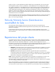
Serviço de garantia apenas para peças A garantia limitada da HP pode incluir um serviço de garantia apenas para peças. Segundo os termos do serviço de garantia apenas para peças, a HP fornece as peças de reposição sem cobrar nenhuma taxa. No caso desse serviço, a substituição de peças CSR é obrigatória. Se desejar que a HP substitua essas peças, serão cobradas as despesas de transporte e mão-de-obra do serviço.
Customer self repair 13
Customer self repair 14
Customer self repair 15
Customer self repair 16
Illustrated parts catalog Mechanical components Item Description Assembly part number Spare part number Customer self repair (on page 6) 1 Access panel 367572-002 419905-001 Mandatory1 2 Blank, media drive 377569-001 409006-001 Mandatory1 — Bezel kit — 419897-001 Mandatory1 3 Front bezel 414072-001 — Mandatory1 4 Power assembly bezel 414073-001 — Mandatory1 — Bezel kit, processor memory module* — 419904-001 Mandatory1 5 Processor memory module fan bezel 414122-001 — M
Optional—Parts for which customer self repair is optional. These parts are also designed for customer self repair. If, however, you require that HP replace them for you, there may or may not be additional charges, depending on the type of warranty service designated for your product. 3 No—Some HP parts are not designed for customer self repair. In order to satisfy the customer warranty, HP requires that an authorized service provider replace the part.
Mandatory: Obrigatória—Peças cujo reparo feito pelo cliente é obrigatório. Se desejar que a HP substitua essas peças, serão cobradas as despesas de transporte e mão-de-obra do serviço. 2 Optional: Opcional—Peças cujo reparo feito pelo cliente é opcional. Essas peças também são projetadas para o reparo feito pelo cliente. No entanto, se desejar que a HP as substitua, pode haver ou não a cobrança de taxa adicional, dependendo do tipo de serviço de garantia destinado ao produto.
System components Item Description Assembly part number Spare part number Customer self repair (on page 6) 1 Power supply, 910–1300 W 337867-501 406421-001 Mandatory1 2 System cage — — No3 3 Fan, 120 mm, hot-plug 364517-001 374552-001 Mandatory1 Boards 4 System board 013241-001 463751-001 No3 5 Power supply backplane 013263-001 501572-001 No3 6 Pass-through board 012896-001 419621-001 Mandatory1 7 Media board with System Insight Display LEDs 012668-001 419619-001 Opti
Item Description Assembly part number Spare part number Customer self repair (on page 6) Processor options 13 Heatsink 415651-001 419898-001 Optional2 14 AMD Opteron™ 8347HE 1.9-GHz 55W processor kit 448209-002 457127-001 Optional2 — AMD Opteron™ 8350 2.0-GHz 75W processor kit* 448208-004 457129-001 Optional2 — AMD Opteron™ 8354 2.2-GHz 95W processor kit* 448208-002 448404-001 Optional2 — AMD Opteron™ 8356 2.
Item Description Assembly part number Spare part number Customer self repair (on page 6) — DIMM, PC2-6400, 1 GB, 128Mx8* 499275-061 501156-001 Mandatory1 — DIMM, PC2-5300, 2 GB, 128Mx4* (dual rank) 405476-051 432668-001 Mandatory1 — DIMM, PC2-6400, 2 GB, 256Mx4* 499276-061 501157-001 Mandatory1 — DIMM, PC2-5300, 4 GB, 256Mx4* (dual rank) 405477-061 432670-001 Mandatory1 — DIMM, PC2-6400, 4 GB, 256Mx4* 499277-061 501158-001 Mandatory1 — DIMM, PC2-5300, 8 GB, 512Mx4* 405478-071
Item Description Assembly part number Spare part number Customer self repair (on page 6) — Blank, power supply* 366450-002 — Mandatory1 *Not shown 1 Mandatory—Parts for which customer self repair is mandatory. If you request HP to replace these parts, you will be charged for the travel and labor costs of this service. 2 Optional—Parts for which customer self repair is optional. These parts are also designed for customer self repair.
Mandatory: Verplicht—Onderdelen waarvoor Customer Self Repair verplicht is. Als u HP verzoekt deze onderdelen te vervangen, komen de reiskosten en het arbeidsloon voor uw rekening. 2 Optional: Optioneel—Onderdelen waarvoor reparatie door de klant optioneel is. Ook deze onderdelen zijn ontworpen voor reparatie door de klant. Als u echter HP verzoekt deze onderdelen voor u te vervangen, kunnen daarvoor extra kosten in rekening worden gebracht, afhankelijk van het type garantieservice voor het product.
Removal and replacement procedures Required tools You need the following items for some procedures: • Torx T-15 screwdriver (provided with the server ("Rear panel components" on page 73)) • Phillips screwdriver • Flathead screwdriver • Diagnostics Utility Safety considerations Before performing service procedures, review all the safety information.
WARNING: To reduce the risk of personal injury from hot surfaces, allow the drives and the internal system components to cool before touching them. CAUTION: Do not operate the server for long periods with the access panel open or removed. Operating the server in this manner results in improper airflow and improper cooling that can lead to thermal damage.
Extending the server from the rack The design of the server enables you to access several components through the front of the server. Installing or accessing the following components will not require extending the server from the rack: • Processors • PPMs • Processor memory board • DIMMs • DVD drive • Optional diskette or CD-ROM drive • Hard drives To extend the server from the rack: 1. Pull down the quick-release levers on each side of the server to release the server from the rack. 2.
3. After performing the installation or maintenance procedure, slide the server into the rack by pressing the server rail-release latches. Remove the server from the rack To remove the server from an HP, Compaq branded, telco, or third-party rack: 1. Power down the server (on page 26). 2. Extend the server from the rack ("Extending the server from the rack" on page 27). 3. Disconnect the cabling and remove the server from the rack.
3. Lift up on the hood latch, and remove the access panel. 4. After installing hardware options, replace the access panel. Be sure that the panel is securely locked into place before powering up the server. Removing the processor memory module The processors and memory are stored in a module at the front of the server.
WARNING: Use caution when installing the processor memory module or removing the processor memory module; when fully populated, it can weigh up to 13.6 kg (30 lb). 4. Firmly holding the processor memory module, press the release buttons and pull the module out of the server. 5. Remove the fans installed in the cover of the processor memory module. 6. Release the latch, and open the cover.
7. Close the processor memory module cover. To replace the component, reverse the removal procedure. Power button assembly bezel WARNING: Use caution when installing the processor memory module or removing the processor memory module; when fully populated, it can weigh up to 13.6 kg (30 lb). 1. Remove the processor memory module ("Removing the processor memory module" on page 29). 2. Press the tab and pull the bezel away from the server. To replace the component, reverse the removal procedure.
USB cable assembly 1. Power down the server (on page 26). 2. Remove the processor memory module ("Removing the processor memory module" on page 29). 3. Extend or remove the server from the rack ("Remove the server from the rack" on page 28, "Extending the server from the rack" on page 27). 4. Remove the access panel ("Removing the access panel" on page 28). 5. Remove the power button assembly bezel (on page 31). 6.
7. Remove the screws securing the cable bracket to the server and remove the bracket. 8. Remove the screws securing the video cable to the bracket and remove the cable. To replace the component, reverse the removal procedure. Power button cable assembly 1. Power down the server (on page 26). 2. Remove the processor memory module ("Removing the processor memory module" on page 29). 3.
7. Push up on the power button cable assembly to disconnect it from the server. 8. Pull the power button cable assembly away from the server. To replace the component, reverse the removal procedure. Fan cage bezel 1. Power down the server (on page 26). WARNING: Use caution when installing the processor memory module or removing the processor memory module; when fully populated, it can weigh up to 13.6 kg (30 lb). 2.
Processor memory module bezel 1. Power down the server (on page 26). 2. Remove the processor memory module, and open the cover ("Removing the processor memory module" on page 29). 3. Press the tabs to disconnect the bottom of the bezel and pull the bezel away from the server. If necessary, use a flathead screwdriver to press the tabs. To replace the component, reverse the removal procedure.
3. Open the heatsink retaining bracket. 4. Remove the heatsink.
5. Open the processor retaining latch and the processor socket retaining bracket. 6. Using your fingers, remove the failed processor. IMPORTANT: Be sure the replacement processor remains inside the processor installation tool.
7. If the processor has separated from the installation tool, carefully re-insert the processor in the tool. 8. Align the processor installation tool with the socket and install the spare processor. CAUTION: The processor is designed to fit one way into the socket. Use the alignment guides on the processor and socket to properly align the processor with the socket.
9. Press down firmly until the processor installation tool clicks and separates from the processor, and then remove the processor installation tool. 10. Close the processor retaining latch and the processor socket retaining bracket. 11. Clean the old thermal grease from the heatsink with the alcohol swab. Allow the alcohol to evaporate before continuing.
12. Apply all the grease to the top of the processor in one of the following patterns to ensure even distribution. 13. Install the heatsink.
14. Close the heatsink retaining bracket. 15. Close the processor memory module cover. 16. Install the fans. 17. Install the processor memory module into the server. 18. Power up the server. PPM Server PPMs provide the proper power to each processor. Each PPM must be installed in the slot adjacent to its processor. CAUTION: Processor and PPM sockets 1 and 2 must be populated at all times or the server will not function properly. IMPORTANT: Always install a PPM when you install a processor.
3. Remove the PPM. NOTE: The appearance of compatible PPMs may vary. To replace the component, reverse the removal procedure. NOTE: The PPM is keyed and the key must be aligned when installed. DIMMs 1. Power down the server (on page 26). 2. Remove the processor memory module, and open the cover ("Removing the processor memory module" on page 29). 3. Open the DIMM slot latches.
4. Remove the DIMM ("DIMMs" on page 42). To replace the component, reverse the removal procedure. Processor memory module To replace the processor memory module: 1. Power down the server (on page 26). WARNING: Use caution when installing the processor memory module or removing the processor memory module; when fully populated, it can weigh up to 13.6 kg (30 lb). 2. Remove the processor memory module, and open the cover ("Removing the processor memory module" on page 29). 3.
9. Power up the server. IMPORTANT: To prevent damage to the processor socket pins during shipment, install the processor socket covers before the defective processor memory module is shipped to HP. SAS or SATA hard drives CAUTION: Always power down the server if the boot partition resides on the drive you are replacing or if you are replacing the only drive in the server.
To replace the component, reverse the removal procedure. Power supply blank Press the handle and pull the power supply blank from the server. To replace the component, reverse the removal procedure. Power supply WARNING: To reduce the risk of electric shock, do not disassemble the power supply or attempt to repair it. Replace it only with the specified spare part. CAUTION: If only one power supply is installed, do not remove the power supply unless the server has been powered down.
immediate power loss. CAUTION: To prevent improper cooling and thermal damage, do not operate the server unless all bays are populated with either a component or a blank. NOTE: Refer to the section "Power supply LEDs ("Hot-plug power supply LEDs" on page 74)" for information on the current status of the hot-plug power supply. 1. Disconnect the power cord from the power supply. 2. Remove the power supply.
4. Remove the malfunctioning hot-plug fan from the server. IMPORTANT: Remove and replace one fan at a time. If the system detects two fan failures, the server shuts down to avoid thermal damage. 5. Install a new hot-plug fan. 6. Observe the LED on each installed fan to be sure it is illuminated green ("Hot-plug fan LEDs" on page 82). NOTE: If the front panel internal system health LED is not green after you install hot-plug fans, reseat the hot-plug fan or refer to the troubleshooting section. 7.
4. Open the latch, and remove the expansion slot cover. To replace the component, reverse the removal procedure.
Slot Description 7 PCI Express x8 non-hot-plug expansion slot (full-length) 8 PCI Express x8 non-hot-plug expansion slot (full-length) 9 PCI Express x4 non-hot-plug expansion slot (half-length) To remove a non-hot-plug expansion board: 1. Power down the server (on page 26). 2. Extend or remove the server from the rack ("Remove the server from the rack" on page 28, "Extending the server from the rack" on page 27). 3. Remove the access panel ("Removing the access panel" on page 28). 4.
7. Lift the backplane, slide the board over the anchoring pins, and lift the board out of the server. To replace the component, reverse the removal procedure. Pass-through board 1. Power down the server (on page 26). 2. Extend the server from the rack ("Extending the server from the rack" on page 27). 3. Remove the access panel ("Removing the access panel" on page 28). 4. Loosen the thumbscrews and lift the pass-through board out of the server.
2. Remove all media drives and media drive blanks ("Diskette, DVD, CD-RW drive, or blank" on page 44). 3. Extend the server from the rack ("Extending the server from the rack" on page 27). 4. Remove the access panel ("Removing the access panel" on page 28). 5. Remove the pass-through board ("Pass-through board" on page 50). 6. Disconnect all cabling from the media board. 7. Loosen the thumbscrew and slide the media board toward the front of the server. 8.
1. Power down the server (on page 26). 2. Extend the server from the rack ("Extending the server from the rack" on page 27). 3. Remove the access panel ("Removing the access panel" on page 28). CAUTION: Disconnect the cable from the cache module only if the battery pack is not being used to recover data from the server or transfer data to another server. 4. 5. If the existing cache is connected to a battery, observe the BBWC Status LED ("Battery pack LEDs" on page 80).
6. Remove the cache module from the controller. To replace the component, reverse the removal procedure. BBWC battery pack 1. Power down the server (on page 26). 2. Extend or remove the server from the rack ("Remove the server from the rack" on page 28, "Extending the server from the rack" on page 27). 3. Remove the access panel ("Removing the access panel" on page 28).
4. Remove the BBWC battery pack ("BBWC battery pack" on page 53). 5. Disconnect the cable from the cache module only if the battery pack is not being used to recover data from the server or transfer data to another server. CAUTION: Do not detach the cable that connects the battery pack to the cache module. Detaching the cable causes any unsaved data in the cache module to be lost. To replace the component, reverse the removal procedure. IMPORTANT: The battery pack might have a low charge when installed.
2. Power down the failed server ("Power down the server" on page 26). If any data is trapped in the cache module, an amber LED on the module blinks every 15 seconds. CAUTION: Do not detach the cable that connects the battery pack to the cache module. Detaching the cable causes any unsaved data in the cache module to be lost. 3. Transfer the hard drives from the failed server to the recovery server station. 4.
To replace the component, reverse the removal procedure. Power supply backplane 1. Power down the server (on page 26). 2. Remove the server from the rack (on page 28). 3. Remove the access panel ("Removing the access panel" on page 28). 4. Remove all hot-plug power supplies ("Power supply" on page 45). 5. Remove fans 3 through 6 installed in front of the power supply cages ("Fan locations" on page 81). 6. Remove all expansion boards ("Expansion boards" on page 48). 7.
11. Loosen the thumbscrew and remove the backplane. System board CAUTION: Before starting this procedure, read the information about protecting against electrostatic discharge ("Preventing electrostatic discharge" on page 25). CAUTION: Only authorized technicians trained by HP should attempt to remove the system board. If you believe the system board requires replacement, contact HP Technical Support ("HP contact information" on page 88) before proceeding.
12. Slide the system board out through the back of the server. IMPORTANT: If replacing the system board or clearing NVRAM, you must re-enter the server serial number through RBSU ("Re-entering the server serial number and product ID" on page 58). To replace the component, reverse the removal procedure. Re-entering the server serial number and product ID After you replace the system board, you must re-enter the server serial number and the product ID. 1.
CAUTION: Before starting this procedure, read the information about protecting against electrostatic discharge ("Preventing electrostatic discharge" on page 25). If the server no longer automatically displays the correct date and time, you may need to replace the battery that provides power to the real-time clock. Under normal use, battery life is 5 to 10 years. WARNING: The computer contains an internal lithium manganese dioxide, a vanadium pentoxide, or an alkaline battery pack.
Diagnostic tools SmartStart software SmartStart is a collection of software that optimizes single-server setup, providing a simple and consistent way to deploy server configuration. SmartStart has been tested on many ProLiant server products, resulting in proven, reliable configurations.
thousands of companies around the world. In many cases, you can avoid problems before they occur. There are two HP Insight Remote Support solutions: • For small and midsize environments: HP Insight Remote Support Standard provides basic remote monitoring, notification/advisories and service dispatch. It is optimized for environments with 1 to 50 servers and can be installed on a shared HP ProLiant Windows application server.
• Selecting the primary boot controller • Configuring memory options • Language selection For more information on RBSU, see the HP ROM-Based Setup Utility User Guide on the Documentation CD or the HP website (http://www.hp.com/support/smartstart/documentation). ROMPaq utility The ROMPaq utility enables you to upgrade the system firmware (BIOS). To upgrade the firmware, insert a ROMPaq diskette into the diskette drive or ROMPaq USB Key into an available USB port and boot the system.
o For Linux: IML Viewer Application • From within the iLO 2 user interface • From within HP Insight Diagnostics (on page 64) For more information, refer to the Management CD in the HP ProLiant Essentials Foundation Pack. Integrated Lights-Out 2 technology The iLO 2 subsystem is a standard component of selected ProLiant servers that provides server health and remote server manageability. The iLO 2 subsystem includes an intelligent microprocessor, secure memory, and a dedicated network interface.
HP Insight Diagnostics HP Insight Diagnostics is a proactive server management tool, available in both offline and online versions, that provides diagnostics and troubleshooting capabilities to assist IT administrators who verify server installations, troubleshoot problems, and perform repair validation. HP Insight Diagnostics Offline Edition performs various in-depth system and component testing while the OS is not running. To run this utility, launch the SmartStart CD.
Processor-related port 85 codes Processor-related port 85 codes display in the format 3xh. IMPORTANT: Reboot the server after completing each numbered step. If the error condition continues, proceed with the next step. To troubleshoot processor-related error codes: 1. Bring the server to base configuration by removing all components that are not required by the server to complete POST.
o Expansion boards (on page 48) o Processors (on page 35), except the processor installed in socket 1 IMPORTANT: Processor socket 1 and PPM slot 1 must be populated at all times or the server does not function properly. o PPMs ("PPM" on page 41), except the PPM installed in slot 1 o DIMMs (on page 42), except the first bank o Hard drives ("SAS or SATA hard drives" on page 44) o Peripheral devices 3.
IMPORTANT: If replacing the system board or clearing NVRAM, you must re-enter the server serial number through RBSU ("Re-entering the server serial number and product ID" on page 58). Miscellaneous port 85 codes To troubleshoot all other port 85 codes: IMPORTANT: Reboot the server after completing each numbered step. If the error condition continues, proceed with the next step. 1. Bring the server to base configuration by removing all components that are not required by the server to complete POST.
Component identification Front panel components Item Description 1 Hard drive bay 1 2 Hard drive bay 2 3 Hard drive bay 3 4 Hard drive bay 4 5 Hard drive bay 5 6 Hard drive bay 6 7 Hard drive bay 7 8 Hard drive bay 8 9 Video connector 10 USB connectors (two) 11 Media drive blank or optional media drive 12 DVD drive 13 Processor memory module Component identification 68
Front panel LEDs and buttons Item Description Status 1 UID switch and LED Blue = Activated Flashing blue = Server managed remotely Off = Deactivated 2 Internal system health LED Green = Normal (system on) Flashing amber = System health degraded Flashing red = System health critical Off = Normal (system off) 3 External system health LED Green = Normal (system on) Flashing amber = System health degraded Flashing red = System health critical Off = Normal (system off) 4 NIC 1 link/activity LED Gr
Processor memory module components Item Description 1 Processor socket 1 (boot processor) 2 PPM socket 1 3 Processor socket 3 4 PPM socket 3 5 Processor socket 4 6 PPM socket 4 7 Processor socket 2 8 PPM socket 2 See "Processor options" in the HP ProLiant DL585 Generation 5 Server User Guide for population guidelines.
DIMM slot identification Each memory node consists of eight DIMM slots in four banks. See "Memory options" in the HP ProLiant DL585 Generation 5 Server User Guide for DIMM population guidelines.
Item Description Status of an array Off = No drive activity SAS and SATA hard drive LED combinations Online/activity LED (green) Fault/UID LED (amber/blue) Interpretation On, off, or flashing Alternating amber and blue The drive has failed, or a predictive failure alert has been received for this drive; it also has been selected by a management application. On, off, or flashing Steadily blue The drive is operating normally, and it has been selected by a management application.
Rear panel components Item Description 1 Redundant hot-plug power supply (optional) 2 PCI Express and PCI-X non-hot-plug expansion slots 3 Hot-plug power supply (primary) 4 T-15 Torx screwdriver 5 NIC connector 1 6 NIC connector 2 7 iLO 2 connector 8 Serial connector 9 USB connectors (two) 10 Keyboard connector 11 Mouse connector 12 Video connector 13 Rear UID button and LED See "Expansion boards (on page 48)" for expansion slot definitions.
Rear panel LEDs and buttons Item Description LED color Status 1 UID LED Blue On = Activated Flashing = Server remotely managed Off = Deactivated 2 Activity LED Green On or flashing = Network activity Off = No network activity 3 Link LED Green On = Linked to network Off = Not linked to network Hot-plug power supply LEDs Component identification 74
Fail LED 1 (amber) Power LED 2 (green) Description Off Off No AC power to any power supply Flashing Off Power supply failure (over current) On Off No AC power to this power supply Off Flashing • • Off On AC power present Standby mode Normal Internal components Item Description 1 PCI-X non-hot-plug expansion slot 1, 64-bit/100-MHz (half-length) 2 PCI-X non-hot-plug expansion slot 2, 64-bit/100-MHz (full-length) 3 PCI Express x4 non-hot-plug expansion slot 3 (fulllength) 4 PCI Exp
Item Description length) 10 System battery 11 System maintenance switch (SW3) 12 Fan 6 connector 13 Fan 5 connector 14 Media board 15 Fan 1 connector 16 Fan 2 connector 17 BBWC battery pack 18 Fan 3 connector 19 Fan 4 connector System maintenance switch (SW3) The system maintenance switch (SW3) is an eight-position switch that is used for system configuration. The default position for all eight positions is Off (closed).
Position Description Function 5 Password protection override Off = Password is enabled. Configuration validation Off = Switch has no function. 6 On = Password is disabled. On = Setting clears CMOS and NVRAM. 7 Reserved Reserved 8 Reserved Reserved When the system maintenance switch position 6 is set to the On position, the system is prepared to erase all system configuration settings from both CMOS and NVRAM. CAUTION: Clearing CMOS and/or NVRAM deletes configuration information.
Boot device selector switch (SW1) The boot device selector switch setting determines the device access order of the media drives in the server. The default setting for the boot device selector switch is FLP TOP. When the boot device selector switch is set to FLP TOP, the optical drive in the bottom bay is designated as the primary optical drive. The diskette drive in the top bay is bootable.
NOTE: The system management driver must be installed for the internal system health LED to provide pre-failure and warranty conditions.
Battery pack LEDs Item ID Color Description 1 Green System Power LED. This LED glows steadily when the system is powered up and 12 V system power is available. This power supply is used to maintain the battery charge and provide supplementary power to the cache microcontroller. 2 Green Auxiliary Power LED. This LED glows steadily when 3.3V auxiliary voltage is detected.
LED3 pattern LED4 pattern Interpretation capacity expansion, stripe size migration, and RAID migration) are temporarily unavailable until charging is complete. The recharge process takes between 15 minutes and two hours, depending on the initial capacity of the battery. — Steady glow The battery pack is fully charged, and posted write data is stored in the cache. — Off The battery pack is fully charged, and there is no posted write data in the cache.
See "Hot-plug fans (on page 46)" for replacement procedures and operation guidelines.
Cabling BBWC cabling Front panel cable components Item Description 1 Video connector cable assembly 2 USB connector cable assembly Cabling 83
Item Description 3 Power button cable assembly SAS and SATA hard drive data cable routing CAUTION: When routing cables, always be sure that the cables are not in a position where they can be pinched or crimped. NOTE: The SAS power cable is not shown.
CAUTION: When routing cables, always be sure that the cables are not in a position where they can be pinched or crimped. NOTE: The SAS data cables are not shown.
Specifications Environmental specifications Specification Value Temperature range* Operating 10°C to 35°C (50°F to 95°F) Shipping -40°C to 70°C (-40°F to 158°F) Maximum wet bulb temperature 28°C (82.4°F) Relative humidity (noncondensing)** Operating 10% to 90% Non-operating 5% to 95% * All temperature ratings shown are for sea level. An altitude derating of 1°C per 300 m (1.8°F per 1,000 ft) to 3048 m (10,000 ft) is applicable. No direct sunlight allowed.
Specification Value BTUs per hour @100 VAC–3960 BTU @200 VAC–5450 BTU Power supply output Power supply output 910 W (low line) 1300 W (high line) Specifications 87
Technical support Before you contact HP Be sure to have the following information available before you call HP: • Technical support registration number (if applicable) • Product serial number • Product model name and number • Product identification number • Applicable error messages • Add-on boards or hardware • Third-party hardware or software • Operating system type and revision level HP contact information For the name of the nearest HP authorized reseller: • See the Contact HP worldwi
Acronyms and abbreviations ABEND abnormal end AMD Advanced Micro Devices ASR Automatic Server Recovery BBWC battery-backed write cache BIOS Basic Input/Output System CSR Customer Self Repair DIMM dual inline memory module DOS disk operating system iLO 2 Integrated Lights-Out 2 IML Integrated Management Log ISEE Instant Support Enterprise Edition NIC network interface controller Acronyms and abbreviations 89
NiMH nickel metal hydride NVRAM non-volatile memory ORCA Option ROM Configuration for Arrays OS operating system PCI-X peripheral component interconnect extended POST Power-On Self Test PPM processor power module RAID redundant array of inexpensive (or independent) disks RBSU ROM-Based Setup Utility RILOE II Remote Insight Lights-Out Edition II ROM read-only memory SAS serial attached SCSI SATA serial ATA SCSI small computer system interface Acronyms and abbreviations 90
SIM Systems Insight Manager SNMP Simple Network Management Protocol TDP Thermal Design Power UID unit identification UPS uninterruptible power system USB universal serial bus Acronyms and abbreviations 91
Index A access panel 28 adapter LEDs 69, 74 ASR (Automatic Server Recovery) 63 authorized reseller 88 Automatic Server Recovery (ASR) 63 Autorun menu 60 B backplane, power supply 56 backplane, SAS 49 Basic Input/Output System (BIOS) 62 battery 58, 75 battery pack LEDs 80 battery-backed write cache (BBWC) 51, 53, 54, 75, 80, 83 battery-backed write cache battery pack 51, 53, 75 battery-backed write cache cabling 83 BBWC (battery-backed write cache) 51, 53, 54, 75, 80, 83 bezel, fan 34 bezel, power button as
external power connector 73 F fan bezel 34 fan connectors 75 fan LED 78, 82 fans 46, 81, 82 features 68 front panel buttons 69 front panel components 68, 69 front panel LEDs 69, 78 H hard drive bays 68 hard drive LEDs 71, 72 hard drives 44, 68, 72 hard drives, determining status of 71, 72 health driver 63 HP Insight Diagnostics 64 HP Insight Remote Support software 60 HP ProLiant Essentials Foundation Pack 63 HP Systems Insight Manager, overview 63 HP technical support 88 HP, contacting 88 I illustrated
power button cabling 77, 83 power button LED 69 power connectors, external 73 power connectors, internal 75 Power On/Standby button 26, 69 power supply 45, 73, 74 power supply backplane 56 power supply blank 45 power supply LEDs 74 powering down 26 PPM (processor power module) 41, 70 preparation procedures 26 processor memory module 29, 43, 68, 70 processor memory module bezel 35 Processor Power Module (PPM) 41, 70 processor socket 35, 70 processor-related port 85 codes 65 processors 35, 70 R rack, extendi