HP ProLiant DL585 Generation 5 Server User Guide Part Number 463282-002 September 2009 (Second Edition)
© Copyright 2007, 2009 Hewlett-Packard Development Company, L.P. The information contained herein is subject to change without notice. The only warranties for HP products and services are set forth in the express warranty statements accompanying such products and services. Nothing herein should be construed as constituting an additional warranty. HP shall not be liable for technical or editorial errors or omissions contained herein. Microsoft, Windows, and Windows NT are U.S.
Contents Component identification ............................................................................................................... 6 Front panel components ............................................................................................................................. 6 Front panel LEDs and buttons ...................................................................................................................... 7 Processor memory module components ............................
Processor options .................................................................................................................................... 32 Removing the processor memory module .......................................................................................... 32 Installing a processor ..................................................................................................................... 34 Memory options ....................................................................
Pre-diagnostic steps ................................................................................................................................. 65 Important safety information............................................................................................................ 65 Symptom information ..................................................................................................................... 67 Prepare the server for diagnosis ............................................
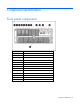
Component identification Front panel components Item Description 1 Hard drive bay 1 2 Hard drive bay 2 3 Hard drive bay 3 4 Hard drive bay 4 5 Hard drive bay 5 6 Hard drive bay 6 7 Hard drive bay 7 8 Hard drive bay 8 9 Video connector 10 USB connectors (two) 11 Media drive blank or optional media drive 12 DVD drive 13 Processor memory module Component identification 6
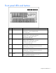
Front panel LEDs and buttons Item Description Status 1 UID switch and LED Blue = Activated Flashing blue = Server managed remotely Off = Deactivated 2 Internal system health LED Green = Normal (system on) Flashing amber = System health degraded Flashing red = System health critical Off = Normal (system off) 3 External system health LED Green = Normal (system on) Flashing amber = System health degraded Flashing red = System health critical Off = Normal (system off) 4 NIC 1 link/activity LED Gr
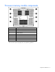
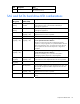
Processor memory module components Item Description 1 Processor socket 1 (boot processor) 2 PPM socket 1 3 Processor socket 3 4 PPM socket 3 5 Processor socket 4 6 PPM socket 4 7 Processor socket 2 8 PPM socket 2 See "Processor options (on page 32)" for population guidelines.
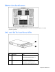
DIMM slot identification Each memory node consists of eight DIMM slots in four banks. See "Memory options" for DIMM population guidelines.
Item Description Status of an array Off = No drive activity SAS and SATA hard drive LED combinations Online/activity LED (green) Fault/UID LED (amber/blue) Interpretation On, off, or flashing Alternating amber and blue The drive has failed, or a predictive failure alert has been received for this drive; it also has been selected by a management application. On, off, or flashing Steadily blue The drive is operating normally, and it has been selected by a management application.
Rear panel components Item Description 1 Redundant hot-plug power supply (optional) 2 PCI Express and PCI-X non-hot-plug expansion slots 3 Hot-plug power supply (primary) 4 T-15 Torx screwdriver 5 NIC connector 1 6 NIC connector 2 7 iLO 2 connector 8 Serial connector 9 USB connectors (two) 10 Keyboard connector 11 Mouse connector 12 Video connector 13 Rear UID button and LED See "Expansion boards (on page 46)" for expansion slot definitions.
Rear panel LEDs and buttons Item Description LED color Status 1 UID LED Blue On = Activated Flashing = Server remotely managed Off = Deactivated 2 Activity LED Green On or flashing = Network activity Off = No network activity 3 Link LED Green On = Linked to network Off = Not linked to network Hot-plug power supply LEDs Component identification 12
Fail LED 1 (amber) Power LED 2 (green) Description Off Off No AC power to any power supply Flashing Off Power supply failure (over current) On Off No AC power to this power supply Off Flashing • • Off On AC power present Standby mode Normal Internal components Item Description 1 PCI-X non-hot-plug expansion slot 1, 64-bit/100-MHz (half-length) 2 PCI-X non-hot-plug expansion slot 2, 64-bit/100-MHz (full-length) 3 PCI Express x4 non-hot-plug expansion slot 3 (fulllength) 4 PCI Exp
Item Description length) 10 System battery 11 System maintenance switch (SW3) 12 Fan 6 connector 13 Fan 5 connector 14 Media board 15 Fan 1 connector 16 Fan 2 connector 17 BBWC battery pack 18 Fan 3 connector 19 Fan 4 connector System maintenance switch (SW3) The system maintenance switch (SW3) is an eight-position switch that is used for system configuration. The default position for all eight positions is Off (closed).
Position Description Function 5 Password protection override Off = Password is enabled. Configuration validation Off = Switch has no function. 6 On = Password is disabled. On = Setting clears CMOS and NVRAM. 7 Reserved Reserved 8 Reserved Reserved When the system maintenance switch position 6 is set to the On position, the system is prepared to erase all system configuration settings from both CMOS and NVRAM. CAUTION: Clearing CMOS and/or NVRAM deletes configuration information.
Boot device selector switch (SW1) The boot device selector switch setting determines the device access order of the media drives in the server. The default setting for the boot device selector switch is FLP TOP. When the boot device selector switch is set to FLP TOP, the optical drive in the bottom bay is designated as the primary optical drive. The diskette drive in the top bay is bootable.
NOTE: The system management driver must be installed for the internal system health LED to provide pre-failure and warranty conditions.
Battery pack LEDs Item ID Color Description 1 Green System Power LED. This LED glows steadily when the system is powered up and 12 V system power is available. This power supply is used to maintain the battery charge and provide supplementary power to the cache microcontroller. 2 Green Auxiliary Power LED. This LED glows steadily when 3.3V auxiliary voltage is detected.
LED3 pattern LED4 pattern Interpretation capacity expansion, stripe size migration, and RAID migration) are temporarily unavailable until charging is complete. The recharge process takes between 15 minutes and two hours, depending on the initial capacity of the battery. — Steady glow The battery pack is fully charged, and posted write data is stored in the cache. — Off The battery pack is fully charged, and there is no posted write data in the cache.
See "Hot-plug fans (on page 29)" for replacement procedures and operation guidelines.
Setup Optional installation services Delivered by experienced, certified engineers, HP Care Pack services help you keep your servers up and running with support packages tailored specifically for HP ProLiant systems. HP Care Packs let you integrate both hardware and software support into a single package. A number of service level options are available to meet your needs.
Optimum environment When installing the server, select a location that meets the environmental standards described in this section. Space and airflow requirements To allow for servicing and adequate airflow, observe the following space and airflow requirements when deciding where to install a rack: • Leave a minimum clearance of 63.5 cm (25 in) in front of the rack. • Leave a minimum clearance of 76.2 cm (30 in) behind the rack. • Leave a minimum clearance of 121.
The maximum recommended ambient operating temperature (TMRA) for most server products is 35°C (95°F). The temperature in the room where the rack is located must not exceed 35°C (95°F). CAUTION: To reduce the risk of damage to the equipment when installing third-party options: • Do not permit optional equipment to impede airflow around the server or to increase the internal rack temperature beyond the maximum allowable limits. • Do not exceed the manufacturer’s TMRA.
may become unstable when being moved on its casters. • Never stand in front of the rack when it is rolling down the ramp from the pallet. Always handle the rack from both sides. WARNING: When installing a server in a telco rack, be sure that the rack frame is adequately secured to the top and bottom of the building structure. WARNING: This server is very heavy.
or those complying with IEC 60309 are considered suitable for this purpose. Using common power outlet strips for the server is not recommended. Identifying rack server shipping carton contents Unpack the server shipping carton and locate the materials and documentation necessary for installing the server. All the rack mounting hardware necessary for installing the server into the rack is included with the rack or the server.
ORCA utility to modify the controller default settings. For more information on the automatic configuration, see the HP ROM-Based Setup Utility User Guide on the Documentation CD. Installing the operating system To operate properly, the server must have a supported operating system. For the latest information on operating system support, see the HP website (http://www.hp.com/go/supportos).
Operations Power up the server To power up the server, press the Power On/Standby button. Power down the server WARNING: To reduce the risk of personal injury, electric shock, or damage to the equipment, remove the power cord to remove power from the server. The front panel Power On/Standby button does not completely shut off system power. Portions of the power supply and some internal circuitry remain active until AC power is removed.
WARNING: To reduce the risk of personal injury or equipment damage, be sure that the rack is adequately stabilized before extending a component from the rack. WARNING: To reduce the risk of personal injury, be careful when pressing the server railrelease latches and sliding the server into the rack. The sliding rails could pinch your fingers. 3. After performing the installation or maintenance procedure, slide the server into the rack by pressing the server rail-release latches.
IMPORTANT: When removing the access panel to view the Systems Insight Display LEDs (on page 16), leave the server powered on. The Systems Insight Display LEDs are cleared when the server is powered off. 1. Extend the server from the rack ("Extending the server from the rack" on page 27). 2. If the locking latch is locked, use a T-15 Torx screwdriver to unlock the latch. NOTE: The T-15 Torx screwdriver is shipped with the server and can be located on the rear panel ("Rear panel components" on page 11).
• Do not place tools or metal parts on top of batteries. To replace a hot-plug fan: 1. Extend the server from the rack ("Extending the server from the rack" on page 27). 2. Remove the access panel ("Removing the access panel" on page 28). 3. Identify the failed fan by locating an amber LED on top of the failed fan ("Hot-plug fan LEDs" on page 20) or on the Systems Insight Display ("Systems Insight Display LEDs" on page 16). 4. Remove the malfunctioning hot-plug fan from the server.
• Do not disassemble, crush, puncture, short external contacts, or dispose of in fire or water. • Replace only with the spare designated for this product. To remove the battery: 1. Power down the server (on page 27). 2. Extend or remove the server from the rack ("Extending the server from the rack" on page 27). 3. Remove the access panel ("Removing the access panel" on page 28). 4. Locate the battery ("Internal components" on page 13).
Hardware options installation Introduction If more than one option is being installed, read the installation instructions for all the hardware options and identify similar steps to streamline the installation process. WARNING: To reduce the risk of personal injury from hot surfaces, allow the drives and the internal system components to cool before touching them. CAUTION: To prevent damage to electrical components, properly ground the server before beginning any installation procedure.
3. Lower the handle, and pull the processor memory module out of the server until the release latches catch. WARNING: Use caution when installing the processor memory module or removing the processor memory module; when fully populated, it can weigh up to 13.6 kg (30 lb). 4. Firmly holding the processor memory module, press the release buttons and pull the module out of the server. 5. Remove the fans installed in the cover of the processor memory module.
6. Release the latch, and open the cover. Installing a processor CAUTION: To avoid damage to the processor and system board, only authorized personnel should attempt to replace or install the processor in this server. CAUTION: To prevent possible server malfunction and damage to the equipment, multiprocessor configurations must contain processors with the same part number. CAUTION: Processor and PPM sockets 1 and 2 must be populated at all times or the server will not function properly.
4. Open the heatsink retaining bracket. CAUTION: The pins on the processor socket are very fragile. Any damage to them may require replacing the system board. 5. Remove the processor socket protective cover. Retain the cover for future use. CAUTION: Failure to completely open the processor locking lever prevents the processor from seating during installation, leading to hardware damage.
6. Rotate the latch and open the retaining bracket. IMPORTANT: Be sure the processor remains inside the processor installation tool. 7. If the processor has separated from the installation tool, carefully re-insert the processor in the tool. 8. Align the processor installation tool with the socket and install the processor. CAUTION: The processor is designed to fit one way into the socket. Use the alignment guides on the processor and socket to properly align the processor with the socket.
9. Press down firmly until the processor installation tool clicks and separates from the processor, and then remove the processor installation tool.
10. Close the processor retaining bracket and the processor retaining latch. 11. Remove the heatsink cover. CAUTION: After the cover is removed, do not touch the thermal interface media. 12. Install the heatsink.
13. Close the heatsink retaining bracket. 14. Install the PPM. IMPORTANT: Always install a PPM when you install a processor. The system fails to boot if the corresponding PPM is missing. NOTE: The PPM is keyed and the key must be aligned when installed. NOTE: The appearance of compatible PPMs may vary.
15. Close the processor memory module cover. 16. Install the fans. 17. Install the processor memory module into the server. 18. Power up the server (on page 27). Memory options The server contains 32 DIMM slots. You can expand server memory by installing supported PC2-5300 667-MHz or PC2-6400 800-MHz Registered DDR2 DIMMs. The maximum supported memory for this server is 256 GB using 32 8-GB DIMMs.
To add memory to the server, observe the following DIMM installation guidelines: • DIMMs must be installed in pairs. • DIMM installed on the same memory bank must have the same part number. • DIMMs installed in different banks can be of different sizes. • DIMMs must be installed in decreasing capacity with the largest DIMMs installed in the banks furthest from each processor.
Hard drive guidelines When adding hard drives to the server, observe the following general guidelines: • The system automatically sets all device numbers. • If only one hard drive is used, install it in the bay with the lowest device number. • Hard drives must be SFF types. • Drives should be the same capacity to provide the greatest storage space efficiency when drives are grouped together into the same drive array. • The server supports up to eight SAS or SATA hot-plug hard drives.
1. Prepare the hard drive. 2. Install the hard drive into the server. Be sure that the hard drive seats firmly into the connector in the back of the drive cage. 3. Close the ejector lever. 4. Determine the status of the hard drive from the hot-plug SAS hard drive LED combinations ("SAS and SATA hard drive LED combinations" on page 10). Installing DVD, CD-ROM, or diskette drives The server is shipped with one DVD drive. You can install an optional DVD drive, CD-ROM drive, or a 3.
NOTE: The T-15 Torx screwdriver is shipped with the server and can be located on the rear panel ("Rear panel components" on page 11). 3. Install the media drive into the server. CAUTION: To prevent improper cooling and thermal damage, do not operate the server unless all bays are populated with either a component or a blank. IMPORTANT: By default, the DVD drive is installed in the lower drive bay.
Hot-plug power supplies The server supports a second hot-plug power supply to provide redundant power to the system in the event of a failure in the primary power supply. You can install or replace a second hot-plug power supply without powering down the server. WARNING: To reduce the risk of electric shock or damage to the equipment: • Do not disable the power cord grounding plug. The grounding plug is an important safety feature.
2. Install the power supply, and lock the lever. 3. Connect the power cord to the power supply. 4. Secure the power cords to the retaining clip. 5. Connect the power cord to the power source. 6. Be sure that the power supply LED is green. 7. Be sure that the front panel external health LED is green. IMPORTANT: For maximum server availability, be sure that the two power supplies are powered by separate AC power sources.
Slot Description 1 PCI-X non-hot-plug expansion slot, 64-bit/100-MHz (half-length) 2 PCI-X non-hot-plug expansion slot, 64-bit/100-MHz (fulllength) 3 PCI Express x4 non-hot-plug expansion slot (full-length) 4 PCI Express x4 non-hot-plug expansion slot (full-length) 5 PCI Express x8 non-hot-plug expansion slot (full-length) 6 PCI Express x4 non-hot-plug expansion slot (full-length) 7 PCI Express x8 non-hot-plug expansion slot (full-length) 8 PCI Express x8 non-hot-plug expansion slot (full-l
6. Install the expansion board. 7. Lock the retaining clip (for full-length expansion boards), and close the latch. 8. Connect any required internal or external cables to the expansion board. 9. Replace the access panel ("Removing the access panel" on page 28). 10. Slide the server into the rack. 11. Power up the server (on page 27). Battery-backed write cache The HP BBWC protects against hard boot, power, controller, and system board failures.
temporarily disabled. No action is necessary on your part. The internal circuitry automatically recharges the batteries and enables the battery pack. This process might take up to four hours. During this time, the cache module functions properly, but without the performance advantage of the battery pack. NOTE: The data protection and the time limit also apply if a power outage occurs. When power is restored to the system, an initialization process writes the preserved data to the hard drives.
5. Remove the controller. 6. Remove the cache module from the controller. 7. Install the new cache on the controller. Press firmly above each connector to ensure good electrical contact. IMPORTANT: If the cache is not properly connected, the controller will not boot. 8. Replace the controller in the server. The controller is installed in expansion slot 9. 9. Install the battery, if applicable.
a. Plug the battery cable (supplied in the battery pack kit) into the battery pack. b. Install the battery pack into the server.
10. Route the cable, and connect it to the cache module. NOTE: After installing a battery pack, you might see a POST message during reboot indicating that the array accelerator (cache) is temporarily disabled. This is normal, because the new battery pack is likely to have a low charge. You do not need to take any action, because the recharge process begins automatically when the battery pack is installed.
Cabling Cabling overview This section provides guidelines that help you make informed decisions about cabling the server and hardware options to optimize performance. For information on cabling peripheral components, refer to the white paper on high-density deployment at the HP website (http://www.hp.com/products/servers/platforms).
Front panel cable components Item Description 1 Video connector cable assembly 2 USB connector cable assembly 3 Power button cable assembly SAS and SATA hard drive cabling CAUTION: When routing cables, always be sure that the cables are not in a position where they can be pinched or crimped.
Software and configuration utilities Configuration tools SmartStart software SmartStart is a collection of software that optimizes single-server setup, providing a simple and consistent way to deploy server configuration. SmartStart has been tested on many ProLiant server products, resulting in proven, reliable configurations.
HP ROM-Based Setup Utility RBSU is a configuration utility embedded in ProLiant servers that performs a wide range of configuration activities that can include the following: • Configuring system devices and installed options • Enabling and disabling system features • Displaying system information • Selecting the primary boot controller • Configuring memory options • Language selection For more information on RBSU, see the HP ROM-Based Setup Utility User Guide on the Documentation CD or the HP
For more information about BIOS Serial Console, see the BIOS Serial Console User Guide on the Documentation CD or the HP website (http://www.hp.com/support/smartstart/documentation). Boot options Near the end of the boot process, the boot options screen is displayed. This screen is visible for several seconds before the system attempts to boot from a supported boot device. During this time, you can do the following: • Access RBSU by pressing the F9 key.
The utility also provides support for the following functions: • Reconfiguring one or more logical drives • Viewing the current logical drive configuration • Deleting a logical drive configuration • Setting the controller to be the boot controller If you do not use the utility, ORCA will default to the standard configuration. For more information regarding array controller configuration, refer to the controller user guide.
Warning: The Product ID should ONLY be modified by qualified service personnel. This value should always match the Product ID located on the chassis. 7. Enter the product ID and press the Enter key. 8. Press the Escape key to close the menu. 9. Press the Escape key to exit RBSU. 10. Press the F10 key to confirm exiting RBSU. The server will automatically reboot.
For more information, and to download the utility, refer to the StorageWorks L&TT website (http://h18006.www1.hp.com/products/storageworks/ltt). Management Agents Management Agents provide the information to enable fault, performance, and configuration management. The agents allow easy manageability of the server through HP SIM software, and thirdparty SNMP management platforms. Management Agents are installed with every SmartStart assisted installation or can be installed through the HP PSP.
4. Select the ROM version. 5. Press the Enter key. 6. Press the Esc key to exit the current menu or press the F10 key to exit RBSU. The server restarts automatically. ROMPaq utility The ROMPaq utility enables you to upgrade the system firmware (BIOS). To upgrade the firmware, insert a ROMPaq diskette into the diskette drive or ROMPaq USB Key into an available USB port and boot the system. Online versions of the ROMPaq utility are also available for updating the system firmware.
Diagnostic tools HP Insight Diagnostics HP Insight Diagnostics is a proactive server management tool, available in both offline and online versions, that provides diagnostics and troubleshooting capabilities to assist IT administrators who verify server installations, troubleshoot problems, and perform repair validation. HP Insight Diagnostics Offline Edition performs various in-depth system and component testing while the OS is not running. To run this utility, launch the SmartStart CD.
Remote support and analysis tools HP Insight Remote Support software HP Insight Remote Support software delivers secure remote support for your HP Servers and Storage, 24 X 7, so you can spend less time solving problems and more time focused on your business. You can have your systems remotely monitored for hardware failure using secure technology that has been proven at thousands of companies around the world. In many cases, you can avoid problems before they occur.
IMPORTANT: Always perform a backup before installing or updating device drivers. ProLiant Support Packs PSPs represent operating system-specific bundles of ProLiant optimized drivers, utilities, and management agents. Refer to the PSP website (http://h18000.www1.hp.com/products/servers/management/psp.html). Operating system version support Refer to the operating system support matrix (http://www.hp.com/go/supportos).
Troubleshooting Troubleshooting resources The HP ProLiant Servers Troubleshooting Guide provides procedures for resolving common problems and comprehensive courses of action for fault isolation and identification, error message interpretation, issue resolution, and software maintenance on ProLiant servers and server blades. This guide includes problemspecific flowcharts to help you navigate complex troubleshooting processes. To view the guide, select a language: • English (http://www.hp.
Symbols on equipment The following symbols may be placed on equipment to indicate the presence of potentially hazardous conditions. This symbol indicates the presence of hazardous energy circuits or electric shock hazards. Refer all servicing to qualified personnel. WARNING: To reduce the risk of injury from electric shock hazards, do not open this enclosure. Refer all maintenance, upgrades, and servicing to qualified personnel. This symbol indicates the presence of electric shock hazards.
WARNING: To reduce the risk of electric shock or damage to the equipment: • Do not disable the power cord grounding plug. The grounding plug is an important safety feature. • Plug the power cord into a grounded (earthed) electrical outlet that is easily accessible at all times. • Unplug the power cord from the power supply to disconnect power to the equipment. • Do not route the power cord where it can be walked on or pinched by items placed against it.
Prepare the server for diagnosis 1. Be sure the server is in the proper operating environment with adequate power, air conditioning, and humidity control. For required environmental conditions, see the server documentation. 2. Record any error messages displayed by the system. 3. Remove all diskettes, CD-ROMs, DVD-ROMs, and USB drive keys. 4. Power down the server and peripheral devices if you will be diagnosing the server offline. If possible, always perform an orderly shutdown: a.
Service notifications To view the latest service notifications, refer to the HP website (http://www.hp.com/go/bizsupport). Select the appropriate server model, and then click the Troubleshoot a Problem link on the product page. Troubleshooting flowcharts To effectively troubleshoot a problem, HP recommends that you start with the first flowchart in this section, "Start diagnosis flowchart (on page 69)," and follow the appropriate diagnostic path.
General diagnosis flowchart The General diagnosis flowchart provides a generic approach to troubleshooting. If you are unsure of the problem, or if the other flowcharts do not fix the problem, use the following flowchart. Item Refer to 1 "Symptom information (on page 67)" 2 "Loose connections (on page 68)" 3 "Service notifications (on page 69)" 4 The most recent version of a particular server or option firmware is available on the HP Support website (http://www.hp.com/support).
Item Refer to Troubleshooting Guide located on the Documentation CD or on the HP website (http://www.hp.com/support) 6 Server maintenance and service guide, located on the Documentation CD or the HP website (http://www.hp.com/products/servers/platforms) 7 • Server maintenance and service guide, located on the Documentation CD or the HP website (http://www.hp.
Server power-on problems flowchart Symptoms: • The server does not power on. • The system power LED ("Systems Insight Display LEDs" on page 16) is off or amber.
• The external health LED ("Systems Insight Display LEDs" on page 16) is red or amber. • The internal health LED ("Systems Insight Display LEDs" on page 16) is red or amber. NOTE: For the location of server LEDs and information on their statuses, refer to the server documentation.
Troubleshooting 74
POST problems flowchart Symptoms: • Server does not complete POST NOTE: The server has completed POST when the system attempts to access the boot device.
Item Refer to OS boot problems flowchart Symptoms: • Server does not boot a previously installed operating system Troubleshooting 76
• Server does not boot SmartStart Possible causes: • Corrupted operating system • Hard drive subsystem problem • Incorrect boot order setting in RBSU Item Refer to 1 HP ROM-Based Setup Utility User Guide (http://www.hp.com/servers/smartstart) 2 "POST problems flowchart (on page 75)" 3 • "Hard drive problems" in the HP ProLiant Servers Troubleshooting Guide located on the Documentation CD or on the HP website (http://www.hp.
Server fault indications flowchart Symptoms: • Server boots, but a fault event is reported by Insight Management Agents (on page 60) • Server boots, but the internal health LED, external health LED, or component health LED is red or amber Troubleshooting 78
NOTE: For the location of server LEDs and information on their statuses, refer to the server documentation. Possible causes: • Improperly seated or faulty internal or external component • Unsupported component installed • Redundancy failure • System overtemperature condition Item Refer to 1 "Management agents (on page 60)" or in the HP ProLiant Servers Troubleshooting Guide located on the Documentation CD or on the HP website (http://www.hp.
POST error messages and beep codes For a complete listing of error messages, refer to the "POST error messages" in the HP ProLiant Servers Troubleshooting Guide located on the Documentation CD or on the HP website (http://www.hp.com/support). WARNING: To avoid potential problems, ALWAYS read the warnings and cautionary information in the server documentation before removing, replacing, reseating, or modifying system components.
Regulatory compliance notices Regulatory compliance identification numbers For the purpose of regulatory compliance certifications and identification, this product has been assigned a unique regulatory model number. The regulatory model number can be found on the product nameplate label, along with all required approval markings and information. When requesting compliance information for this product, always refer to this regulatory model number.
to radio communications. However, there is no guarantee that interference will not occur in a particular installation. If this equipment does cause harmful interference to radio or television reception, which can be determined by turning the equipment off and on, the user is encouraged to try to correct the interference by one or more of the following measures: • Reorient or relocate the receiving antenna. • Increase the separation between the equipment and receiver.
Canadian notice (Avis Canadien) Class A equipment This Class A digital apparatus meets all requirements of the Canadian Interference-Causing Equipment Regulations. Cet appareil numérique de la classe A respecte toutes les exigences du Règlement sur le matériel brouilleur du Canada. Class B equipment This Class B digital apparatus meets all requirements of the Canadian Interference-Causing Equipment Regulations.
This symbol on the product or on its packaging indicates that this product must not be disposed of with your other household waste. Instead, it is your responsibility to dispose of your waste equipment by handing it over to a designated collection point for the recycling of waste electrical and electronic equipment.
BSMI notice Korean notice Class A equipment Class B equipment Laser compliance This product may be provided with an optical storage device (that is, CD or DVD drive) and/or fiber optic transceiver. Each of these devices contains a laser that is classified as a Class 1 Laser Product in accordance with US FDA regulations and the IEC 60825-1. The product does not emit hazardous laser radiation. Each laser product complies with 21 CFR 1040.10 and 1040.11 except for deviations pursuant to Laser Notice No.
Battery replacement notice WARNING: The computer contains an internal lithium manganese dioxide, a vanadium pentoxide, or an alkaline battery pack. A risk of fire and burns exists if the battery pack is not properly handled. To reduce the risk of personal injury: • Do not attempt to recharge the battery. • Do not expose the battery to temperatures higher than 60°C (140°F). • Do not disassemble, crush, puncture, short external contacts, or dispose of in fire or water.
Electrostatic discharge Preventing electrostatic discharge To prevent damaging the system, be aware of the precautions you need to follow when setting up the system or handling parts. A discharge of static electricity from a finger or other conductor may damage system boards or other static-sensitive devices. This type of damage may reduce the life expectancy of the device. To prevent electrostatic damage: • Avoid hand contact by transporting and storing products in static-safe containers.
Specifications Environmental specifications Specification Value Temperature range* Operating 10°C to 35°C (50°F to 95°F) Shipping -40°C to 70°C (-40°F to 158°F) Maximum wet bulb temperature 28°C (82.4°F) Relative humidity (noncondensing)** Operating 10% to 90% Non-operating 5% to 95% * All temperature ratings shown are for sea level. An altitude derating of 1°C per 300 m (1.8°F per 1,000 ft) to 3048 m (10,000 ft) is applicable. No direct sunlight allowed.
Specification Value BTUs per hour @100 VAC–3960 BTU @200 VAC–5450 BTU Power supply output Power supply output 910 W (low line) 1300 W (high line) Specifications 89
Technical support Before you contact HP Be sure to have the following information available before you call HP: • Technical support registration number (if applicable) • Product serial number • Product model name and number • Product identification number • Applicable error messages • Add-on boards or hardware • Third-party hardware or software • Operating system type and revision level HP contact information For the name of the nearest HP authorized reseller: • See the Contact HP worldwi
• Optional—Parts for which customer self repair is optional. These parts are also designed for customer self repair. If, however, you require that HP replace them for you, there may or may not be additional charges, depending on the type of warranty service designated for your product. NOTE: Some HP parts are not designed for customer self repair. In order to satisfy the customer warranty, HP requires that an authorized service provider replace the part.
Pour plus d'informations sur le programme CSR de HP, contactez votre Mainteneur Agrée local. Pour plus d'informations sur ce programme en Amérique du Nord, consultez le site Web HP (http://www.hp.com/go/selfrepair). Riparazione da parte del cliente Per abbreviare i tempi di riparazione e garantire una maggiore flessibilità nella sostituzione di parti difettose, i prodotti HP sono realizzati con numerosi componenti che possono essere riparati direttamente dal cliente (CSR, Customer Self Repair).
HINWEIS: Einige Teile sind nicht für Customer Self Repair ausgelegt. Um den Garantieanspruch des Kunden zu erfüllen, muss das Teil von einem HP Servicepartner ersetzt werden. Im illustrierten Teilekatalog sind diese Teile mit „No“ bzw. „Nein“ gekennzeichnet. CSR-Teile werden abhängig von der Verfügbarkeit und vom Lieferziel am folgenden Geschäftstag geliefert. Für bestimmte Standorte ist eine Lieferung am selben Tag oder innerhalb von vier Stunden gegen einen Aufpreis verfügbar.
el caso de todas sustituciones que lleve a cabo el cliente, HP se hará cargo de todos los gastos de envío y devolución de componentes y escogerá la empresa de transporte que se utilice para dicho servicio. Para obtener más información acerca del programa de Reparaciones del propio cliente de HP, póngase en contacto con su proveedor de servicios local. Si está interesado en el programa para Norteamérica, visite la página web de HP siguiente (http://www.hp.com/go/selfrepair).
Opcional – Peças cujo reparo feito pelo cliente é opcional. Essas peças também são projetadas para o reparo feito pelo cliente. No entanto, se desejar que a HP as substitua, pode haver ou não a cobrança de taxa adicional, dependendo do tipo de serviço de garantia destinado ao produto. OBSERVAÇÃO: Algumas peças da HP não são projetadas para o reparo feito pelo cliente. A fim de cumprir a garantia do cliente, a HP exige que um técnico autorizado substitua a peça.
Technical support 96
Technical support 97
Acronyms and abbreviations ABEND abnormal end ACU Array Configuration Utility ADU Array Diagnostics Utility ASR Automatic Server Recovery BBWC battery-backed write cache BIOS Basic Input/Output System CMOS complementary metal-oxide semiconductor CSA Canadian Standards Association CSR Customer Self Repair DIMM dual inline memory module DOS disk operating system ESD electrostatic discharge Acronyms and abbreviations 98
IEC International Electrotechnical Commission iLO 2 Integrated Lights-Out 2 IML Integrated Management Log ISEE Instant Support Enterprise Edition KVM keyboard, video, and mouse NEMA National Electrical Manufacturers Association NFPA National Fire Protection Association NIC network interface controller NiMH nickel metal hydride NVRAM non-volatile memory ORCA Option ROM Configuration for Arrays OS operating system PCI-X peripheral component interconnect extended PDU power distribution unit Acron
POST Power-On Self Test PPM processor power module PSP ProLiant Support Pack RAID redundant array of inexpensive (or independent) disks RBSU ROM-Based Setup Utility RDP Rapid Deployment Pack RILOE II Remote Insight Lights-Out Edition II ROM read-only memory SAS serial attached SCSI SCSI small computer system interface SFF small form-factor SIM Systems Insight Manager SNMP Simple Network Management Protocol TMRA recommended ambient operating temperature Acronyms and abbreviations 100
UID unit identification UPS uninterruptible power system USB universal serial bus VCA Version Control Agent Acronyms and abbreviations 101
Index A access panel 28 ACU (Array Configuration Utility) 58 adapter LEDs 7, 12 additional information 65 ADU (Array Diagnostic Utility) 62 Advanced ECC support 40 airflow requirements 22 Altiris Deployment Solution 57 Altiris eXpress Deployment Server 57 Array Configuration Utility (ACU) 58 Array Diagnostic Utility (ADU) 62 ASR (Automatic Server Recovery) 59 authorized reseller 90 auto-configuration process 56 Automatic Server Recovery (ASR) 59 Autorun menu 55 B Basic Input/Output System (BIOS) 56, 61, 70
DIMM banks, population 40 DIMM installation guidelines 40 DIMM slot locations 9 DIMMs 40 diskette boot 16 diskette drive 43 diskette image creation 57 drivers 63 E electrical grounding requirements 24 electrostatic discharge 32, 87 environmental requirements 22, 88 environmental specifications 88 error messages 80 European Union notice 83 expansion board 46, 47 expansion slots 11, 13, 46, 47 extending server from rack 27 external health LED 7 external power connector 11 F fan connectors 13 fan LED 16, 20
LEDs, front panel 7 LEDs, hard drive 9, 10, 42 LEDs, NIC 7, 12 LEDs, power supply 12, 45 LEDs, rear panel 12 LEDs, SAS hard drive 9, 10, 42 LEDs, SATA hard drive 9, 10, 42 LEDs, Systems Insight Display 16, 28, 29 LEDs, troubleshooting 65 LEDs, unit identification (UID) 7, 11, 12 loose connections 68 N power button cable connector 15 power button cabling 15, 54 power button LED 7 power connectors, external 11 power connectors, internal 13 power cord 66, 86 power distribution unit (PDU) 24 Power On/Standby
requirements, electrical grounding 24 requirements, environmental 22, 88 requirements, power 23 requirements, site 22 requirements, space 22 requirements, temperature 22 ROM redundancy 60 ROM, updating 34, 61 ROM-Based Setup Utility (RBSU) 56 ROMPaq utility 61 S safety considerations 65 safety information 60 SAS cabling 54 SAS device numbers 42 SAS hard drive 10, 42 SAS hard drive LEDs 9, 10, 42 SATA cabling 54 SATA drives 42 SATA hard drive 10, 42 SATA hard drive LEDs 9, 10, 42 scripted installation 55 se