HP ProLiant DL740 Server User Guide June 2003 (Second Edition) Part Number 270854-002 HP CONFIDENTIAL Writer: Anna Roberts File Name: a-frnt.
© 2002, 2003 Hewlett-Packard Development Group, L.P. Microsoft®, Windows®, and Windows NT® are US registered trademarks of Microsoft Corporation. Intel® is a registered trademark of Intel Corporation in the US and other countries. Hewlett-Packard Company shall not be liable for technical or editorial errors or omissions contained herein. The information in this document is provided “as is” without warranty of any kind and is subject to change without notice.
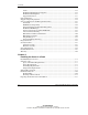
Contents About This Guide Audience Assumptions...................................................................................................... xi Important Safety Information ............................................................................................ xi Symbols on Equipment ..................................................................................................... xi Rack Stability .............................................................................................
Contents Video .......................................................................................................................1-12 Redundant Hot-Plug Power Supplies ......................................................................1-12 Redundant Hot-Plug Fans .......................................................................................1-13 Supported Interfaces................................................................................................1-13 Optional Features.........
Contents Measuring with the Rack Template ........................................................................ 2-13 Installing the Rack Rail Assemblies ....................................................................... 2-16 Preparing the Server for Rack Installation .................................................................... 2-18 Attaching the Server Rails ...................................................................................... 2-19 Lightening the Chassis....................
Contents Hot-Replacing Memory...........................................................................................5-13 Hot-Adding Memory...............................................................................................5-15 Hot-Upgrading Memory..........................................................................................5-18 Non-RAID Memory Support...................................................................................5-21 Mass Storage ..............................
Contents Server Power............................................................................................................. 7-7 Power-On Self-Test (POST) ................................................................................... 7-10 Powering Down the Server............................................................................................ 7-13 Chapter 8 Configuring the Server Setting Up the Base Environment .........................................................................
Contents Appendix A Regulatory Compliance Notices Regulatory Compliance Identification Numbers ............................................................ A-1 Federal Communications Commission Notice ............................................................... A-2 Modifications ........................................................................................................... A-2 Mouse Compliance Statement..................................................................................
Contents PCI Hot Plug LED Indicators ................................................................................ D-12 Memory Cartridge LED Indicators ........................................................................ D-15 DIMM Status LED Indicators................................................................................ D-16 Switches........................................................................................................................
About This Guide This guide provides step-by-step instructions for installation, and reference information for operation, troubleshooting, and future upgrades for the ProLiant DL740 server. Audience Assumptions This guide is for the person who installs, administers, and troubleshoots servers. HP assumes you are qualified in the servicing of computer equipment and trained in recognizing hazards in products with hazardous energy levels.
About This Guide This symbol indicates the presence of hazardous energy circuits or electric shock hazards. Refer all servicing to qualified personnel. WARNING: To reduce the risk of injury from electric shock hazards, do not open this enclosure. Refer all maintenance, upgrades, and servicing to qualified personnel. This symbol indicates the presence of electric shock hazards. The area contains no user or field serviceable parts. Do not open for any reason.
About This Guide Rack Stability WARNING: To reduce the risk of personal injury or damage to the equipment, be sure that: • The leveling jacks are extended to the floor. • The full weight of the rack rests on the leveling jacks. • The stabilizing feet are attached to the rack if it is a single-rack installation. • The racks are coupled together in multiple-rack installations. • Only one component is extended at a time.
About This Guide Server Labels A significant amount of server configuration and options installation information is provided on the server labels. As shown in Figure 1, these labels are located on the top of the unit and inside the unit. NOTE: These labels do not contain warning and caution information. Refer to this guide or to the option documentation for the applicable warnings and cautions.
About This Guide Related Documents For additional information on the topics covered in this guide, refer to the following documentation: • Rack Resource Kits are included with the racks and include the following (depending on rack model): — Rack Products Documentation CD—Available on the HP website or included with the Rack Resource Kit. — 10000 Series Rack Resource Kit—Included with all HP 10000 Series racks.
About This Guide Getting Help If you have a problem and have exhausted the information in this guide, you can get further information and other help in the following locations. Technical Support In North America, call the HP Technical Support Phone Center at 1-800-652-6672. This service is available 24 hours a day, 7 days a week. For continuous quality improvement, calls may be recorded or monitored. Outside North America, call the nearest HP Technical Support Phone Center.
About This Guide Authorized Reseller For the name of your nearest authorized reseller: • In the United States, call 1-800-345-1518. • In Canada, call 1-800-263-5868. • Elsewhere, see the HP website for locations and telephone numbers. Optional Installation Service You may choose to have HP install your system. The installation service can be purchased as a Care Pack packaged service or as a customized service agreement to meet your specific requirements.
About This Guide Reader’s Comments HP welcomes your comments on this guide. Please send your comments and suggestions by e-mail to ServerDocumentation@hp.com. xviii HP ProLiant DL740 Server User Guide HP CONFIDENTIAL Writer: Anna Roberts File Name: a-frnt.
1 Server Features ProLiant DL740 Servers The ProLiant DL740 server, a high-density enterprise-class and datacenter server, delivers 8-way scalable performance for 24 x 7 multiserver rack environments. The ProLiant DL740 server, which is based on F8 architecture, delivers this performance through Intel® Xeon processor MP technology, scalable performance of I/O and memory, and high levels of fault tolerance and manageability for the data center.
Server Features In addition to Hot Plug RAID Memory, other high-availability features include: • Redundant array of memory with error checking and correcting (ECC) and multibit error (MBE) correction • Fault-tolerant integrated Processor Power Modules (PPM) • PCI Hot Plug slots • Redundant hot-pluggable power supplies • Redundant hot-pluggable fans • Redundant NIC support • Smart Array 5i Controller • Disk drive fault tolerance • Automatic Server Recovery (ASR-2) • Dual power cords Serv
Server Features In ProLiant DL740 servers, you can access options and accessories easily through a top access panel and two removable modules: The host module and the power and media module. Refer to Figure 1-1, Figure 1-2, and Figure 1-3 for identification of these modules and other components.
Server Features Figure 1-2: Server front view—module components Item 1-4 Description 1 Power supply 1 2 Hot-plug hard drives 3 Universal media bay 4 Power supply 2 HP ProLiant DL740 Server User Guide HP CONFIDENTIAL Writer: Anna Roberts File Name: b-ch1 Server Features.
Server Features Figure 1-3: Server rear view—module components Item Description 1 System fans 2 AC power ports 3 I/O expansion slots 4 External connectors HP ProLiant DL740 Server User Guide HP CONFIDENTIAL Writer: Anna Roberts File Name: b-ch1 Server Features.
Server Features Standard Features The following additional features are available on ProLiant DL740 models.
Server Features Hot Plug RAID Memory The HP memory RAID technology stands for Redundant Array of Industry-Standard DIMMs. The ProLiant DL740 server supports up to 40 GB of Hot Plug RAID Memory using industry-standard PC133 SDRAM DIMMs (32 GB of addressable memory). The DIMMs are installed in five Hot Plug RAID Memory cartridges. Hot Plug RAID Memory allows for the following server service and management capabilities while the server is running: • Memory hot-replace—Allows the replacement of failed DIMMs.
Server Features The Hot Plug RAID Memory cartridges are located on the inner right side of the host module. Each memory cartridge contains up to eight DIMMs. Each cartridge has a protective cover, and a latch and lock. Figure 1-4: Memory cartridge location 1-8 HP ProLiant DL740 Server User Guide HP CONFIDENTIAL Writer: Anna Roberts File Name: b-ch1 Server Features.
Server Features The ProLiant DL740 server has five memory cartridges, each consisting of eight DIMMs. In each memory cartridge, similar DIMMs are installed in bank pairs (1+2, 3+4, 5+6, 7+8) for memory interleaving to increase performance.
Server Features PCI-X Technology PCI-X technology leverages the wide acceptance of the PCI bus and provides an evolutionary I/O upgrade to conventional PCI. PCI-X technology enhances the PCI protocol and frequency to meet bandwidth needs of enterprise computing systems. PCI-X provides backward compatibility with the PCI bus at both the expansion board and system level.
Server Features Network Interface Controllers The ProLiant DL740 server is equipped with two embedded Gigabit Ethernet network interface controllers. Each of these 10/100/1000 Base TX UTP 100-MHz 64-bit PCI-X NICs have the following features: • Two RJ-45 connectors for 10BaseT, 100BaseTX, or 1000BaseTX Ethernet • Preboot eXecution Environment (PXE) support Redundant NIC software, located on the SmartStart CD, supports a redundant NIC configuration.
Server Features Internal Hot-Plug Drive Bays The internal hot-plug drive bays support four one-inch Ultra3 SCSI hard drives. Drives may be of any storage capacity but must be mounted on HP universal drive carriers (hot-plug drive trays). Universal Media Bay The universal media bay supports hot-pluggable IDE devices and ships standard with a DVD-ROM drive. The bay also supports other removable media devices, such as a CD-ROM drive.
Server Features Redundant Hot-Plug Fans ProLiant DL740 servers include 1 + 1 redundant hot-plug fans. If a fan fails, the server generates a system alert and triggers the redundant fan to take over automatically. The redundant hot-plug system fans protect the various server components from overheating and possibly causing a system interruption. Diagnostic LEDs exist near each fan and on the front of the server. For more information on the hot-plug fan LEDs, refer to Appendix D.
Server Features Optional Features The ProLiant DL740 server supports a wide range of server hardware options. HP server options are available from an HP authorized reseller or HP authorized service provider. Additional information about HP servers and options can be found in the QuickSpecs on the HP website.
Server Features Server Configuration and Management Features HP offers an extensive set of features and tools to support effective server configuration and management, including: • SmartStart • RBSU • iLO Standard Management • Redundant ROM images • Advanced data guarding (RAID ADG) • HP utilities for Microsoft Windows • HP utilities for Linux • Insight Manager 7 • Integrated Management Log (IML) SmartStart SmartStart, which is located on the SmartStart CD, allows you to configure your HP
Server Features ROM-Based Setup Utility RBSU automatically configures the system based on the selected operating system.
Server Features Integrated Lights-Out Standard Management Integrated Lights-Out (iLO) is an HP engineered application-specific integrated circuit (ASIC) that embodies industry-leading Lights, -Out management functionality on the ProLiant DL740 server. Features iLO Standard includes basic system board management functions, diagnostics, and essential Lights-Out functionality. iLO Standard is provided as standard on all ProLiant DL740 servers.
Server Features • Alert forwarding and administration • Remote firmware update • SSL security iLO Advanced Features (Optional) The iLO Advanced option provides: • Virtual floppy drive • Virtual graphical console • Virtual CD • Directory services (future support) • PKI support (future support) IMPORTANT: To use the iLO Advanced Features, you must purchase a license key for the Integrated Lights-Out Advanced Pack. For more information on the Integrated Lights-Out Advanced Pack, refer to www.
Server Features Smart Components for Online ROM Flash Online ROM flash technology consists of a combination of components that allow system administrators to upgrade system or option ROM images across a wide range of HP servers and server options while the server is running. The ROM upgrades are performed locally or across a network from a single point of execution and are flashed individually or grouped together to perform multiple ROM upgrades in a single step.
Server Features Only the Smart Array 5300 Controllers support RAID ADG. The Smart Array 5304/128 is shipped with RAID ADG and is available as an upgrade option for the Smart Array 5302/32 and 5302/64. For more information about RAID ADG, refer to the storage controller documentation at: www.compaq.com/products/servers/proliantstorage/arraycontrollers/ docs/index.
Server Features HP has an array of Opensource projects for Linux. For more information on HP Opensource projects refer to: opensource.hp.com/ HP only supports servers configured with certified Linux operating system versions found on the Linux server certification matrix website: h18000.www1.hp.com/products/servers/linux/hplinuxcert.html Insight Manager 7 Insight Manager 7 is a systems management tool that provides performance, configuration, and fault management for HP servers and clients.
Server Features Integrated Management Log The Integrated Management Log (IML) records all system events and stores them in an easily viewable form. These events are recorded and marked with a time stamp. For more information about the IML, refer to the “Integrated Management Log” section in Chapter 9.
Server Features Security Features The following sections outline the security features available for the ProLiant DL740 server. Software Security The following software security features are established through RBSU: • Administrator password—Prevents changes to the configuration unless you enter the password. • Diskette drive control—Enables and disables the diskette drive. When disabled, the diskette drive will not read, write, or boot.
Server Features Hardware Security The ProLiant DL740 server has a switch on the I/O board that establishes the following hardware security features: • Configuration (NVRAM) lock—Disallows configuration changes when enabled by preventing nonvolatile memory from being modified. • Diskette boot control—Enables and disables the diskette boot functions. When disabled, the system will not boot from a diskette, but runtime diskette read and write functions are still available.
Server Features Routine Maintenance For information about routine maintenance and safety precautions, refer to the server documentation CD included with your server. HP ProLiant DL740 Server User Guide HP CONFIDENTIAL Writer: Anna Roberts File Name: b-ch1 Server Features.
Server Features Warranty Warranty features include: • Three-Year Parts, Labor, and On-Site Limited Warranty with next business day response • Pre-Failure Warranty on processors, memory, and hard drives (requires installation of Insight Manager 7) For additional service and support offerings, visit the HP website: www.hp.com 1-26 HP ProLiant DL740 Server User Guide HP CONFIDENTIAL Writer: Anna Roberts File Name: b-ch1 Server Features.
2 Installing the Server in a Rack This chapter specifies the procedures required to install a ProLiant DL740 server in an HP or industry-standard 19-inch rack. Figure 2-1: ProLiant DL740 server HP ProLiant DL740 Server User Guide HP CONFIDENTIAL Writer: Anna Roberts File Name: c-ch2 Installing the Server in a Rack.
Installing the Server in a Rack Rack Installation Overview Installing the ProLiant DL740 server in a rack requires the following steps (detailed later in this chapter): 1. Select a site and unpack the server. Refer to the “Selecting a Site” and “Shipping Box Contents” sections in this chapter. 2. Remove the host module and power and media module to lighten the chassis. Refer to the hood labels and to Chapter 3 for host module and media and power module removal instructions. 3.
Installing the Server in a Rack Selecting a Site When installing the ProLiant DL740 server in a rack, the following standards must be met: • Space and airflow requirements • Power requirements • Grounding requirements • Temperature requirements Space and Airflow Requirements To allow for servicing and adequate airflow, observe the following spatial requirements when deciding where to install a rack: • Leave a minimum clearance of 63.5 cm (25 inches) in front of the rack.
Installing the Server in a Rack CAUTION: Always use blanking panels to fill empty vertical spaces in the rack. This arrangement ensures proper airflow. Using a rack without blanking panels results in improper cooling that can lead to thermal damage. Compaq branded 9000 and 10000 Series racks provide proper server cooling from flow-through perforations in the front and rear doors that provide 64 percent open area for ventilation.
Installing the Server in a Rack Power Requirements WARNING: To reduce the risk of personal injury, fire, or damage to the equipment, do not overload the AC supply branch circuit that provides power to the rack. Consult the electrical authority having jurisdiction over your facility wiring and installation requirements.
Installing the Server in a Rack Power Supplies The following requirements apply to power supplies: • The ProLiant DL740 server has two hot-plug, redundant power supplies. Depending on the system load configuration and input voltage (110 or 220), more than one power supply may be required to power the system. • Power supplies are load balancing. • Power supplies must be run at highline (200−240 VAC) for redundancy.
Installing the Server in a Rack Grounding Requirements WARNING: To reduce the risk of electrical shock from high leakage currents, a reliable, grounded (earthed) connection is essential before connecting the unit to an AC supply. For proper operation and safety, this equipment is required to be correctly grounded. In the United States, install the equipment in accordance with ANSI/NFPA 70, 1999, Article 250, and with any local and regional building codes.
Installing the Server in a Rack Temperature Requirements To be sure of continued safe and reliable operation of the equipment, install the system in a well-ventilated, climate-controlled environment. The HP Maximum Recommended Ambient Operating Temperature (TMRA) for most server products is 35° C (95° F). The temperature in the room where the rack is located should not exceed 35° C (95° F).
Installing the Server in a Rack Shipping Box Contents Unpack the shipping boxes by following the instructions and illustrations printed on the outsides of the boxes.
Installing the Server in a Rack Rack Considerations Consider the following issues when working with server rack systems. Rack Stability Rack stability is of special concern when equipment is routinely installed, removed, or accessed within the rack. Stability is achieved through the use of leveling feet (jacks), stabilizers, and ballast kits. Leveling Feet (Jacks) Leveling feet are adjustable stabilizers that level the cabinet at the installation site and take the balance off of the wheels.
Installing the Server in a Rack A single ProLiant DL740 server typically weighs between 48 and 61 kg (105 and 135 lbs), depending on configuration. If a single ProLiant DL740 server is the only component installed in a rack, you must add two ballast kits. Each kit contains two 18 kg (40 lb) ballasts. Two ballast kits (a total of four ballasts) equal 73 kg (160 lb), bringing the total up to a minimum of 136 kg (300 lb).
Installing the Server in a Rack WARNING: To reduce the risk of personal injury or damage to the equipment, be sure that: • The leveling jacks are extended to the floor. • The full rack weight rests on the leveling jacks. • The stabilizing feet are attached to the rack if it is a single rack installation. • The racks are coupled together in multiple rack installations. • A rack may become unstable if more than one component is extended for any reason. Extend only one component at a time.
Installing the Server in a Rack Preparing the Rack for Server Installation To prepare the rack for a server installation: • Measure with the rack template • Install the rack rail assemblies Measuring with the Rack Template The rack template provides an easy and reliable way to properly position the rack rail assemblies in the rack. • The template is two-sided and is printed with arrows that show you where to insert rack rail assemblies on the front and back of the rack.
Installing the Server in a Rack To identify the required space and location for the server with the template: 1. Identify the front side of the template. 2. Starting at the bottom of the rack, or at the top of a previously mounted component, secure the template against the front of the rack by pressing the two push tabs. Match the hole pattern on the template with the holes on the vertical rails of the rack. Figure 2-2: Measuring with the template 3.
Installing the Server in a Rack 4. Using a pencil, mark the locations on the rack where you insert the rack rail tabs. 5. On the rack, mark the top and bottom edges of the template . This step helps you align a template for the next component. 6. Move to the rear of the rack and turn the template over so you can use the backside of the template. 7. Repeat steps 2 through 5 with the back of the template on the rear of the rack.
Installing the Server in a Rack Installing the Rack Rail Assemblies To install the rack rail assemblies in the rack: 1. From the front of the rack, identify the rear rack holes on the inside of the vertical rack that you marked with the template. 2. Pull the rail compression lever toward you. Figure 2-3: Pulling the rail compression lever 2-16 HP ProLiant DL740 Server User Guide HP CONFIDENTIAL Writer: Anna Roberts File Name: c-ch2 Installing the Server in a Rack.
Installing the Server in a Rack 3. Insert the two rail tabs from the end of the rack rail assembly into the marked holes on the inside of the rear of the rack. Figure 2-4: Inserting the rail tabs on the rear of the rack 4. Adjust the rack rail depth by sliding it forward. HP ProLiant DL740 Server User Guide HP CONFIDENTIAL Writer: Anna Roberts File Name: c-ch2 Installing the Server in a Rack.
Installing the Server in a Rack 5. Insert the two rail tabs from the rack rail assembly into the marked holes on the inside of the front of the rack. Figure 2-5: Inserting the rail tabs on the front of the rack 6. Release the rail compression lever to seat the tabs in the rack post. 7. Repeat steps 1 through 6 for the other rail.
Installing the Server in a Rack Attaching the Server Rails To attach the server rails to the ProLiant DL740 server chassis: IMPORTANT: Install the server rails with the smooth side of the rail against the server chassis. 1. Align the four keyholes on one of the server rails above the four spools on the side of the chassis. 2. Press the rail against the side of the chassis and slide the rail toward the front of the server to snap and lock the rail into place.
Installing the Server in a Rack Lightening the Chassis To make moving and lifting the server more manageable, HP recommends removing the server modules to lighten the chassis. WARNING: Each server module weighs more than 16 kg (35 lb). Before removing the server modules, remove the processor boards and power supplies to lighten the modules before handling, or have at least two people handle the modules together. 1. Remove the host module as shown in the “Removing the Host Module” section of Chapter 3. 2.
Installing the Server in a Rack Installing the Server in the Rack To complete the server rack installation, load the server onto the rack rails and reinstall the server modules. Loading the Server onto the Rack Rails WARNING: To avoid destabilizing the rack, install servers starting from the bottom of the rack. To install the server in the rack: 1. Pull the inner slide rail forward from each rack rail assembly until it locks into place (1). 2. Slide the inner bearing brace forward until it stops (2).
Installing the Server in a Rack 3. Use two people to lift the server by its four lift handles (1) and carefully align the open ends of the server rails on the rear of the server with the extended bearing brace and inner slide rail of the rack rail assemblies (2). 4. Insert the server rails into the extended inner slide rails on both sides, and then slowly slide the server into the rack. Continue sliding the server backward until the rail-release levers engage the rack rail assemblies (3).
Installing the Server in a Rack 5. Reach around the front of the server to press the rail-release levers at the front of both server rails, and continue to slide the server into the rack. Figure 2-9: Sliding the server to the rear of the rack 6. After the server reaches the rear of the rack, slide it back out of the rack until the rack assembly is fully extended and the rails lock. This action initializes the rail lock for future use. 7.
Installing the Server in a Rack 8. Tighten the thumbscrews to secure the server to the rack. Figure 2-10: Tightening the thumbscrews Rack Template The HP ProLiant DL740 server rack template has procedures detailing the rack installation of the ProLiant DL740 server and how to install the cable management hardware. 2-24 HP ProLiant DL740 Server User Guide HP CONFIDENTIAL Writer: Anna Roberts File Name: c-ch2 Installing the Server in a Rack.
3 Server Access The ProLiant DL740 server provides easy access to all internal components for installation and maintenance. This chapter provides details concerning system power and power supply indicators and removal of the server modules. HP ProLiant DL740 Server User Guide HP CONFIDENTIAL Writer: Anna Roberts File Name: d-ch3 Server Access.
Server Access Server Access Overview The ProLiant DL740 server chassis facilitates the installation of hardware upgrades through the use of two removable modules and top access panels. The following table describes the contents of the modules and how to access the components. Table 3-1: Module and Bay Components and Access Module Contents Access Method PCI Hot Plug expansion slots Open the top access panels. Configuration switches Open the top access panels. Fans 1 and 2 Open the top access panels.
Server Access Unit Identification Switches (Front and Rear) The ProLiant DL740 server offers Unit Identification (UID) LED switches to aid in identifying specific servers in a rack environment. Each ProLiant DL740 server has two unit identification switches, one on the front of the server and one on the back of the server. When activated from either the front or rear of the server, both Unit Identification switches illuminate.
Server Access Accessing the Host Module To access the host module to install or replace hot-plug fans or PCI Hot Plug boards: 1. Slide the chassis out of the rack. 2. Unlock the top latch security screw and raise the latch (1), as shown in Figure 3-2. Hold down the top right access panel and lift the top left access panel (2). Then lift the top right access panel (3).
Server Access Removing the Host Module Use the procedure in the preceding section, “Accessing the Host Module,” to install or replace hot-plug fans or PCI/PCI-X Hot Plug expansion boards. To replace or service non-hot-plug components or address problems in the host module, remove the module from the chassis. WARNING: The host module weighs more than 16 kg (35 lb). Remove both processor boards or all of the memory cartridges before handling the module, or have at least two people handle the module together.
Server Access 5. Push the processor board lever latch down to release the lever (1). 6. Lift the processor board lever up (2) to release the board, and lift the processor board out of the module (3). Figure 3-3: Removing the processor board 3-6 HP ProLiant DL740 Server User Guide HP CONFIDENTIAL Writer: Anna Roberts File Name: d-ch3 Server Access.
Server Access 7. Push in on the sides of the module release levers (1) on the host module and rotate the top of the levers downward (2), as shown in Figure 3-4. 8. Pull the host module out of the chassis (3). Figure 3-4: Releasing the host module 9. Set the host module aside for servicing non-hot-plug components. WARNING: To reduce the risk of personal injury from hot surfaces, allow the internal system components to cool before touching them. 10.
Server Access 11. To reassemble the server, slide the module into the chassis until the module release levers begin to rotate. Then push the levers shut until they snap into place. 12. Reinstall the cable management harness and I/O cables in the reverse order from the steps used to remove them. Host Module Components Refer to Table 3-2 to identify components in the host module.
Server Access The system board is located in the bottom of the host module. Refer to Table 3-3 to identify components on the system board. Figure 3-6: System board components HP ProLiant DL740 Server User Guide HP CONFIDENTIAL Writer: Anna Roberts File Name: d-ch3 Server Access.
Server Access Table 3-3: System Board Components 3-10 Item Component 1 Fan 2 connector 2 Fan 1 connector 3 Memory cartridge 1 connector 4 Memory cartridge 2 connector 5 Memory cartridge 3 connector 6 Memory cartridge 4 connector 7 Memory cartridge 5 connector 8 Processor board 2 connector 9 Processor board 1 connector 10 Remote Insight board connector 11 System/midplane board connector 12 I/O board connector 13 System battery 14 iLO diagnostic LEDs HP ProLiant DL740 Server U
Server Access Removing the Power and Media Module WARNING: The power and media module weighs more than 16 kg (35 lbs) HP recommends removing both power supplies before handling the module, or having two people handle the module together. CAUTION: Do not attempt to remove the power and media module while power is applied to the system. The module is not hot-pluggable. Immediate system shutdown and data loss will occur. To remove the power and media module: 1.
Server Access 4. Press the power supply latch to release the power supply handle (1). 5. Rotate the power supply handle outward (2) and slide the power supply out of the chassis (3), as shown in Figure 3-7. Use both hands when removing the power supply to support its weight. The power supplies weigh 4 kg (9 lbs) each. NOTE: When you remove the power supply, a spring-loaded trap door closes to block the opening. This door preserves the air path required to cool the internal components of the server.
Server Access 6. Open the top access panels as shown in Figure 3-2 7. Slide the module release levers (1) on the power and media module, as shown in Figure 3-8. 8. Pull the power and media module (2) out of the chassis until it encounters the module stop latches. Figure 3-8: Releasing the power and media module HP ProLiant DL740 Server User Guide HP CONFIDENTIAL Writer: Anna Roberts File Name: d-ch3 Server Access.
Server Access 9. Press in on the module stop latches (1) and pull the module out of the chassis (2), as shown in Figure 3-9. Figure 3-9: Removing the power and media module WARNING: To reduce the risk of personal injury from hot surfaces, allow the internal system components to cool before touching them. 10. To reassemble the server, slide the module into the chassis until the levers snap into place.
Server Access Power and Media Module Components Refer to Table 3-4 to identify components in the power and media module. Figure 3-10: Power and media module components Table 3-4: Power and Media Module Components Item Component Item Component 1 Ultra3 hard drive SCSI ID 0 7 Universal media bay, with DVD/CD-ROM drive 2 Ultra3 hard drive SCSI ID 1 8 1.
4 Installing Hardware Options, Non-Hot-Plug The following instructions are provided as an overview for installing hardware option upgrades that require the system power to be off. HP recommends that you use the documentation provided with the hardware option for complete installation instructions. You can also refer to the HP ProLiant DL740 Server Supplemental Setup Guide included in the shipping box or to the labels attached to the top panel of the server.
Installing Hardware Options, Non-Hot-Plug Intel Xeon Processor MP The ProLiant DL740 server supports either four or eight processors. 4-2 • All processors installed on a processor board must be the same speed, cache size, and stepping. Stepping refers to the processor revision. • If two processor boards are installed, all processors in both processor boards must be the same speed, cache size, and stepping. • Processor 1 must always be installed to properly terminate the processor bus.
Installing Hardware Options, Non-Hot-Plug Figure 4-1: Processor board layout Item Description 1 Intel Xeon processor MP in socket 1 2 Intel Xeon processor MP in socket 2 3 Intel Xeon processor MP in socket 3 4 Intel Xeon processor MP in socket 4 HP ProLiant DL740 Server User Guide HP CONFIDENTIAL Writer: Anna Roberts File Name: e-ch4 Install Hardware Options Non Hot-Plug.
Installing Hardware Options, Non-Hot-Plug Installing a Processor Board The ProLiant DL740 server is capable of supporting up to eight Intel Xeon processors MP and is shipped with four processors installed. The ProLiant DL740 server has space for two processor boards in the host module.
Installing Hardware Options, Non-Hot-Plug To install a processor board option kit (with four processors) into the host module: 1. Back up all data on the server. 2. Shut down the operating system as directed by your operating system instructions. 3. If the server was not powered down in the previous step, power down the server (refer to Chapter 7). 4. Disconnect the power cords from the server. 5. Open the top access panels to access the host module (refer to Chapter 3).
Installing Hardware Options, Non-Hot-Plug 7. Insert the processor board into processor board slot 2 of the module (1). 8. Push down the processor board lever until it is secured by the lever latch (2). Figure 4-4: Installing the processor board 9. Close the top access panels. NOTE: Processor board 2 need not be installed for the server to run. If only one processor board is installed, be sure the processor board air baffle is in place to provide optimal airflow. 10.
Installing Hardware Options, Non-Hot-Plug Non-Hot-Plug I/O Expansion The PCI-X slots of the ProLiant DL740 server I/O board support a variety of industry-standard expansion boards. WARNING: To reduce the risk of personal injury from hazardous energy or damage to the equipment when working on energized servers: • Remove all watches, rings, and any other loose-fitting jewelry. • Avoid the use of conductive tools that could bridge live parts.
Installing Hardware Options, Non-Hot-Plug Table 4-1: I/O Expansion Slots Item Description Slots 1–2 PCI bus 7—Supports 64-bit PCI-X expansion boards at 100 MHz; it is keyed for 3.3v signaling. Slots 3–4 PCI bus 11—Supports 64-bit PCI-X expansion boards at 100 MHz; it is keyed for 3.3v signaling. Slots 5–6 PCI bus 3—Supports 64-bit PCI-X expansion boards at 100 MHz; it is keyed for 3.3v signaling.
Installing Hardware Options, Non-Hot-Plug To add an expansion board: 1. Press on the top (1) of the appropriate expansion slot release lever and open the lever toward the rear (2) of the expansion slot. 2. Remove the expansion slot cover (3). Figure 4-6: Preparing the expansion slot for installation HP ProLiant DL740 Server User Guide HP CONFIDENTIAL Writer: Anna Roberts File Name: e-ch4 Install Hardware Options Non Hot-Plug.
Installing Hardware Options, Non-Hot-Plug 3. Insert the PCI/PCI-X expansion board into the appropriate expansion slot (1), pushing firmly until the board is securely seated. 4. Close the expansion slot release lever from the rear of the unit to secure the board (2). Be sure that the lever latches into the closed position. Figure 4-7: Inserting the PCI/PCI-X expansion board 5. Connect the expansion board I/O cable as appropriate.
Installing Hardware Options, Non-Hot-Plug HP has designed a self-latching slot-keeper feature to accommodate full-length expansion boards. Be sure that the V-shaped slot-keeper tabs on the plastic expansion board guide are positioned over the forward end of the expansion board. Using the slot keepers is especially important when expansion boards are added or when the server is moved. Figure 4-8: Full-length self-latching slot-keeper feature 6.
Installing Hardware Options, Non-Hot-Plug Installing the Integrated Array Bypass Use the Integrated Array Bypass kit to bypass the Smart Array 5i Controller and use an optional controller. The Smart Array 5i Controller is routed to the internal drives through the Array Enabler board in the host module. The Integrated Array Bypass kit allows you to replace the Array Enabler board with a connector and cable that you can connect to an optional controller board.
Installing Hardware Options, Non-Hot-Plug 6. Open the top left access panel, as shown in Chapter 3. 7. Slide the retaining clip (1) and remove the Array Enabler board (2) from the server, as shown in Figure 4-9. NOTE: Retain the Array Enabler board for future use. Figure 4-9: Removing the Array Enabler board HP ProLiant DL740 Server User Guide HP CONFIDENTIAL Writer: Anna Roberts File Name: e-ch4 Install Hardware Options Non Hot-Plug.
Installing Hardware Options, Non-Hot-Plug 8. Install the Integrated Array Bypass assembly, as shown in Figure 4-10. IMPORTANT: The Integrated Array Bypass assembly cable comes as a standard accessory in the hardware option kit. Figure 4-10: Installing the Integrated Array Bypass assembly 4-14 HP ProLiant DL740 Server User Guide HP CONFIDENTIAL Writer: Anna Roberts File Name: e-ch4 Install Hardware Options Non Hot-Plug.
Installing Hardware Options, Non-Hot-Plug 9. Press on the top (1) of the appropriate expansion slot release lever and open the lever toward the rear (2) of the expansion slot. 10. Remove the expansion slot cover (3). Figure 4-11: Preparing the expansion slot for installation HP ProLiant DL740 Server User Guide HP CONFIDENTIAL Writer: Anna Roberts File Name: e-ch4 Install Hardware Options Non Hot-Plug.
Installing Hardware Options, Non-Hot-Plug 11. Install the optional array controller board (1) as shown in Figure 4-12 and close the expansion slot release lever (2). Close the full-length self-latching slot-keeper feature. IMPORTANT: HP recommends installing the optional array controller board into PCI-X slot 6. Figure 4-12: Installing the array controller board 4-16 HP ProLiant DL740 Server User Guide HP CONFIDENTIAL Writer: Anna Roberts File Name: e-ch4 Install Hardware Options Non Hot-Plug.
Installing Hardware Options, Non-Hot-Plug 12. Connect the Integrated Array Bypass assembly cable to the optional array controller board, as shown in Figure 4-13. Figure 4-13: Connecting the Integrated Array Bypass assembly cable NOTE: The actual appearance and routing of the cable in the preceding figures depend on which slot the optional array controller board occupies. 13. Close the top left access panel and slide the server into the rack. 14.
5 Installing Hardware Options, Hot-Plug The following instructions are provided as an overview for installing hardware option upgrades that are hot-pluggable. HP recommends that you use the documentation provided with the hardware option for complete installation instructions. You can also refer to the HP ProLiant DL740 Server Supplemental Setup Guide included in the shipping box or to the labels attached to the top panel of the server.
Installing Hardware Options, Hot-Plug Hot Plug RAID Memory The ProLiant DL740 server supports up to 40 GB of Hot Plug RAID Memory using industry-standard PC133 SDRAM DIMMs (32GB of addressable memory). The DIMMs are installed in the five Hot Plug RAID Memory cartridges. The following sections describe the features and operation of the Hot Plug RAID Memory cartridges. Memory Cartridge Overview The Hot Plug RAID Memory cartridges are located in the right side of the host module.
Installing Hardware Options, Hot-Plug Memory Cartridge Components The following figure and table show the various components of the memory cartridges. Figure 5-2: Memory cartridge components Item Description 1 Cartridge lever 2 Cartridge lock 3 Cartridge attention LED 4 Cartridge power LED Memory Cartridge Guidelines The ProLiant DL740 Server has five Hot Plug RAID Memory cartridges. They are designed to allow the removal of a single cartridge while the server is running.
Installing Hardware Options, Hot-Plug The ProLiant DL740 server has eight memory banks, each consisting of five DIMMs installed across the five memory cartridges. Similar DIMMs are installed in bank pairs (1+2, 3+4, 5+6, 7+8) for memory interleaving to increase performance. NOTE: For more information, refer to the memory cartridge covers or DIMM installation guidelines later in this chapter.
Installing Hardware Options, Hot-Plug Memory Cartridge LED Indicators The ProLiant DL740 server has LEDs for each of the memory cartridges. These LEDs are used to determine the status of memory installed in the server.
Installing Hardware Options, Hot-Plug Each memory cartridge has two LEDs located on it. The memory cartridge LEDs are used to determine the power status of the memory cartridge and whether or not it requires maintenance attention. Figure 5-4: Memory cartridge LEDs Item 5-6 Description 1 Cartridge attention LED 2 Cartridge power LED HP ProLiant DL740 Server User Guide HP CONFIDENTIAL Writer: Anna Roberts File Name: f-ch5 Installing Hardware Options Hot-Plug.
Installing Hardware Options, Hot-Plug LED Indicator State Definitions Table 5-2 provides descriptions of the various LED states. Table 5-2: Memory Cartridge LED State Definitions LED Indicator Cartridge Power LED (green) Cartridge Attention LED (amber) DIMM Status LED (amber) State Condition Action Solid Cartridge online (normal) None Off Cartridge not online Lock cartridge or check other LEDs. Blinking Cartridge rebuild and verify in progress Wait until LED stops blinking.
Installing Hardware Options, Hot-Plug Accessing the DIMMs To access the DIMMs in the server, you must remove the memory cartridge. The Hot Plug RAID Memory cartridge is designed to allow you to replace, add, or upgrade memory while the system is online. Removing the Memory Cartridge To remove a memory cartridge from the ProLiant DL740 server: 1. Slide the server out of the rack and open the top access panels. 2. Unlock the memory cartridge by sliding the cartridge lock (1) open.
Installing Hardware Options, Hot-Plug Figure 5-5: Removing the memory cartridge DIMM Overview The ProLiant DL740 server has five memory cartridges, each consisting of eight DIMMs. The server supports up to 40 GB of Hot Plug RAID Memory using industrystandard PC133 SDRAM DIMMs (32 GB of addressable memory). Locating the DIMM Sockets Figure 5-6 and Table 5-3 detail the DIMM socket locations on the memory cartridge.
Installing Hardware Options, Hot-Plug Figure 5-6: DIMM socket location Table 5-3: DIMM Socket Location Item 5-10 Description Bank 1 DIMM socket 1 DIMM bank 1 2 DIMM socket 2 DIMM bank 2 3 DIMM socket 3 DIMM bank 3 4 DIMM socket 4 DIMM bank 4 5 DIMM socket 5 DIMM bank 5 6 DIMM socket 6 DIMM bank 6 7 DIMM socket 7 DIMM bank 7 8 DIMM socket 8 DIMM bank 8 Bank pair for interleaving Bank pair for interleaving Bank pair for interleaving Bank pair for interleaving HP ProLiant DL740 Se
Installing Hardware Options, Hot-Plug Installing DIMMs in the Memory Cartridge CAUTION: When handling a DIMM, be careful not to touch any of the contacts. Doing so may damage the DIMM. IMPORTANT: Be sure that DIMMs are installed in the proper orientation. The DIMMs are keyed to ensure they are installed correctly in the memory socket. Refer to your system documentation for details.
Installing Hardware Options, Hot-Plug 3. Be sure that all of the DIMM socket levers are rotated inward. 4. Insert the memory cartridge into the server with the cartridge lock in the unlocked position, and secure the cartridge in place by rotating the cartridge lever down. 5. Lock the memory cartridge by sliding the cartridge lock to the closed position. 6. Be sure that the cartridge is online (cartridge power LED solid).
Installing Hardware Options, Hot-Plug Hot-Replacing Memory If there is a problem with a DIMM in the server, the DIMM status LEDs will illuminate as either solid or blinking. If the DIMM status LED for a specific DIMM in a specific cartridge is solid, then the DIMM needs to be replaced. CAUTION: A redundant memory configuration is required when performing Hot Plug RAID Memory functions. • If all five memory cartridges are online and error free, any memory cartridge can be removed.
Installing Hardware Options, Hot-Plug To replace DIMMs: 1. Remove the memory cartridge by following the procedure in the “Removing the Memory Cartridge” section of this chapter. CAUTION: Do not remove a memory cartridge if the cartridge power LED is blinking or is solid green. The system will halt. If the cartridge power LED has not turned off after unlocking the cartridge, then one of the following conditions exists: • Another cartridge is either powered down or removed.
Installing Hardware Options, Hot-Plug Hot-Adding Memory For the hot-add feature to work on the ProLiant DL740 server, the operating system must have driver support. Refer to “Installing HP Drivers and Utilities” in Chapter 8 for details on installing HP software. HP recommends having all DIMMs that will be added available before beginning this procedure. CAUTION: A redundant memory configuration is required when performing Hot Plug RAID Memory functions.
Installing Hardware Options, Hot-Plug To install additional DIMMs in the server, you must add them in bank pairs across all five of the memory cartridges, one cartridge at a time. You must add memory and bring the cartridge back online before taking the next cartridge offline. 1. Begin with memory cartridge 1 and: a. Unlock the cartridge and lift it out of the server by following the procedure in the “Removing the Memory Cartridge” section of this chapter.
Installing Hardware Options, Hot-Plug e. Lock the memory cartridge by sliding the cartridge lock to the closed position. f. The system will rebuild and verify the data on the DIMMs in the memory cartridge while the cartridge power LEDs are blinking. This process is complete when the cartridge power LED is illuminated solid green, indicating that the cartridge is online. Memory cartridge 1 is online but the memory has not been activated.
Installing Hardware Options, Hot-Plug Hot-Upgrading Memory For the hot-upgrade feature to work on the ProLiant DL740 server, the operating system must have driver support. Refer to “Installing HP Drivers and Utilities” in Chapter 8 for details on installing HP software. HP recommends having all DIMMs that will replace existing DIMMs available before beginning this upgrade procedure. An upgrade is replacing smaller size DIMMs with larger size DIMMs.
Installing Hardware Options, Hot-Plug 1. Begin with memory cartridge 1: a. Unlock the cartridge and lift it out of the server by following the procedure in the “Removing the Memory Cartridge” section of this chapter. b. Remove the DIMMs that you want to upgrade. c. Install the new memory in the same sockets from which the DIMMs have been removed in accordance with the following guidelines: — Similar DIMMs must be installed in bank pairs and in bank pair order (1+2, then 3+4, then 5+6, then 7+8).
Installing Hardware Options, Hot-Plug IMPORTANT: The memory cartridge power LED must be illuminated solid before you can unlock the next memory cartridge. 2. Repeat step 1 with memory cartridges 2, 3, 4, and 5. Memory cartridges 2, 3, and 4 will not come online unless their memory configurations match that of cartridge 1. After cartridge 5 is online, the newly added memory can be made available to the operating system.
Installing Hardware Options, Hot-Plug Non-RAID Memory Support Non-RAID memory configuration is now more user-friendly in the ProLiant DL740 Server with SmartStart 6.4 and ROM dated 4/21/03 and higher. CAUTION: Running the system in non-RAID memory configuration leaves the system unprotected from multi-bit errors. IMPORTANT: You cannot perform a hot replace, hot add, or hot upgrade of memory if the system is in a non-redundant memory configuration.
Installing Hardware Options, Hot-Plug Mass Storage The following sections provide an overview for installing hard disk drives. The ProLiant DL740 server supports up to four 1-inch Ultra3 or Ultra320 Single Connector Assembly (SCA) hot-plug hard drives. Ultra320 SCSI hard drives will run at Ultra3 speeds unless you install an optional Ultra320 Array Controller and the Twisted Pair Cable Array Bypass kit included with the system.
Installing Hardware Options, Hot-Plug Hot-Plug SCSI Hard Drive LED Indicators The hot-plug SCSI hard drive LEDs, located on each physical drive, are visible on the front of the server or external storage unit. They provide: (1) Activity, (2) Power/Online, and (3) Fault status for each corresponding drive when configured as part of an array and attached to a powered-on controller. Their behavior may vary depending on the status of other drives in the array.
Installing Hardware Options, Hot-Plug Figure 5-10: SCSI hard drive LEDs 5-24 HP ProLiant DL740 Server User Guide HP CONFIDENTIAL Writer: Anna Roberts File Name: f-ch5 Installing Hardware Options Hot-Plug.
Installing Hardware Options, Hot-Plug Guidelines for Installing Hot-Plug SCSI Hard Drives Follow these guidelines when adding SCSI hard drives: • A maximum of four 1-inch Ultra3 or Ultra320 SCSI drives may be added in the media module. Ultra320 SCSI hard drives will run at Ultra3 speeds unless you install an optional Ultra320 Array Controller and the Twisted Pair Cable Array Bypass kit included with the system. • If only one SCSI hard drive is used, install it in bay 0.
Installing Hardware Options, Hot-Plug Installing a Hot-Plug SCSI Hard Disk Drive CAUTION: Before adding or removing any hot-plug SCSI drives, consult the operating system instructions. Failure to do so could result in loss of data or damage to equipment. To install a hot-plug SCSI hard drive: 1. Remove the blanking panel in an unused drive bay by pushing the sides of the retaining clips inward (1), and then pull the blanking panel outward (2), as shown in Figure 5-11.
Installing Hardware Options, Hot-Plug 3. Insert the new hot-plug drive into the empty drive bay, pushing until the unit is securely seated (1). 4. Secure the hot-plug drive in the drive cage by swinging the ejector lever inward (2), as shown in Figure 5-12. Figure 5-12: Installing a SCSI hard drive Guidelines for Replacing Hot-Plug SCSI Hard Drives You should be able to hot-plug a drive during normal activity.
Installing Hardware Options, Hot-Plug Advanced Data Guarding When a hot-pluggable disk drive is removed, although the system is functionally operational, the disk subsystem may no longer be fault tolerant. Fault tolerance will be lost until the removed drive is subsequently replaced and the rebuild operation is completed. This procedure takes several hours, even if the system is not busy while the rebuild is in progress.
Installing Hardware Options, Hot-Plug • Never turn a disk enclosure off while the initiator or controller is powered on or active. Doing so can cause the initiator or controller to mark the drives as failed. This action can result in permanent data loss. • If a drive is replaced while the system is off, it may be necessary to rebuild the replaced drive. Follow the instructions on the screen or the instructions outlined in the system reference guide.
Installing Hardware Options, Hot-Plug Removing the DVD/CD-ROM Drive The universal media bay supports hot-pluggable IDE devices and ships standard with a DVD-ROM drive. The bay also supports other removable media devices, such as a CD-ROM drive. CAUTION: Before removing a drive, be sure to stop the drive using the Windows 2000 Unplug/Eject Hardware applet. Failure to do so will result in a “surprise-style” removal and may result in system failure. 1.
Installing Hardware Options, Hot-Plug Installing a StorageWorks Hot-Plug Tape Drive To install a StorageWorks hot-plug tape drive in the drive cage: 1. StorageWorks hot-plug tape drives require two drive bays for installation, so you must remove two drive blanks. Remove the drive blank from hot-plug drive bays zero and one. Refer to “Installing a Hot-Plug SCSI Hard Disk Drive” in this chapter. 2.
Installing Hardware Options, Hot-Plug Installing a Hot-Plug Power Supply The ProLiant DL740 server ships with two hot-plug power supplies. The system power in the ProLiant DL740 server does not have to be shut off to replace one of the power supplies. WARNING: To reduce the risk of electric shock or damage to the equipment: • Unplug the power cord before removing the power supply from the server.
Installing Hardware Options, Hot-Plug Figure 5-15: Removing a power supply 3. Remove the protective covers from the connector on the new power supply. For more information, refer to the installation documentation that came with the power supply. Keep the protective covers for future handling. HP ProLiant DL740 Server User Guide HP CONFIDENTIAL Writer: Anna Roberts File Name: f-ch5 Installing Hardware Options Hot-Plug.
Installing Hardware Options, Hot-Plug 4. Slide the hot-plug power supply into the power supply cage until the supply is seated securely (1). This action automatically pushes the spring-loaded trap door open. 5. With the power supply handle engaged at half closed (2), as shown in Figure 5-16, rotate the handle inward to lock the power supply into place (3). The power supply fan starts immediately if the system is running.
Installing Hardware Options, Hot-Plug Power Supply LED Indicators Each power supply has status LEDs. Refer to Figure 5-17 and Table 5-4 for a detailed description of both indicators. Figure 5-17: Power supply LEDs HP ProLiant DL740 Server User Guide HP CONFIDENTIAL Writer: Anna Roberts File Name: f-ch5 Installing Hardware Options Hot-Plug.
Installing Hardware Options, Hot-Plug Table 5-4: Power Supply LEDs Item 1 AC Power Condition Meaning Green blinking AC power is connected to this power supply. System is in standby mode. Green Normal operation. Off No AC power. Fault is detected in this power supply. Replace the power supply. 2 Attention Amber -orNo AC power is plugged into corresponding rear AC power port. 5-36 Amber blinking Power supply is in current limit mode. Off Normal operation.
Installing Hardware Options, Hot-Plug PCI-X Hot Plug I/O Expansion Boards The ProLiant DL740 server supports PCI-X Hot Plug. PCI-X Hot Plug and the operating system of the server work together to allow the following hot-plug actions: • Hot-replace—Allows you to replace a failed expansion board with an identical expansion board without powering down the server.
Installing Hardware Options, Hot-Plug For information about specific operating systems with PCI-X Hot Plug support, refer to the operating system support matrix available from the website: ftp://ftp.compaq.com/pub/products/servers/os%20feature%20matrix% 20103000.pdf WARNING: To reduce the risk of personal injury from hazardous energy or damage to the equipment when working on energized servers: • Remove all watches, rings, and any other loose-fitting jewelry.
Installing Hardware Options, Hot-Plug WARNING: To reduce the risk of personal injury from hot surfaces, allow the internal system components to cool before touching them. Figure 5-18: Top view of I/O slots Table 5-5: I/O Expansion Slots Slot Description Slots 1–2 PCI bus 7—Supports 64-bit PCI-X expansion boards at 100 MHz; it is keyed for 3.3v signaling. Slots 3–4 PCI bus 11—Supports 64-bit PCI-X expansion boards at 100 MHz; it is keyed for 3.3v signaling.
Installing Hardware Options, Hot-Plug PCI Hot Plug Button The PCI Hot Plug button provides PCI Hot Plug hardware control without requiring you to first run the PCI Hot Plug Utility software. Press the port-colored PCI Hot Plug button once to power down or power up a slot. You can cancel an action by pressing the button again within five seconds. When you press the button, the system automatically stops or starts expansion board drivers.
Installing Hardware Options, Hot-Plug Figure 5-20: PCI Hot Plug LEDs inside the host module Table 5-6 provides a description and slot status for the PCI Hot Plug LEDs and button shown in Figure 5-20. HP ProLiant DL740 Server User Guide HP CONFIDENTIAL Writer: Anna Roberts File Name: f-ch5 Installing Hardware Options Hot-Plug.
Installing Hardware Options, Hot-Plug Table 5-6: PCI Hot Plug LEDs and Button Amber LED 1 OK to Open Slot Condition and Status Off Slot does not require attention. On Slot requires attention. There may be a problem with the slot, the PCI board, or the driver. Check the green LED before opening the slot. Refer to the IML and the PCI Hot Plug software application for a description of the problem indicated.
Installing Hardware Options, Hot-Plug PCI-X Hot Plug Operating System Support Software support is an integral part of PCI-X Hot Plug. HP, in partnership with Microsoft, has developed PCI-X Hot Plug software support for each operating system. You can use either the PCI Hot Plug button on the server or the operating system PCI Hot Plug software to control the PCI Hot Plug slots.
Installing Hardware Options, Hot-Plug Software Components PCI Hot Plug support for Windows 2000 is provided through the PCI Hot Plug Filter driver. This component is included in the ProLiant Support Pack for Windows 2000. Installing PCI Hot Plug Support ProLiant Support Pack for Microsoft Windows 2000, version 5.00A or later, contains all of the software components required to support PCI Hot Plug.
Installing Hardware Options, Hot-Plug Software Components PCI Hot Plug support for Windows Server 2003 is provided through the PCI Hot Plug Filter driver. This component is included in the ProLiant Support Pack for Windows Server 2003. Installing PCI Hot Plug Support ProLiant Support Pack for Microsoft Windows Server 2003 contains all of the software components required to support PCI Hot Plug.
Installing Hardware Options, Hot-Plug Adding a PCI Hot Plug Expansion Board The PCI/PCI-X slots of the I/O board are hot-plug-capable and support a variety of industry-standard expansion boards. For a list of supported I/O expansion boards, refer to the QuickSpecs for ProLiant DL740 servers: www.hp.com CAUTION: Do not attempt this hot-plug operation if your operating system does not provide PCI/PCI-X Hot Plug support or if you do not have the appropriate drivers installed.
Installing Hardware Options, Hot-Plug 4. Press on the top (1) of the appropriate expansion slot release lever and open the lever toward the rear (2) of the expansion slot. 5. Remove the expansion slot cover (3). Figure 5-21: Preparing the expansion slot for installation HP ProLiant DL740 Server User Guide HP CONFIDENTIAL Writer: Anna Roberts File Name: f-ch5 Installing Hardware Options Hot-Plug.
Installing Hardware Options, Hot-Plug 6. Insert the PCI/PCI-X expansion board into the appropriate expansion slot, pushing firmly until the board is securely seated (1). 7. Close the expansion slot release lever from the rear of the unit to secure the board (2). Be sure that the lever latches into the closed position. Figure 5-22: Inserting the PCI/PCI-X expansion board 5-48 HP ProLiant DL740 Server User Guide HP CONFIDENTIAL Writer: Anna Roberts File Name: f-ch5 Installing Hardware Options Hot-Plug.
Installing Hardware Options, Hot-Plug HP has designed a self-latching slot-keeper feature to accommodate full-length expansion boards. Be sure that the V-shaped slot-keeper tabs on the plastic expansion board guide are positioned over the forward end of the expansion board. Using the slotkeepers is especially important when expansion boards are added or when the server is moved. Figure 5-23: Full-length self-latching slot-keeper feature 8. Properly connect the expansion board I/O cable.
Installing Hardware Options, Hot-Plug 9. Activate power to the slot through the PCI Hot Plug software application or by pressing the PCI Hot Plug button above the corresponding I/O expansion slot. Figure 5-24: Activating the PCI Hot Plug button 10. Check the amber and green LEDs for slot status. The green LED will flash during the power-up transition and will remain lit when the power-up process is complete.
Installing Hardware Options, Hot-Plug Removing or Replacing a PCI Hot Plug Expansion Board To remove or replace a PCI Hot Plug expansion board: 1. Open the top access door of the server. 2. If the PCI Hot Plug green LED is on, power down the slot by pressing the PCI Hot Plug button corresponding to the slot or by using a PCI Hot Plug software application. Wait until the flashing green LED is off. For more information about PCI Hot Plug LEDs, refer to “PCI Hot Plug LED Indicators” earlier in this chapter.
Installing Hardware Options, Hot-Plug 4. Press on the top (1) of the appropriate expansion slot release lever and open the slot-keeper lever toward the front (2) of the expansion slot. 5. Unseat the expansion board by pulling up on the plastic tab on the slot divider for that slot (3), and then lift the board out of the server (4). Figure 5-25: Removing an I/O expansion board 6. If you are only removing the board and not replacing it, install an expansion slot cover. Close the slot release lever.
Installing Hardware Options, Hot-Plug Replacing Hot-Plug Fans The ProLiant DL740 server ships with two hot-plug fans. Fan 1 is closest to the front of the server. Each fan has an arrow-shaped status LED that indicates the status of the fan the arrow is pointing to. Figure 5-26 shows an example of the hot-plug fan status LEDs: • Hot-plug fan 1 LED (1)—In this case the LED is amber, which means that the fan needs attention or is not installed.
Installing Hardware Options, Hot-Plug The ProLiant DL740 server comes equipped with fan attention LEDs located on the front of the server, as shown in Figure 5-27. Figure 5-27: Fan attention LEDs Item 5-54 Description 1 Hot-plug fan 1 attention LED 2 Hot-plug fan 2 attention LED HP ProLiant DL740 Server User Guide HP CONFIDENTIAL Writer: Anna Roberts File Name: f-ch5 Installing Hardware Options Hot-Plug.
Installing Hardware Options, Hot-Plug To replace a hot-plug fan: 1. Open the top access panels. 2. Squeeze the locking latch (1) with your fingers, and lift the failed hot-plug fan out of the host module (2). Figure 5-28: Removing a hot-plug fan HP ProLiant DL740 Server User Guide HP CONFIDENTIAL Writer: Anna Roberts File Name: f-ch5 Installing Hardware Options Hot-Plug.
Installing Hardware Options, Hot-Plug 3. While holding the locking latch, lower the new hot-plug fan into the host module until it rests on the system board connector. Push the fan into the connector. The fan locking latch will lock into place. Figure 5-29: Installing a new hot-plug fan 4. Be sure that the LED is green, then close the top access panels. 5-56 HP ProLiant DL740 Server User Guide HP CONFIDENTIAL Writer: Anna Roberts File Name: f-ch5 Installing Hardware Options Hot-Plug.
6 Cabling the Server After the server has been installed in a rack and any additional server options installed, cable the server. Peripheral Devices Connect the peripheral devices to the connectors located on the rear of the server. Figure 6-1 and Table 6-1 identify the peripheral connectors on the back of the server. WARNING: To reduce the risk of electrical shock or fire, do not plug telecommunications/telephone connectors into the NIC connectors.
Cabling the Server Figure 6-1: Rear panel connectors Table 6-1: Rear Panel Connectors Item 6-2 Component Item Component 1 AC power port 7 Mouse connector 2 AC power port 8 Video port 3 USB port 9 Serial connector 4 UID LED/switch 10 NIC port 2 5 iLO port 11 NIC port 1 6 Keyboard connector HP ProLiant DL740 Server User Guide HP CONFIDENTIAL Writer: Anna Roberts File Name: g-ch6 Cabling the Server.
Cabling the Server Power Cables WARNING: To reduce the risk of electric shock or damage to the equipment: • Install the power supply before connecting the power cord to the power supply. • Unplug the power cord before removing the power supply from the server. • If the system has multiple power supplies, disconnect power from the system by unplugging all power cords from the power supplies. • Do not disable the power cord grounding plug. The grounding plug is an important safety feature.
Cabling the Server To connect the AC power cords: 1. Install the power cords into the primary and secondary AC inlets on the rear of the server (1). 2. Mount the power cord retention bracket (2) and secure it into place with the thumbscrew (3). Figure 6-2: Connecting an AC power cord 6-4 HP ProLiant DL740 Server User Guide HP CONFIDENTIAL Writer: Anna Roberts File Name: g-ch6 Cabling the Server.
Cabling the Server Cable Management System The cable management system is installed on the back of the server mounted in the rack and consists of two cable management system reel assemblies and a cable management system harness. NOTE: If you are installing the optional Cable Management Arm for a ProLiant DL740 server, refer to the documentation provided with the option kit. To install the cable management system: 1.
Cabling the Server 2. Install the second reel (labeled with the number 4) to the right side of the server chassis (1) using the thumbscrew (2). Figure 6-4: Installing the right cable reel 6-6 HP ProLiant DL740 Server User Guide HP CONFIDENTIAL Writer: Anna Roberts File Name: g-ch6 Cabling the Server.
Cabling the Server The cable management harness has several metal harness hooks and straps all labeled with numbers. These numbers show the sequence for installation. Figure 6-5: Cable management harness design HP ProLiant DL740 Server User Guide HP CONFIDENTIAL Writer: Anna Roberts File Name: g-ch6 Cabling the Server.
Cabling the Server 3. Match and connect the cable harness hook 1 to the loop labeled 1 on the server chassis. Figure 6-6: Connecting cable harness hook 1 4. Connect the power cords and peripheral devices, such as the keyboard, mouse, and monitor. 6-8 HP ProLiant DL740 Server User Guide HP CONFIDENTIAL Writer: Anna Roberts File Name: g-ch6 Cabling the Server.
Cabling the Server 5. Bundle the server cables together and wrap all the short straps labeled 2 around the cable bundle. Figure 6-7: Bundling cables in the cable harness HP ProLiant DL740 Server User Guide HP CONFIDENTIAL Writer: Anna Roberts File Name: g-ch6 Cabling the Server.
Cabling the Server 6. Attach the cable harness hook 3 to reel 3. Figure 6-8: Connecting cable harness hook 3 6-10 HP ProLiant DL740 Server User Guide HP CONFIDENTIAL Writer: Anna Roberts File Name: g-ch6 Cabling the Server.
Cabling the Server 7. Attach the cable harness hook 4 to reel 4. Figure 6-9: Connecting cable harness hook 4 HP ProLiant DL740 Server User Guide HP CONFIDENTIAL Writer: Anna Roberts File Name: g-ch6 Cabling the Server.
Cabling the Server 8. Attach the cable harness hook 5 to the loop labeled 5 on the server rail. Figure 6-10: Connecting cable harness hook 4 6-12 HP ProLiant DL740 Server User Guide HP CONFIDENTIAL Writer: Anna Roberts File Name: g-ch6 Cabling the Server.
7 Server Power This chapter provides information about the operation of the server power supplies. The purpose of this chapter is to guide you through the sequence of events that follows the first-time power-up of the system. The first time you power up the system, you must to follow these steps in the order they are presented in this chapter.
Server Power System Power Overview The system power in the ProLiant DL740 server does not shut off completely with the front panel Power On/Standby switch. The two modes of the power switch are on and standby, rather than on and off. The Standby position removes power from most of the electronics and the drives, but portions of the power supply, the system interlock circuitry, and some internal circuitry remain active.
Server Power Power Supplies The ProLiant DL740 server can support two hot-plug, redundant power supplies. Refer to Chapter 5 or the option documentation to replace a power supply. Figure 7-1: Numbering of power supplies Item Description 1 Power supply 1 2 Power supply 2 HP ProLiant DL740 Server User Guide HP CONFIDENTIAL Writer: Anna Roberts File Name: h-ch7 Server Power.
Server Power Power Supply LED Indicators Each power supply has status LEDs. Refer to Figure 7-2 and Table 7-1 for a detailed description of both indicators. Figure 7-2: Power supply LEDs 7-4 HP ProLiant DL740 Server User Guide HP CONFIDENTIAL Writer: Anna Roberts File Name: h-ch7 Server Power.
Server Power Table 7-1: Power Supply LEDs Item 1 AC Power Condition Meaning Green blinking AC power is connected to this power supply. System is in standby mode. Green Normal operation. Off No AC power Fault is detected in this power supply. Replace power supply. 2 Attention Amber -orNo AC power is plugged into the corresponding rear AC power port. Amber blinking Power supply is in current limit mode. Off Normal operation.
Server Power Figure 7-3: System interconnect status LEDs Item 7-6 Description 1 System interconnect 2 I/O board interconnect 3 Processor board 1 interconnect 4 Processor board 2 interconnect HP ProLiant DL740 Server User Guide HP CONFIDENTIAL Writer: Anna Roberts File Name: h-ch7 Server Power.
Server Power Powering Up the Server When you power up the server, it should go through the following sequence. Record any discrepancies and any error messages that display. Be sure that the server is safely installed in an adequate environment before powering up for the first time. Server Power Be sure that power is supplied to each power supply on the back of the server. 1. Turn on the machine by pressing the Power On/Standby switch. Figure 7-4: System Power LED switch 2. Check the system power LED.
Server Power — If the system power LED is amber, check the system interconnect status indicators, as explained in the “System Interconnect Status Indicators” section of this chapter. 3. Check the power supplies of the server. When the left LED illuminates solid green, listen for the fans to start. 7-8 HP ProLiant DL740 Server User Guide HP CONFIDENTIAL Writer: Anna Roberts File Name: h-ch7 Server Power.
Server Power 4. The system activity LEDs (NIC1, NIC2, and Media) begin to blink in sequence until the memory initialization is complete. Figure 7-5: System activity LEDs 5. Check the hard drive LEDs on the front of the server. The hard drive LEDs should blink. If the LEDs do not light, verify that the hard drives are fully installed in the system and that the array bypass is initialized. 6. Check the DIMM status LEDs.
Server Power Power-On Self-Test (POST) As the POST process continues during server power-up, you need to check the monitor for the following information, displayed in sequence: 1. HP initialization screen 2. System ROM family and date 3. Memory initialization, memory detected, and redundant memory 4. The system briefly displays the F1 prompt to open the Memory Configuration Manager.
Server Power Press the F1 key to enter the Memory Configuration Manager. This ROM-Based tool (shown in Figure 7-7) is used to examine and upgrade your server memory configuration. Figure 7-7: Memory Configuration Manager HP ProLiant DL740 Server User Guide HP CONFIDENTIAL Writer: Anna Roberts File Name: h-ch7 Server Power.
Server Power 5. Processor initialization information. The number, speed, and cache size of each processor is listed as it initializes. 6. The system briefly displays the F8 prompt to configure the iLO using iLO RBSU. 7. Storage controller information. The system briefly displays the F8 prompt after each controller POST to open the Option ROM Configuration for Arrays (ORCA). 8. The system briefly displays the F9 and F10 prompts. Figure 7-8: System prompts 9.
Server Power Powering Down the Server The system power in the ProLiant DL740 server does not shut off completely with the front panel Power On/Standby switch. The two switch modes are on and standby, rather than on and off. The standby position removes power from most of the electronics and the drives, but portions of the power supply, the system interlock circuitry, and some internal circuitry remain active.
8 Configuring the Server This chapter discusses how to configure the ProLiant DL740 server by setting up the server environment, setting up the hard drive SCSI array, installing the operating system, and installing HP drivers and utilities. HP ProLiant DL740 Server User Guide HP CONFIDENTIAL Writer: Anna Roberts File Name: i-ch8 Configuring the Server.
Configuring the Server Setting Up the Base Environment The ProLiant DL740 comes equipped with updateable, “intelligent” ROM-based configuration utilities that display and modify the system configuration settings of the server. When the server is powered up for the first time the server will automatically run an enhanced auto-configuration process or you may set up the server manually using the new ROM-based enhancements described in the following sections.
Configuring the Server Figure 8-1: Initial system auto-configuration If the system memory is installed in an unsupported configuration, then the Memory Configuration Error Diagnostics screen is displayed. For details on memory configuration errors during POST, refer to Appendix E. After the operating system default selection has been accepted or has been set manually using RBSU, and the system has rebooted, the boot option screen is displayed.
Configuring the Server Figure 8-2: Boot option screen This screen is only visible for two seconds and allows you to press the F9 key to run RBSU or the F10 key to run the System Maintenance Menu before booting an installation CD. At this time a vendor operating system installation CD can be inserted for normal operating system installation, or the Smart Start CD can be inserted for an assisted operating system installation.
Configuring the Server Manual Configuration Pressing the F9 key when prompted during POST launches RBSU, which guides you through the following manual setup process: 1. Select the language of the server. Figure 8-3: Setting the language in RBSU HP ProLiant DL740 Server User Guide HP CONFIDENTIAL Writer: Anna Roberts File Name: i-ch8 Configuring the Server.
Configuring the Server 2. Select the operating system of the server. Figure 8-4: Setting the operating system in RBSU 3. After the language and operating system are set, press the F10 key to exit RBSU and reboot the server. NOTE: You must select a new Primary Boot Controller using the Boot Controller menu before exiting from RBSU if your boot drives are not attached to the embedded array controller.
Configuring the Server Accessing the System Maintenance Menu The System Maintenance Menu is embedded into the system ROM and replaces the legacy System Partition functionality that was supported on previous ProLiant servers. System Maintenance Menu can be run by pressing the F10 key at the end of system boot, just before the operating system is loaded from the hard disk, as shown in Figure 8-5 and Figure 8-6.
Configuring the Server Figure 8-6: System prompts after normal POST 8-8 HP ProLiant DL740 Server User Guide HP CONFIDENTIAL Writer: Anna Roberts File Name: i-ch8 Configuring the Server.
Configuring the Server System Maintenance Menu After you press the F10 key at the end of POST, the System Maintenance Menu screen is displayed, as shown in Figure 8-7. Figure 8-7: System Maintenance Menu The System Maintenance Menu provides the option to run the following utilities: • Setup Utility—Runs the RBSU. • Inspect Utility—Runs the ROM-Based Inspection Utility. Use this utility to view system information and save it to a file on a diskette.
Configuring the Server ROM-Based Setup Utility Select Setup Utility in the System Maintenance Menu to launch RBSU. The main RBSU screen is shown in Figure 8-8. NOTE: For more information on RBSU, refer to the ROM-Based Setup Utility User Guide available on the Documentation CD.
Configuring the Server ROM-Based Inspect Utility Select Inspect Utility in the System Maintenance Menu to launch the ROM-Based Inspect Utility shown in Figure 8-9. Figure 8-9: ROM-Based Inspect Utility This utility allows you to view system configuration information and save this information as a snapshot to a file on a diskette. HP ProLiant DL740 Server User Guide HP CONFIDENTIAL Writer: Anna Roberts File Name: i-ch8 Configuring the Server.
Configuring the Server ROM-Based Diagnostic Utility Select Diagnostic Utility in the System Maintenance Menu to launch the ROMBased Diagnostic Utility shown in Figure 8-10. Figure 8-10: ROM-Based Diagnostic Utility The Diagnostic Utility supplies a preboot method for quickly checking the validity of the three major server subsystems needed to boot an operating system. The three tests are: 8-12 • Memory Diagnostic—Tests of all the memory in the system.
Configuring the Server Memory Diagnostics When you select Memory Diagnostic from the ROM-Based Diagnostic Utility menu, the diagnostic runs until completion or until you press the ESC key to exit. The memory diagnostic is the same system memory test that runs automatically during POST on the first-time power-up of the server. This test uses the maximum number of processors installed in the system to test all memory installed.
Configuring the Server CPU Diagnostic The CPU diagnostic checks the registers and multiprocessing capability of each of the system processors. The CPU diagnostic runs two tests on each processor: • Testing of all the 16-bit and 32-bit registers • Testing of all the flags for all processors If there are no processor errors, then “OK” status is displayed next to the processor information. If there is an error, then an “X” status is displayed next to the processor information.
Configuring the Server Boot Disk Diagnostic The boot disk diagnostic can be used to verify the presence and readiness of a primary boot controller. If a controller is present and ready, the test also checks for a valid operating system boot sector. All three of these tests should pass in the case where a bootable operating system is installed on the server. If any of the tests fail, there will be a problem booting the server.
Configuring the Server Configuring the Drive Array Controller If you are using a simple SCSI controller to boot from the internal drives, disregard this section and proceed to the “Installing the Operating System” section later in this chapter. If you are using a Smart Array 5i Controller or an array controller installed in a PCI/PCI-X slot to boot from the internal drives the first time the system is powered up, you must create the logical drive (or drives) in the RAID array.
Configuring the Server Alternatively, an Ultra3 SCSI RAID controller can be installed in any PCI/PCI-X slot, bypassing the Smart Array 5i Controller. It is also possible to bypass the Smart Array 5i Controller and install a simple SCSI controller (not an array controller) into a PCI/PCI-X slot. For detailed instructions on how to bypass the Smart Array 5i Controller, refer to the “Installing the Integrated Array Bypass” section in Chapter 4.
Configuring the Server Accessing ORCA After the system has completed POST, press the F8 key for custom configuration or the F7 key to accept the default configuration when prompted to do so. The F7 option will only be presented for the unconfigured boot controller. The ORCA main menu is displayed if the F8 key is pressed. Figure 8-14: ORCA main menu 8-18 HP ProLiant DL740 Server User Guide HP CONFIDENTIAL Writer: Anna Roberts File Name: i-ch8 Configuring the Server.
Configuring the Server Using ORCA To configure the drive array controller: CAUTION: If you have installed any previously-used hard drives into the ProLiant DL740 server, you must delete any array configuration information that those drives contain. Doing so destroys any data on those hard drives. 1. If you have any previously used hard drives installed in the server, select View Logical Drive, and then press the Enter key to view the configuration of the drives.
Configuring the Server Array Configuration Utility The Array Configuration Utility (ACU) is an easy-to-use graphical configuration utility to help set up and change drive array configurations. It can be used to configure the standard internal drive controller and any option controller boards that are installed.
Configuring the Server 4. Select the Array Configuration Utility program. When you start the ACU, the software checks the configuration of each controller and its drive arrays. The ACU defaults to the standard configuration path. If you would like to run the configuration wizards, select them from the right-hand side of the screen. Online Help The configuration wizards contain context-sensitive help on the right hand side of the screen.
Configuring the Server Logical drive extension allows you to increase the size of existing logical drives without disturbing the data on those logical drives. If an existing logical drive is full of data, you can extend the logical drive when there is free space on the array. If no free space is available on the array, you can add drives to the array and proceed to extend the logical drive. IMPORTANT: Logical drive extension is not supported by all operating systems.
Configuring the Server Array Configuration Replicator Utility The Array Configuration Replicator (ACR) utility enables you to configure Smart Array controllers remotely on a target server. ACR is part of the SmartStart Scripting Toolkit. ACR creates a configuration script file containing the array controller configuration information. ACR can then read this configuration information from a script file and apply the configuration to the controllers in the target server.
Configuring the Server Installing the Operating System If you are installing the operating system using the SmartStart CD, configure it by using the instructions in the following section. Assisted SmartStart Operating System Installation If you purchased the operating system separately, you need to configure the server and install the operating system using the SmartStart CD. NOTE: If you do not use the SmartStart CD, refer to the Array Controller Driver Installation kit for the boot device drivers.
Configuring the Server Installing HP Drivers and Utilities After successfully installing and configuring the operating system, you need to install software drivers and utilities that are specific to HP and the installed operating system. HP has made every effort to get the primary drivers included in the supported operating system. In addition, HP provides value-add software drivers, agents, and utilities included in the ProLiant Essentials Foundation Pack.
9 Software Management HP provides several tools that aid in managing and maintaining the ProLiant DL740 server: • Integrated Lights-Out (iLO) Standard • Integrated Management Log (IML) • Insight Manager 7 • Survey Utility • Array Configuration Utility (ACU) HP ProLiant DL740 Server User Guide HP CONFIDENTIAL Writer: Anna Roberts File Name: j-ch9 Software Management.
Software Management Integrated Lights-Out Integrated Lights-Out (iLO) is a standard feature of selected HP ProLiant servers. iLO provides server health and remote server management. The iLO features can be accessed from a network client using a standard Web browser. In addition to other features, iLO provides keyboard, mouse, and video (text and graphics) capability for a server, regardless of the state of the host operating system or host server.
Software Management • Virtual media—With the Virtual Floppy Drive, an administrator can easily direct a remote host server to boot and use standard media from anywhere on the network, thus saving time and increasing efficiency by eliminating the need to visit a remote server to insert and use a diskette.
Software Management • Virtual Private Network (VPN) support—When used in conjunction with VPN technology, iLO functionality is available around the world. • Reset and failure sequence replay—Video text sequences stored on the iLO allow an administrator to replay server startup and shutdown sequences. The last two server resets and the last server failure may be viewed.
Software Management Integrated Lights-Out Security Override The iLO Security Override allows the administrator full access to the iLO processor. Access may be necessary in the event of a lost or forgotten administrator password to flash the iLO BootBlock. The iLO Security Override is a switch located inside the server. The switch cannot be activated without opening the top access panel.
Software Management To set the iLO Security Override Switch: 1. Power down the server and remove AC power cords. Refer to Chapter 7 for instructions. 2. Open the top access panels to gain access to the host module. Refer to Chapter 3 for instructions. 3. Locate switch bank 7 (SW7) on the I/O board. Figure 9-3: Location of SW7 on the I/O board 4. Set switch 8 in switch bank 7 (SW7) to the enabled position. 5. Press the Power/On Standby switch to power on the server. 6.
Software Management In the unlikely event that it is necessary, enabling the iLO Security Override also enables the iLO BootBlock to be flashed. The BootBlock will be exposed until the iLO is reset. HP recommends disconnecting the iLO from the network until the reset is complete. To reset the iLO Security Override Switch: 1. If the server is on, place it in Standby mode. Refer to Chapter 7 for instructions. 2. Open the top access panels to gain access to the host module.
Software Management Integration with Insight Manager 7 Full integration is provided for iLO and Insight Manager 7 under key operating environments. This integration: • Provides support for SNMP trap delivery to an Insight Manager console. • Provides support for a new device type, the management processor. All iLO devices installed in servers on the network are discovered in Insight Manager 7 as management processors. Management processors are associated with the servers in which they are installed.
Software Management Integrated Management Log The Integrated Management Log (IML) records system events and stores them in an easily viewable form. The IML improves serviceability of an HP server by recording hundreds of events when service is required. The IML also marks each event with a time stamp with one-minute granularity. Events listed in the IML are categorized by one of four event severity levels: • Status/Informational—Indicates that the message is informational only.
Software Management Viewing the IML with the Survey Utility The Survey Utility is an online information-gathering agent that runs on servers, gathering critical hardware and software information from various sources, and saving the information as a history of multiple sessions. This utility runs only under Microsoft Windows Advanced Server Limited Edition. It was developed to allow you to resolve problems without taking the server offline, thus maximizing server availability.
Software Management Viewing the IML with Insight Manager 7 Insight Manager 7 is a server management tool capable of in-depth fault, configuration, and performance monitoring of hundreds of HP servers from a single management console. To view the IML from Insight Manager 7: 1. Select the appropriate server, and then select View Device Data. Figure 9-4: Insight Manager 7 Summary 2. The selected server is displayed with buttons around its perimeter. 3. Select Recovery, then Integrated Management Log.
Software Management Figure 9-5: Integrated Management Log 4. If a failed component has been replaced, select the event from the list, then click Mark Repaired. You can only view the list from the Recovery, Integrated Management Log screen as described in the preceding steps. To print the IML: 1. From Insight Manager 7, select the appropriate server. The selected server is displayed with buttons around its perimeter. 2. Select Configuration, Recovery, and click Print.
Software Management Insight Manager 7 Insight Manager 7 is a server management tool capable of in-depth fault, configuration, and performance monitoring of hundreds of HP servers from a single management console. System parameters that are monitored describe the status of all key server components. Figure 9-6: Insight Manager 7 By being able to view the events that may impact the server components, you can take immediate action.
Software Management Survey Utility The Survey Utility is a serviceability tool for Microsoft Windows 2000, Windows Server 2003, and Linux that delivers online configuration capture and comparison information to maximize server availability. The utility is available on the Management CD in the ProLiant Essentials Foundation Pack, or on the HP website: www.hp.com NOTE: Refer to the Management CD for information about installing and running the Survey Utility.
Software Management Array Configuration Utility The Array Configuration Utility (ACU) software for Smart Array controllers, the StorageWorks RAID Array 4x00 family of products, and the StorageWorks MSA1000 controller make it easy to configure and expand disk drive arrays remotely. This Web-based tool is intuitive; by using its Configuration Wizards, an array controller can be set-up and ready to use in minutes.
Software Management The first time the ACU is run, if you have not already set up your Web agent password, ACU will launch an applet for setting up your passwords. You must have an administrator password set up to run ACU as a service. To access ACU with a Web browser: 1. On either the ProLiant DL740 server or a client PC, launch your preferred Web browser. 2. Enter the address of the computer you wish to configure: — If you are using local access, you must enter the loop-back address: http://127.0.0.
Software Management • Refresh—Reloads the Device Home Page. • Options—Sets attributes for the device. • Devices—Displays the device list. • HP on the Internet—Allows you to view HP Web-based support links. In addition to these links, you may see links to other HP Web-based services, such as the Management Agents and the Survey Utility, depending on the software that is installed and running on the system being viewed.
A Regulatory Compliance Notices Regulatory Compliance Identification Numbers For the purpose of regulatory compliance certifications and identification, the ProLiant DL740 server is assigned a HP series number. The HP series number for this product can be found on the Regulatory Compliance label, along with the required approval markings and information. The Regulatory Compliance label is located on the top cover of the server.
Regulatory Compliance Notices Federal Communications Commission Notice This equipment has been tested and found to comply with the limits for a Class A digital device, pursuant to Part 15 of the FCC Rules. These limits are designed to provide reasonable protection against harmful interference when the equipment is operated in a commercial environment.
Regulatory Compliance Notices Canadian Notice (Avis Canadien) This Class A digital apparatus meets all requirements of the Canadian InterferenceCausing Equipment Regulations. Cet appareil numérique de la classe A respecte toutes les exigences du Règlement sur le matériel brouilleur du Canada.
Regulatory Compliance Notices Japanese Notice BSMI Notice A-4 HP ProLiant DL740 Server User Guide HP CONFIDENTIAL Writer: Anna Roberts File Name: k-appa Regulatory Compliance Notices.
Regulatory Compliance Notices Laser Devices All HP systems equipped with a laser device comply with safety standards, including International Electrotechnical Commission (IEC) 825. With specific regard to the laser, the equipment complies with laser product performance standards set by government agencies as a Class 1 laser product. The product does not emit hazardous light; the beam is totally enclosed during all modes of customer operation and maintenance.
Regulatory Compliance Notices Power Cords The power cord set included in the server meets the requirements for use in the country where you purchased the server. If you need to use this server in another country, you should purchase a power cord that is approved for use in that country. The power cord must be rated for the product and for the voltage and current marked on the electrical ratings label.
Regulatory Compliance Notices Battery Replacement Notice The computer is provided with a lithium manganese dioxide, a vanadium pentoxide, or an alkaline internal battery or battery pack. There is a danger of explosion and risk of personal injury if the battery is incorrectly replaced or mistreated. Unless specific replacement instructions are provided as part of this guide, replacement is to be done by an authorized service provider using the spare designated for this product.
B Electrostatic Discharge To prevent damage to the system, be aware of the following precautions when setting up the system or handling parts. A discharge of static electricity from a finger or other conductor can damage system boards or other static-sensitive devices. This type of damage can reduce the life expectancy of the device. To prevent electrostatic damage: • Avoid hand contact by transporting and storing products in static-safe containers.
Electrostatic Discharge Grounding Methods There are several methods for grounding. Use one or more of the following methods when handling or installing electrostatic-sensitive parts: • Use a wrist strap connected by a ground cord to a grounded workstation or computer chassis. Wrist straps are flexible straps with a minimum of 1 megohm ±10 percent resistance in the ground cords. To provide proper ground, wear the strap snugly against the skin.
C Server Error Messages POST Error Messages All Power-On Self-Test (POST) error messages provided for this server are included in the HP Servers Troubleshooting Guide. For a complete listing of possible error messages generated during POST, along with steps to take to correct each problem, refer to the HP Servers Troubleshooting Guide. NOTE: The HP Servers Troubleshooting Guide is located on the documentation CD included with the server.
D LED Indicators and Switches LED Indicators Status LEDs are located on the front, back, and inside of the server. These LEDs communicate the current status of server components and operations, thus aiding you in diagnosing problems. The following ProLiant DL740 server LEDs are explained in this chapter.
LED Indicators and Switches System Power LED Switch Figure D-1 shows the location of the system power LED switch. Figure D-1: System power LED switch Unit Identification LED Switches (Front and Rear) The ProLiant DL740 server offers Unit Identification(UID) LED switches to aid in identifying specific servers in a rack environment. Each ProLiant DL740 server has two unit identification switches, one on the front of the server and one on the back of the server.
LED Indicators and Switches Figure D-2 displays the locations of the Unit Identification LED switches on the front and rear of the server. Figure D-2: Locating the UID LED switches System Interconnect LED Indicators To prevent damage to critical system components, the ProLiant DL740 server will not power up if it detects that certain components are not installed or are installed incorrectly.
LED Indicators and Switches Figure D-3: System interconnect LEDs Item D-4 Description 1 System interconnect 2 I/O board interconnect 3 Processor board 1 interconnect 4 Processor board 2 interconnect HP ProLiant DL740 Server User Guide HP CONFIDENTIAL Writer: Anna Roberts File Name: n-appd LED Indicators and Switches.
LED Indicators and Switches System Attention LED Indicators Figure D-4: System attention LEDs Item Description 1 Temperature attention 2 Hot-plug fan 1 attention 3 Hot-plug fan 2 attention 4 Processor board 1 attention 5 Processor board 2 attention The temperature attention LED has two possible states: • Amber LED—The first temperature threshold has been reached. Fans are at high speed.
LED Indicators and Switches System Activity LED Indicators Figure D-5: System activity LEDs Item Description 1 NIC 1 link status activity LED 2 NIC 2 link status activity LED 3 DVD/CD-ROM activity LED All three system activity LEDs will blink in sequence during system initialization and POST. D-6 HP ProLiant DL740 Server User Guide HP CONFIDENTIAL Writer: Anna Roberts File Name: n-appd LED Indicators and Switches.
LED Indicators and Switches Hot-Plug SCSI Hard Drive LED Indicators The hot-plug SCSI hard drive LEDs, located on each physical drive, are visible on the front of the server or external storage unit. They provide: (1) Activity, (2) Power/Online, and (3) Fault status for each corresponding drive when configured as a part of an array and attached to a powered-on controller. Their behavior may vary, depending on the status of other drives in the array.
LED Indicators and Switches Figure D-7: SCSI hard drive LEDs D-8 HP ProLiant DL740 Server User Guide HP CONFIDENTIAL Writer: Anna Roberts File Name: n-appd LED Indicators and Switches.
LED Indicators and Switches Power Supply LED Indicators Each power supply has status LEDs. See Figure D-8 and Table D-1 for a detailed description of both indicators. Figure D-8: Power supply LEDs HP ProLiant DL740 Server User Guide HP CONFIDENTIAL Writer: Anna Roberts File Name: n-appd LED Indicators and Switches.
LED Indicators and Switches Table D-1: Power Supply LEDs Item 1 AC Power Condition Meaning Green blinking AC power is connected to this power supply. System is in standby mode. Green Normal operation Off No AC power Fault is detected in this power supply. Must replace power supply. Amber 2 Attention D-10 -orNo AC power is plugged into the corresponding rear AC power port. Amber blinking Power supply is in current limit mode.
LED Indicators and Switches Hot-Plug Fan LED Indicators The ProLiant DL740 server ships with two hot-plug fans. Fan 1 is closest to the front of the server. Each fan has an arrow-shaped status LED that indicates the status of the fan the arrow is pointing to. Figure D-9 shows an example of the hot-plug fan status LEDs: • Hot-plug fan 1 LED (1)—In this case the LED is amber, which means that the fan needs attention or is not installed.
LED Indicators and Switches PCI Hot Plug LED Indicators The PCI Hot Plug amber and green LEDs provide a visual reference of the status of each slot. The LEDs are viewed from the rear of the server, as shown in Figure D-10 or inside the host module as shown in Figure D-11. Figure D-10: PCI Hot Plug LEDs from the rear of the server D-12 HP ProLiant DL740 Server User Guide HP CONFIDENTIAL Writer: Anna Roberts File Name: n-appd LED Indicators and Switches.
LED Indicators and Switches Figure D-11: PCI Hot Plug LEDs in the host module A description and slot status for the PCI Hot Plug LEDs and button shown in Figure D-11 are provided in Table D-2. HP ProLiant DL740 Server User Guide HP CONFIDENTIAL Writer: Anna Roberts File Name: n-appd LED Indicators and Switches.
LED Indicators and Switches Table D-2: PCI Hot Plug LEDs and Button Amber LED 1 OK to Open Slot Condition and Status Off Slot does not require attention. On Slot requires attention. There may be a problem with the slot, the PCI board, or the driver. Check the green LED before opening the slot. Refer to the IML or the PCI Hot Plug software application for a description of the problem indicated. Green LED 2 3 D-14 OK to Open Slot Condition and Status On No Power is applied to the slot.
LED Indicators and Switches Memory Cartridge LED Indicators Each memory cartridge has two LEDs that indicate its status. Figure D-12: Memory cartridge LEDs Item Description 1 Cartridge attention LED 2 Cartridge power LED Note: These LEDs are located on each memory cartridge. HP ProLiant DL740 Server User Guide HP CONFIDENTIAL Writer: Anna Roberts File Name: n-appd LED Indicators and Switches.
LED Indicators and Switches DIMM Status LED Indicators The ProLiant DL740 server has LEDs for each DIMM in the five memory cartridges. These LEDs are used to determine the status of memory installed in the server.
LED Indicators and Switches Table D-4: Memory Cartridge LED State Definitions LED Indicator Cartridge Power LED (green) Cartridge Attention LED (amber) DIMM Status LED (amber) State Condition Action Solid Cartridge online (normal) None Off Cartridge not online Lock cartridge or check other LEDs. Blinking Cartridge rebuild and verify in progress Wait until LED stops blinking.
LED Indicators and Switches Switches This section contains graphics and tables showing switch location and settings for the host board. I/O Board Configuration Switches The I/O board switch bank is located on the inside edge of the I/O board near the array enabler board and I/O expansion slots 1 and 2. Figure D-14: I/O board switch bank D-18 HP ProLiant DL740 Server User Guide HP CONFIDENTIAL Writer: Anna Roberts File Name: n-appd LED Indicators and Switches.
LED Indicators and Switches Table D-5: I/O Board Configuration Switch Settings (SW7) Switch Function Enable Disable Default S1 On-board video Off On Off S2 Configuration lock On Off Off S3 Rack-mount Reserved Reserved Off S4 Diskette boot override On Off Off S5 Boot password Off On Off S6 Clear NVRAM On Off Off S7 Select Redundant BootBlock ROM On Off Off S8 iLO security jumper On Off Off HP ProLiant DL740 Server User Guide HP CONFIDENTIAL Writer: Anna Roberts
E Troubleshooting Information This appendix provides step-by-step instructions about what to try and where to go for help for the most common problems encountered during the initial Power-On Self-Test (POST). The server must complete this test each time you power up your server, before the server can load the operating system and start running software applications. If the server completes POST and attempts to load the operating system, go to “Problems After Initial Boot” later in this appendix.
Troubleshooting Information Server Startup Problems Complete these steps if the server does not start: 1. Be sure that the computer and monitor are plugged into a working 220V outlet. 2. Be sure your power source is working properly: — Check status using the system power LED. Refer to Appendix D for the location of the system power LED. — Was the momentary contact power switch pressed firmly? Refer to “Powering Up the Server” in Chapter 7 for an explanation of this operation.
Troubleshooting Information NOTE: ASR-2 can be enabled to restart your server and automatically load the operating system. If a critical error occurs, ASR-2 logs the error in the Integrated Management Log (IML) and restarts the server. The system ROM then pages the designated administrator and executes the normal restart process. 6. Restart the server. 7. The front panel system power LED turns from Standby (blinking green) to On (solid green). 8. The fans start up. 9. Video initialization occurs.
Troubleshooting Information Diagnosis Steps If your server does not power up or powers up but does not complete the POST, answer the questions in the following table to determine appropriate actions based on the symptoms observed. Based on the answers you give, you will be directed to the appropriate table immediately following. This table outlines possible reasons for the problem, options available to assist in diagnosis, possible solutions available, and references to other sources of information.
Troubleshooting Information Figure E-1: Memory Configuration Manager HP ProLiant DL740 Server User Guide HP CONFIDENTIAL Writer: Anna Roberts File Name: o-appe Troubleshooting Information.
Troubleshooting Information Table E-2: Did Power Supply Turn On? Check to see if the power supply and system fans are running. Verify this visually. Answer Possible Reasons The Next Step No Power switch may not have been pressed. Press the power switch. The system may not be connected to AC power, or no AC power is available. A power supply problem may exist. The power supply may not be connected or inserted properly, may have a damaged connector, or may have failed.
Troubleshooting Information Table E-3: Are all of the System Interconnect Status LED Indicators Off? Refer to “System Interconnect LED Indicators” in Appendix D. IMPORTANT: To prevent damage to critical system components, the ProLiant DL740 server will not power up if certain components are not installed or are installed incorrectly. The system interconnect LEDs provide a closed-loop checking mechanism for verifying proper component mating between critical server components.
Troubleshooting Information Table E-3: Are all of the System Interconnect Status LED Indicators Off? continued Refer to “System Interconnect LED Indicators” in Appendix D. Yes There is a broken connection between the I/O board and the power switch. A power supply problem may exist. The power supply may not be connected or inserted properly, may have a damaged connector, or may have failed. • Check the power source to verify that an adequate supply of AC power exists.
Troubleshooting Information Table E-4: Does the Server Have Video? Answer Possible Reasons Yes The Next Step Video is available for diagnosis. Determine the next action by observing POST progress and error messages. Refer to the HP Servers Troubleshooting Guide for a complete description of each POST error message. No Video may not be connected properly. Make sure that the video cable is properly connected. Switches may not be set correctly on the system board. Verify the video connections.
Troubleshooting Information Table E-5: Are either of the Processor Board attention LED’s located on the front bezel illuminated? Status Action Processor board 1 attention LED is illuminated and processor board 2 is not installed. • Check interconnect LEDs on the front top edge of the power and media module to see if board is seated. • If processors were just added, be sure that all processors on the board are the same cache size and speed. • Check connector for bent pins.
Troubleshooting Information Table E-5: Are either of the Processor Board attention LED’s located on the front bezel illuminated? continued Status Action Processor board 2 attention LED is illuminated and processor board 1 is installed. • Check the interconnect LEDs on the front top edge of the power and media module to see if the board is seated. • If processors were just added, be sure that all processors on the board are the same cache size and speed.
Troubleshooting Information Table E-6: Memory Configuration Guidelines Problem Possible Cause Possible Solution Memory alarm on solid Missing memory cartridge Install all five memory cartridges. Follow memory configuration guidelines for proper insertion of DIMMs, as explained on the system hood label. Unlocked memory cartridge Lock memory cartridge PIRNs by turning clockwise. Improper memory configuration Blinking DIMM status LEDs indicate which memory banks have a configuration problem.
Troubleshooting Information Table E-7: Problems After Initial Boot Problem Possible Cause Possible Solution System cannot load SmartStart. SmartStart requirement is not performed. Check the SmartStart release notes provided in the SmartStart Online Reference Information on the SmartStart CD. IDE cable is not connected to CD-ROM. Check the cable between the system board and the CD-ROM to ensure proper connection. Insufficient memory is available.
Troubleshooting Information Table E-7: Problems After Initial Boot continued Problem Possible Cause Possible Solution Server cannot load the operating system Required operating system step was missed. Follow these steps: Installation problem occurred. 1. Note at which phase the operating system failed. 2. Remove any loaded operating system. 3. Refer to your operating system documentation. 4. Reinstall the operating system.
Troubleshooting Information Refer to the HP Servers Troubleshooting Guide for the following: • Information that you will need to collect when diagnosing software problems and to provide when contacting technical support. • Instructions about how to upgrade your operating system and its drivers. The recovery options that are available and advice about minimizing downtime are also provided.
F Server Specifications Server Specifications Table F-1: ProLiant DL740 Server Specifications Dimensions Height Depth Width Weight (no drives and two power supplies) Input requirements (per power supply) Rated input voltage Rated input frequency Rated input current Power supply output power (per power supply) Rated Steady-State Power Temperature range Operating Shipping Relative humidity (noncondensing) Operating Nonoperating Maximum wet bulb temperature 7.0 in 28.5 in 17.
G System Battery This appendix provides information about the ProLiant DL740 server system battery. Internal Battery To remove the internal battery: 1. Shut down the operating system in an orderly manner as directed in the operating system instructions. 2. Place the computer in standby mode and disconnect the power cords (refer to Chapter 7). 3. Open the top access panels. 4. Locate the battery on the host board, as shown in Figure G-1. 5. Pull the battery out of the battery socket. 6.
System Battery CAUTION: Replace the lithium battery within 15 minutes of removal to avoid the loss of BIOS settings. After BIOS settings are lost, reconfiguration is necessary to restore them. Figure G-1: Replacing the internal battery (plastic covers not shown) CAUTION: Batteries, battery packs, and accumulators should not be disposed of together with general household waste.
Index A access panel 3-2 access panels xiv ACR (Array Configuration Replicator) utility 8-23 ADU (Array Diagnostic Utility) C-1 Advanced Data Guarding 5-28 Array Bypass kit 4-12 Array Configuration Replicator (ACR) utility 8-23 Array Configuration Utility (ACU) 8-20, 9-16 array controllers See controllers Array Diagnostic Utility (ADU) C-1 Array Enabler board 4-12 attaching server rails 2-19 authorized reseller xvii auto mode of operation, ACR 8-23 auto-configuration process 8-2 B ballast kits 2-10 batter
Index configuration array controller 8-16 features 1-15 installing operating system 8-24 memory cartridges 5-4 overview 8-1 RBSU features 1-16 setting up server environment 8-2 system load 2-6 controllers See also Smart Array 5i Controller configuration 8-16 NIC 1-11 CPU See processors CPU diagnostic 8-14 custom mode of operation, ACR 8-23 D Diagnostic Utility 8-12 diagnostics procedures E-4 tools available 1-22 DIMMs See Hot Plug RAID Memory disk controller features 1-11 diskette drive location 1-4 overv
Index H hard drives fault protection 1-19 installing 5-22 LED indicators 5-23, D-7 location 1-4 supported 1-11 VHDCI connector 8-16 hardware See also specific components installing 2-1 overview of options 1-14 host module accessing 3-2, 3-4 array controller 4-12 components identified 3-8 location 1-3, 1-5, 4-7 Hot Plug RAID Memory 5-12 accessing DIMMs 5-8 DIMM configurations 5-9 features 1-7 installation 5-3, 5-11 LED indicators 5-5, D-16 operating system support 5-12 overview 5-2 replacing DIMMs 5-13 hot
Index rack considerations 2-10 rack rail assemblies 2-16 storage devices 5-22 tape drive 5-31 Integrated Array Bypass kit 4-12 Integrated Lights-Out (iLO) 9-2 Integrated Lights-Out Advanced defined 1-17 features 1-18 Integrated Lights-Out Standard features 1-17 Integrated Management Log (IML) overview 1-22 viewing 9-9 Intel Xeon processors MP 1-6, 4-2 interfaces, supported 1-13 internal hot-plug drive bays 1-12 J Japanese regulatory notice A-4 L labels location xiv purpose 3-7 language settings 8-5 laser
Index N native graphical remote console 9-2 network interface controllers (NICs) 1-11 non-hot-plug components expansion boards 4-7 host module 3-5 media drives 1-12, 5-30 power and media module 3-11 O online help 8-21 online ROM flash 1-19 operating systems features support 5-38 Hot Plug RAID Memory support 5-12 installing 8-24, E-14 logical drive extension support 8-22 PCI Hot Plug support 5-43 running ACU from 8-21 setting server 8-4 support for PCI-X Hot Plug 5-37 supported 1-14 utilities for 1-20 Opti
Index R rack preparing server for mounting 2-1 selecting site 2-3 stability considerations 2-10 temperature requirements 2-8 template for 2-24 warnings and precautions 2-11 rack model installation loading the server 2-21 preparation tasks 2-13 rack installation, preparation 2-18 rack rail assemblies, adjusting 2-17 rack rail assemblies, installing 2-16 rack rail assemblies, rail compression lever 2-16 rack template, marking 2-15 rack template, measuring 2-14 rack templates, requirements 2-13 rail compressi
Index SmartStart CD OS installation 8-24 overview 1-15 troubleshooting installation E-13 SmartStart Scripting Toolkit 8-23 SNMP trap delivery 9-8 software See also operating systems; utilities features 1-15 IML 1-22, 9-9 Insight Manager 7 1-21, 9-11, 9-13 NIC 1-11 power supply 2-6 security 1-23 specifications F-1 stability of rack 2-10 startup, server procedure 7-7 troubleshooting E-2 storage devices See specific types StorageWorks hot-plug tape drives See tape drives stripe size, migrating 8-22 Survey Uti
Index W warnings electric shock 6-3 rack precautions 2-11 warranty 1-26 Web-based Agents 9-8 websites ACU 9-15 array controllers 8-19 HP xvi Linux drivers 5-45 Index-8 operating systems E-12 services xvii SmartStart Scripting Toolkit 8-23 weight of components 2-10 Windows PCI Hot Plug support 5-43 running ACU from 8-21 utilities for 1-20 X Xeon processors MP 1-6, 4-2 HP ProLiant DL740 Server User Guide COMPAQ CONFIDENTIAL Writer: Anna Roberts File Name: x-index g.