HP ProLiant DL740 Server Maintenance and Service Guide February 2004 (Fourth Edition) Part Number 270853-004 HP CONFIDENTIAL Codename: Jethro Part Number: 270853-004 Last Saved On: 2/10/04 3:43 PM
© Copyright 2003, 2004 Hewlett-Packard Development Company, L.P. The information contained herein is subject to change without notice. The only warranties for HP products and services are set forth in the express warranty statements accompanying such products and services. Nothing herein should be construed as constituting an additional warranty. HP shall not be liable for technical or editorial errors or omissions contained herein. Microsoft, Windows, and Windows NT are U.S.
Contents About This Guide Audience Assumptions............................................................................................................................... vii Technician Notes........................................................................................................................................ vii Access Panel Labels .................................................................................................................................. viii Related Documents...
Contents Chapter 4 Host Module Removal and Replacement Procedures Host Module...............................................................................................................................................4-1 Removing the Host Module .......................................................................................................................4-1 Processor Boards and Processors............................................................................................................
Contents Chapter 7 Connectors, Switches, and LED Indicators Connectors................................................................................................................................................. 7-1 Rear Panel Connectors........................................................................................................................ 7-1 System Board ....................................................................................................................................
About This Guide This maintenance and service guide can be used for reference when servicing the HP ProLiant DL740 server. WARNING: To reduce the risk of personal injury from electric shock and hazardous energy levels, only authorized service technicians should attempt to repair this equipment. Improper repairs can create conditions that are hazardous. Audience Assumptions This guide is for service technicians.
About This Guide CAUTION: To properly ventilate the system, you must provide at least 7.6 cm (3.0 in.) of clearance at the front and back of the server. CAUTION: The computer is designed to be electrically grounded (earthed). To ensure proper operation, plug the AC power cord into a properly grounded AC outlet only. NOTE: Any indications of component replacement or printed wiring board modifications may void any warranty.
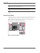
About This Guide Table 1: Location of Server Labels Item Component Item Component 1 I/O board removal label 6 I/O board configuration label 2 Hot Plug RAID Memory cartridge operation label 7 System board components label 3 System status LED indicators label 8 Rear connectors label 4 Removing power and media module label 9 Removing host module label 5 Front components label Related Documents For additional information on the topics covered in this guide, refer to the following document
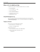
About This Guide Where to Go for Additional Help In addition to this guide, the following information sources are available: • User documentation • Service Quick Reference Guide • Service training guides • Service advisories and bulletins • QuickFind information services • Insight Manager software Integrated Management Log The server includes an integrated, nonvolatile management log that contains fault and management information.
1 Illustrated Parts Catalog This chapter provides the illustrated parts breakdown and a spare parts list for the HP ProLiant DL740 server. See the table following each illustration for the names of referenced spare parts.
Illustrated Parts Catalog System Chassis Figure 1-1: System chassis exploded view Table 1-1: System Chassis Spare Parts List Item Description Spare Part Number System Chassis 1 Power and media module 2 System chassis with access panels 3 Host module without PCI-X riser 280612-001 Assemblies 4 Cable management system reel assembly and rails 280620-001 4a Cable management arm* 326779-001 4b Cable management/Velcro* 342294-001 *Not shown 1-2 HP ProLiant DL740 Server Maintenance and Serv
Illustrated Parts Catalog Power and Media Module Figure 1-2: Power and media module exploded view Table 1-2: Power and Media Module Spare Parts List Item Description Spare Part Number Power and Media Module Components 1 Power and media module chassis 2 Power and media module bezel 3 Backplane board 280618-001 4 Power supplies 285381-001 continued HP ProLiant DL740 Server Maintenance and Service Guide HP CONFIDENTIAL Codename: RedStar Part Number: 270853-004 Last Saved On: 2/10/04 3:45 PM 1-
Illustrated Parts Catalog Table 1-2: Power and Media Module Spare Parts List continued Item Description Spare Part Number Mass Storage 5 LVDS 1-inch hard drive blank 313046-001 6 Wide Ultra3 hard drive with tray, 18.2-GB, 1-inch, 10000 rpm 152190-001 Wide Ultra3 hard drive with tray, 36.4-GB, 1-inch, 10000 rpm* 177986-001 Wide Ultra3 hard drive with tray, 18.2-GB, 1-inch, 15000 rpm* 189395-001 U320 Universal hard drive with tray, 36.
Illustrated Parts Catalog Host Module Figure 1-3: Host module exploded view HP ProLiant DL740 Server Maintenance and Service Guide HP CONFIDENTIAL Codename: RedStar Part Number: 270853-004 Last Saved On: 2/10/04 3:45 PM 1-5
Illustrated Parts Catalog Table 1-3: Host Module Spare Parts List Item Description Spare Part Number Host Module Components 1 Host module chassis 2 PCI-X Hot Plug switchboard with cable 280615-001 3 Processor board 314379-001 4 Processor board cover 320104-001 Processors 5 Processor (1.5 GHz with 1-MB cache), clip, and heatsink 319952-001 Processor (2.0 GHz with 1-MB cache), clip, and heatsink* 327839-001 Processor (2.0 GHz with 2-MB cache), clip, and heatsink* 319953-001 Processor (2.
Illustrated Parts Catalog Miscellaneous Table 1-4: Miscellaneous Spare Parts List Item Description Miscellaneous plastics* Spare Part Number 280624-001 a) Guide, card, processor b) Puller assembly, PCI, LV c) Receptacle, interconnect, AC d) Guide, memory e) Gear, rack, processor f) Guide, fan g) Lightpipe, fan h) Divider, upper fan i) Ejector, right j) Ejector, left k) Grill, exhaust, chassis rear l) Retainer, cardguide, PCI, CBN (quantity 9) m) Assembly, PCI latch and base, PCI, CBN n) Baffle, po
2 Service Preparation Safety Considerations Before performing service procedures, review the following safety information. Electrostatic Discharge Information A discharge of static electricity can damage static-sensitive devices or microcircuitry. Proper packaging and grounding techniques are necessary precautions to prevent damage. To prevent electrostatic damage, observe the following precautions: • Transport products in static-safe containers, such as conductive tubes, bags, or boxes.
Service Preparation Rack Warnings and Precautions WARNING: To reduce the risk of personal injury or damage to the equipment, be sure that: • The leveling jacks are extended to the floor. • The full weight of the rack rests on the leveling jacks. • The stabilizers are attached to the rack if it is a single-rack installation. • The racks are coupled in multiple-rack installations. • Only one component is extended at a time.
Service Preparation WARNING: To reduce the risk of personal injury from hot surfaces, allow the internal system components to cool before touching them. CAUTION: Because the HP ProLiant DL740 server does not have safety interlocks, it is possible for a unit to be operated without the cover and air baffles properly installed. This could cause thermal damage in the system and could void the warranty. The rack-mountable HP ProLiant DL740 server should always be operated with the system unit cover on.
Service Preparation Server Modules In the HP ProLiant DL740 server, options and accessories are easily accessed through top access panels and two removable modules: the power and media module, and the host module. See Figure 2-1, Figure 2-2, and Figure 2-3 for identification of these modules and other components.
Service Preparation Figure 2-2: Power and media module components Item Description 1 Ultra3 hard drive SCSI ID 0 2 Ultra3 hard drive SCSI ID 1 3 Ultra3 hard drive SCSI ID 2 4 Ultra3 hard drive SCSI ID 3 5 Power supply 1 6 Power On/Standby switch 7 DVD-ROM drive 8 1.
Service Preparation Figure 2-3: Host module components Item Description 1 Processor board 1 2 Processor board 2 3 Memory cartridge 1 4 Memory cartridge 2 5 Memory cartridge 3 6 Memory cartridge 4 7 Memory cartridge 5 8 I/O board 9 System fan 2 10 System fan 1 For details on cable connections, refer to Chapter 6 in the HP ProLiant DL740 Server User Guide.
Service Preparation Table 2-1 describes the contents of the modules and how to access the components. Table 2-1: Module Components and Access Module Contents To Access PCI Hot Plug expansion slots Open the top access panels. Configuration switches Open the top access panels. Fans 1 and 2 Open the top access panels. Processor boards Open the top access panels, open the processor board cover, and remove the processor boards.
Service Preparation To service the HP ProLiant DL740 server, you might need the following: • Flat-blade screwdriver (4 mm) • Torx T-15 screwdriver • T8 screwdriver • Phillips screwdriver • HP SmartStart CD: — Drive Array Advanced Diagnostics (DAAD) software — Array Diagnostics Utility (ADU) software — ROM-Based Inspect Utility — ROM-Based Diagnostics System Interconnect LEDs The system interconnect LEDs on the ProLiant DL740 server provide a closed-loop checking mechanism for verifying proper com
Service Preparation Non-Hot-Plug Procedures You must power down the server to perform non-hot-plug procedures. WARNING: To reduce the risk of electric shock or damage to the equipment, disconnect power from the server by unplugging all power cords from either the electrical outlet or the server. In systems with multiple power supplies, you must disconnect all the power cords to completely remove power from the system.
Service Preparation 5. Disconnect all power cords from the server to disable power to the server. For some removal and replacement procedures, you must remove the server from the rack and place it on a sturdy table or workbench. Refer to the HP ProLiant DL740 Server User Guide for further instructions. Powering Up the Server When you power up the server, it should go through the following sequence. Record any discrepancies and error messages that occur.
Service Preparation 4. The system activity LEDs (NIC1, NIC2, and Media) begin to blink in sequence until the memory initialization is complete. Figure 2-5: System activity LEDs 5. Check the hard drive LEDs on the front of the server. The hard drive LEDs should blink. If the LEDs do not light, verify that the hard drives are fully installed in the system and that the array bypass is initialized. 6. Check the DIMM status LEDs.
Service Preparation Power-On Self-Test (POST) As the POST process continues during server power-up, you need to check the monitor for the following information, displayed in sequence: 1. HP initialization screen 2. System ROM family and date 3. Memory initialization, memory detected, and redundant memory The system briefly displays the F1 prompt to open the Memory Configuration Manager.
Service Preparation Press the F1 key to enter the Memory Configuration Manager. This ROM-based tool, shown in Figure 2-7, is used to examine and upgrade the server memory configuration. Figure 2-7: Memory Configuration Manager 4. Processor initialization information. The number, speed, and cache size of each processor is listed as it initializes. 5. The system briefly displays the F8 prompt to configure the iLO using iLO RBSU. 6. Storage controller information.
Service Preparation 7. The system briefly displays the F9 and F10 prompts. Figure 2-8: System prompts Press the F9 key to start RBSU or the F10 key to open the System Maintenance Menu. Re-entering the Server Serial Number After you replace the server host module or clear the NVRAM, you must re-enter the server serial number. To re-enter the serial number: 1. During the server startup sequence, press the F9 key to access RBSU. 2. Select the System Options menu. 3. Select Serial Number.
3 Chassis Components Removal and Replacement Procedures Top Access Panels WARNING: To reduce the risk of personal injury from hot surfaces, allow the internal system components to cool before touching them. CAUTION: When the server is powered on, the access panels must be installed for proper system cooling. Otherwise, component stress and permanent equipment damage can result. Open the top access panels to access the PCI Hot Plug expansion slots, system fans, and configuration switches. 1.
Chassis Components Removal and Replacement Procedures Cable Management System The cable management system is installed on the back of the server mounted in the rack and consists of two cable management system reel assemblies and a cable management system harness. To remove the cable management system: 1. Detach the cable harness hook 5 for the loop labeled 5 on the server rail. 2. Detach the cable harness hook 4 from reel 4. 3. Detach the cable harness hook 3 from reel 3. 4.
Chassis Components Removal and Replacement Procedures 8. Rotate the second reel, labeled 3, until it unlocks and remove it from the left of the server chassis. Figure 3-3: Removing reel 3 To reinstall the cable management system, reverse steps 1 through 8.
4 Host Module Removal and Replacement Procedures Host Module The host module is located at the rear of the server. Remove it to replace or service non-hot-plug components or to access other components in the host module. IMPORTANT: You must re-enter the server serial number through RBSU after you replace the host module. Refer to the “Re-entering the Server Serial Number” section in Chapter 2.
Host Module Removal and Replacement Procedures 4. Push down the processor board lever latch to release the lever (1). 5. Lift up the processor board lever to release the board (2), and lift the processor board out of the module (3). Figure 4-1: Removing the processor board 6. Push in on the sides of the cam levers on the host module (1), and rotate the top of the levers downward (2), as shown in Figure 4-2. 7. Pull the host module out of the chassis (3).
Host Module Removal and Replacement Procedures 8. Set the host module aside for servicing non-hot-plug components. WARNING: To reduce the risk of personal injury from hot surfaces, allow the internal system components to cool before touching them. NOTE: Top panel labels provide instructions about installing expansion boards, setting switches, and installing hot-plug fans, along with information about PCI Hot Plug. Refer to Chapter 5 for hot-plug procedures. To reassemble the server: 1.
Host Module Removal and Replacement Procedures Processor Boards and Processors Identifying The ProLiant DL740 server is capable of supporting up to eight Intel® Xeon processors and is shipped with four or eight processors already installed. The ProLiant DL740 server supports two processor boards located in the host module.
Host Module Removal and Replacement Procedures The ProLiant DL740 server supports four or eight Intel Xeon processors MP. • All processors must be the same speed, cache size, and stepping. NOTE: Stepping refers to the processor revision. • Processor board slot 1 must always be populated with a processor board to properly terminate the processor bus. NOTE: If the server has one processor board (four processors), processor board slot 2 is populated with a processor board air baffle.
Host Module Removal and Replacement Procedures Removing Processor Boards and Processors WARNING: The host module weighs more than 15.88 kg (35 lbs). HP recommends either removing ALL of the memory cartridges before handling the module or having two people handle the module together. To remove the processor boards and processors: 1. Power down the server. Refer to “Powering Down the Server” in Chapter 2.
Host Module Removal and Replacement Procedures 4. Push the lever latch forward to release the processor board lever (1). 5. Lift the processor board lever up (2) and lift the processor board out of the module (3). Figure 4-6: Removing the processor board 6. Push in the four tabs on the side of the processor board cover (1) and then lift the cover off the processor board (2). Figure 4-7: Removing the processor board cover 7. Turn over the processor board to access the processor clips.
Host Module Removal and Replacement Procedures 8. Lift the processor clip to unlock it (1) and then slide it (2) to remove it from the processor board. Figure 4-8: Removing the processor clip 9. Turn the processor board over to access the processors. 10. Open the processor release lever (1) and remove the processor (2). Figure 4-9: Removing the processor Reverse steps 1 through 10 to install a processor and the processor board.
Host Module Removal and Replacement Procedures Memory Cartridge Identifying The five Hot Plug RAID Memory cartridges are located in the front side of the host module. Each memory cartridge contains up to eight DIMMs.
Host Module Removal and Replacement Procedures Memory Cartridge Components The following figure and table show the various components of the memory cartridges.
Host Module Removal and Replacement Procedures Removing the Memory Cartridge To remove a memory cartridge from the ProLiant DL740 server: 1. Unlock the memory cartridge by sliding the cartridge lock open (1). IMPORTANT: If the memory cartridge is not required for continued operation (with at least four other memory cartridges installed, online, and error free), the memory cartridge power LED will turn off.
Host Module Removal and Replacement Procedures DIMM Overview The ProLiant DL740 server has five memory cartridges, each consisting of eight DIMMs. The server supports up to 32 GB of usable memory with 8 GB of redundant memory. Locating the DIMM Sockets Figure 4-13 and Table 4-1 detail the DIMM socket locations on the memory cartridge.
Host Module Removal and Replacement Procedures Installing DIMMs in the Cartridge CAUTION: When handling a DIMM, be careful not to touch any of the contacts. Doing so might damage the DIMM. IMPORTANT: Be sure that DIMMs are installed in the proper orientation. The DIMMs are keyed to ensure that they are installed correctly in the memory socket. Refer to the system documentation for details.
Host Module Removal and Replacement Procedures Hot-Replacing Memory If there is a problem with a DIMM in the server, the DIMM status LEDs will illuminate as either solid or blinking. If the DIMM status LED for a specific DIMM in a specific cartridge is solid, then the DIMM needs to be replaced. CAUTION: A redundant memory configuration is required when performing Hot Plug RAID Memory functions. • If all memory cartridges are online and error free, any memory cartridge can be removed.
Host Module Removal and Replacement Procedures PCI-X Hot Plug and Non-Hot-Plug I/O Expansion Boards The ProLiant DL740 server supports PCI-X Hot Plug. PCI-X Hot Plug and the operating system of the server work together to allow the following hot-plug actions: • Hot-replace—Allows you to replace a failed expansion board with an identical expansion board without powering down the server.
Host Module Removal and Replacement Procedures PCI Hot Plug Utility SmartStart software provides the PCI Hot Plug Utility for each operating system supported by the server. The PCI Hot Plug Utility is delivered as part of the HP Support Pack, which is available on the SmartStart CD and at the website: www.hp.com/servers/proliant/manage The PCI Hot Plug Utility is the user interface of the PCI Hot Plug architecture.
Host Module Removal and Replacement Procedures Locating the I/O Expansion Slots The I/O expansion slots are located in the host module and are accessed by sliding the server out of the rack and opening the top access panels, as described in Chapter 3. The I/O expansion slots are distributed among three separate PCI-X buses. WARNING: To reduce the risk of personal injury from hot surfaces, allow the internal system components to cool before touching them.
Host Module Removal and Replacement Procedures PCI Hot Plug LED Indicators The PCI Hot Plug amber and green LEDs (shown in the following figure for one slot) provide a visual reference for the status of each slot. The LEDs can be viewed from the rear of the server, as shown in Figure 4-16, or inside the host module, as shown in Figure 4-17.
Host Module Removal and Replacement Procedures Table 4-3 provides a description and slot status for the PCI Hot Plug LEDs and button, shown in Figure 4-17. Table 4-3: PCI Hot Plug LEDs and Button Amber LED 1 OK to Open Slot Condition and Status Off Slot does not require attention. On Slot requires attention. There could be a problem with the slot, the PCI board, or the driver. Check the green LED before opening the slot.
Host Module Removal and Replacement Procedures Removing or Replacing a Non-Hot-Plug Expansion Board CAUTION: Do not open the slot release lever unless the green PCI Hot Plug LED indicator is off. System power down and subsequent data loss could occur. To remove a non-hot-plug expansion board: 1. Power down the server. Refer to “Powering Down the Server” in Chapter 2. 2. Slide the server out of the rack. 3. Open the top access panel. Refer to “Top Access Panels” in Chapter 3. 4.
Host Module Removal and Replacement Procedures To replace a non-hot-plug expansion board: 1. Insert the PCI/PCI-X expansion board into the appropriate expansion slot (1), pushing firmly until the board is securely seated. 2. Close the expansion slot release lever from the rear of the unit to secure the board (2). Be sure that the lever latches into the closed position. Figure 4-19: Inserting the PCI/PCI-X expansion board 3. Connect the expansion board I/O cable as appropriate.
Host Module Removal and Replacement Procedures 4. Close the top access panel and slide the server into the rack. 5. Power up the server. Refer to “Powering Up the Server” in Chapter 2. 6. If necessary, run the ROM-Based Setup Utility, as described in the HP ProLiant DL740 Server User Guide. NOTE: Refer to the HP QuickSpecs for the ProLiant servers at www.hp.com for a list of supported I/O expansion boards.
Host Module Removal and Replacement Procedures Removing or Replacing a PCI Hot Plug Expansion Board To remove or replace a PCI Hot Plug expansion board: 1. Open the top access door of the server. 2. Use the PCI Hot Plug button or software application to notify the system to turn off power to the slot. Pushing the PCI Hot Plug button notifies the system to shut down operation of the expansion board; lifting the lever actually powers down the expansion slot.
Host Module Removal and Replacement Procedures 7. If you are replacing the board, install the new I/O expansion board. a. Close the slot release lever. b. Be sure that the lever latches into the closed position. c. Reconnect any I/O cables to the new board. d. Return power to the slot through the PCI Hot Plug button or software application. The green LED will flash during the power-up transition and will turn on when the power-up is complete.
Host Module Removal and Replacement Procedures Array Enabler Board/Integrated Array Bypass Kit The SmartArray 5i Controller is routed to the internal drives through the Array Enabler Board in the host module. The Integrated Array Bypass kit allows you to replace the Array Enabler board with a connector and cable that you can connect to an optional controller board. For information on the Integrated Array Bypass kit, refer to the installation instruction included with the kit.
Host Module Removal and Replacement Procedures 7. Slide the retaining clip (1) and remove the Array Enabler board from the server (2), as shown Figure 4-22. Figure 4-22: Removing the Array Enabler board NOTE: If an Array Bypass assembly is installed, disconnect the cable from the optional array controller, then remove the bypass assembly by sliding the retaining clip and remove the Array Bypass board from the server.
Host Module Removal and Replacement Procedures I/O Expansion Slot Dividers To remove the five I/O expansion slot dividers: 1. Power down the server. Refer to “Powering Down the Server” in Chapter 2. 2. Open the top access panel. Refer to “Top Access Panel” in Chapter 3. 3. Remove all installed expansion boards in slots 1 through 6. Refer to “Removing or Replacing a Non-Hot-Plug Expansion Board” in this chapter. 4.
Host Module Removal and Replacement Procedures Hot-Plug Fans The ProLiant DL740 server ships with two hot-plug fans. Fan 1 is closest to the front of the server. Each fan has an arrow-shaped status LED that indicates the status of the fan to which the arrow is pointing. Figure 4-24 shows an example of the hot-plug fan status LEDs: • Hot-plug fan 1 LED (1)—In this case, the LED is amber, which means that the fan needs attention or is not installed.
Host Module Removal and Replacement Procedures The ProLiant DL740 server comes equipped with fan attention LEDs located on the front of the server, shown in Figure 4-25.
Host Module Removal and Replacement Procedures Replacing a Hot-Plug Fan To replace a hot-plug fan: 1. Open the top access panels. 2. Squeeze the locking latch with your fingers (1) and lift the failed hot-plug fan out of the host module (2). Figure 4-26: Removing hot-plug fan 2 3. Lower the new hot-plug fan into the host module until it rests on the system board connector. Push the fan into the connector. The fan locking latch will lock into place. 4.
Host Module Removal and Replacement Procedures Input/Output Board The ProLiant DL740 server ships with a removable input/output board. To remove the I/O board: 1. Power down the server. Refer to “Powering Down the Server” in Chapter 2. 2. Remove the host module. Refer to “Removing the Host Module” in this chapter. 3. Remove the I/O expansion boards. Refer to “Removing I/O Expansion Boards” in this chapter. 4.
Host Module Removal and Replacement Procedures 6. Locate and remove the Torx tool. NOTE: If you have installed the integrated array bypass assembly, see “Removing the Integrated Array Bypass Assembly” in this chapter. Figure 4-28: Removing the Torx tool 7. Disconnect the I/O expansion board bracket by releasing the thumbscrews (1), and then lifting the bracket and sliding it towards you (2). Figure 4-29: Disconnecting the I/O expansion board bracket 8.
Host Module Removal and Replacement Procedures 9. Release the retention clip (1). 10. Insert the beveled wrench between the I/O board and the chassis (2) and turn the tool clockwise to unseat the board. 11. Depress the spring-loaded retainer on the right side of the bay (4) and lift the board out of the chassis (5).
Host Module Removal and Replacement Procedures System Board The system board is located in the bottom of the host module.
5 Power and Media Module Removal and Replacement Procedures The power supplies and mass storage in the HP ProLiant DL740 server are located in the power and media module. The power and media module can configure a maximum of four 1-inch hot-plug U320 Universal SCSI hard drives or Wide Ultra3 SCSI hard drives. The power and media module supports two non-hot-plug media drive bays: • One drive bay occupied by a 1.
Power and Media Module Removal and Replacement Procedures Removing the Power and Media Module WARNING: The power and media module weighs more than 15.88 kg (35 lbs). HP recommends removing both power supplies before handling the module, or having two people handle the module together. WARNING: The host module must be removed before attempting to remove the power and media module. CAUTION: Do not attempt to remove the power and media module while power is applied to the system.
Power and Media Module Removal and Replacement Procedures 6. Push in the levers on the power and media module (1), as shown in Figure 5-1. 7. Pull the power and media module out of the chassis (2) until it encounters the module stop latches. Figure 5-1: Opening the power and media module 8. Press in on the module stop latches (1) and pull the module out of the chassis (2), as shown in Figure 5-2.
Power and Media Module Removal and Replacement Procedures 9. To reassemble the server, slide the module in until the levers begin to rotate. Then push the levers shut until they snap into place. IMPORTANT: Check the System Interconnect status LEDs to ensure that the module is properly seated. Refer to “System Interconnect LED Indicators” in Chapter 7. Hot-Plug Power Supplies The ProLiant DL740 server ships with two hot-plug power supplies.
Power and Media Module Removal and Replacement Procedures Removing and Replacing a Hot-Plug Power Supply To remove and replace a hot-plug power supply with the system power on: 1. Press the power supply latch to release the power supply handle (1). 2. Rotate the power supply handle outward (2) and slide the power supply out of the chassis (3), as shown in Figure 5-3. Use both hands when removing the power supply to support its weight. Power supplies weigh 4.09 kg (9 lbs) each.
Power and Media Module Removal and Replacement Procedures 4. Slide the hot-plug power supply into the power supply cage until the supply is seated securely (1), as shown in Figure 5-4. This action automatically pushes the spring-loaded trap door open. 5. Rotate the handle inward to lock the power supply into place (2, 3). The power supply fan starts immediately if the system is running. IMPORTANT: The power supply fan will start and run at low speed if the system is in Standby mode.
Power and Media Module Removal and Replacement Procedures Power Supply LED Indicators Each power supply has status and AC power LEDs. Refer to Figure 5-5 and Table 5-1 for a detailed description of both indicators. Figure 5-5: Power supply LEDs Table 5-1: Power Supply LEDs Item Condition Meaning Green blinking AC power is connected to this power supply. System is in standby mode. Green Normal operation. Off No AC power. Amber Fault detected in this power supply. Replace power supply.
Power and Media Module Removal and Replacement Procedures Power and Media Module Bezel To remove the power and media module bezel: 1. Power down the server. Refer to “Powering Down the Server” in Chapter 2. 2. Remove both power supplies. Refer to “Removing and Replacing a Hot-Plug Power Supply” in this chapter. 3. Remove the power and media module. Refer to “Removing the Power and Media Module” in this chapter. 4.
Power and Media Module Removal and Replacement Procedures 5. Remove the LED bezel by lifting it off the chassis. 6. Press the tabs on both sides of the bezel to release it from the chassis (2). 7. Pull the power and media module bezel away from the chassis (3). Figure 5-7: Removing the bezels from the power and media module Reverse steps 1 through 7 to replace the power and media module bezel.
Power and Media Module Removal and Replacement Procedures When replacing hot-plug hard drives in a fault-tolerant configuration, follow these guidelines: • Never remove more than one drive at a time. When a drive is replaced, the controller uses data from the other drives in the array to reconstruct data on the replacement drive. If more than one drive is removed, a complete data set is not available to reconstruct data on the replacement drive.
Power and Media Module Removal and Replacement Procedures Hard Drive Blank To remove a hard drive blank from a hard drive bay: 1. Push the side of the retaining clips inward (1). 2. Pull the hard drive blank from the bay (2). Figure 5-8: Removing a hard drive blank Reverse steps 1 and 2 to replace a hard drive blank.
Power and Media Module Removal and Replacement Procedures Removing a Hot-Plug SCSI Hard Disk Drive To remove a hot-plug SCSI hard disk drive: 1. To remove a hot-plug SCSI hard drive, push the release button on the left of the drive and rotate the hot-plug drive ejector lever outward to unlock the drive. 2. Pull the drive out of the drive bay. Figure 5-9: Removing a hot-plug SCSI hard drive Reverse steps 1 and 2 to replace a hot-plug hard drive.
Power and Media Module Removal and Replacement Procedures Removing the DVD/CD-ROM Drive The half-height universal media bay supports hot-pluggable IDE devices and ships standard with a DVD-ROM drive. The bay also supports other removable media devices, such as a CD-ROM drive. 1. Locate the DVD drive on the front of the server in the universal media bay. 2. The universal media bay ejector button is recessed.
Power and Media Module Removal and Replacement Procedures Removable Media Assembly The half-height universal media bay supports hot-pluggable IDE devices and ships standard with a DVD-ROM drive. The bay also supports other removable media devices, such as a CD-ROM drive. NOTE: To replace the 1.44-MB diskette drive, the removable media assembly must be removed. To remove the removable media assembly: 1. Remove the power and media module. Refer to “Removing the Power and Media Module” in this chapter. 2.
Power and Media Module Removal and Replacement Procedures 3. Remove the LED bezel by lifting it off the chassis (1). 4. Disconnect the two LED signal cables by gently lifting the cable clamps (2), and then sliding the released cables out of the connector (3). 5. Pull the LED signal cables clear of the top of the power and media module. This provides access to the thumbscrew and cables connected to the removable media assembly. CAUTION: The LED signal cable connector clamps can be broken if forced open.
Power and Media Module Removal and Replacement Procedures 6. Disconnect the DVD/CD-ROM/diskette drive signal cable from the device interface board (1). 7. Disconnect the media drive bay and SCSI hard drive power cable from the device interface board (2). 8. Disconnect the Power On/Standby/UID switch cable from the midplane (3). Figure 5-13: Disconnecting the drive and power cables 9. Remove the power and media module bezel. Refer to “Power and Media Module Bezel” in this chapter. 10.
Power and Media Module Removal and Replacement Procedures Power and Media Module Cable Routing Diagram Figure 5-15: Power and media module cable routing Item Description 1 DVD/CD-ROM/Diskette drive signal cable 2 SCSI hard drive signal cable 3 Media drive bay and SCSI hard drive power cable 4 Power On/Standby/LED/UID/switch assembly cable HP ProLiant DL740 Server Maintenance and Service Guide HP CONFIDENTIAL Codename: Jethro Part Number: 270853-004 Last Saved On: 2/10/04 3:51 PM 5-17
6 Diagnostic Tools This chapter provides an overview of the software and firmware diagnostic tools available for the HP ProLiant DL740 server.
Diagnostic Tools Diagnostic Tools Utility Overview The following utilities were developed to assist in diagnosing problems, testing the hardware, and monitoring and managing HP server hardware. Table 6-1: Diagnostic Tools Tool What it is How to run it Enterprise Diagnostics LX 32 Utility This utility assists in testing and verifying operation of HP hardware. If problems are found, Diagnostics isolates failures down to a replaceable part, whenever possible.
Diagnostic Tools Table 6-1: Diagnostic Tools continued Tool What it is How to run it Survey Utility This online information-gathering agent runs on servers, gathering critical hardware and software information from various sources. It is utility for servers running Windows NT or NetWare. Install the Survey Utility from SmartStart, the Integration Maintenance Utility, or the Management CD.
Diagnostic Tools Table 6-1: Diagnostic Tools continued Tool What it is How to run it Array Diagnostics Utility (ADU) ADU is a Windows-based tool designed to run on all HP systems that support HP array controllers. The two main functions of ADU are: Use the information provided in the Array Diagnostics Utility (ADU). • To collect all possible information about the array controllers in the system. • To generate a list of detected problems.
7 Connectors, Switches, and LED Indicators Connectors This section contains graphics and tables that show the connector locations on the HP ProLiant DL740 server. Rear Panel Connectors Connect any peripheral devices to the connectors located on the rear of the server. Figure 7-1 identifies the peripheral connectors on the back of the server. WARNING: To reduce the risk of electrical shock or fire, do not plug telecommunications/telephone connectors into the NIC connectors.
Connectors, Switches, and LED Indicators Table 7-1: Rear Panel Connectors Item 7-2 Description 1 AC power port 2 AC power port 3 USB port 4 UID LED/Switch 5 iLO port 6 Keyboard connector 7 Mouse connector 8 Video port 9 Serial connector 10 NIC port 2 11 NIC port 1 HP ProLiant DL740 Server Maintenance and Service Guide HP CONFIDENTIAL Codename: Jethro Part Number: 270853-004 Last Saved On: 2/10/04 3:53 PM
Connectors, Switches, and LED Indicators System Board The system board is located in the bottom of the host module. Refer to Figure 7-2 to identify components on the system board.
Connectors, Switches, and LED Indicators I/O Board Components Figure 7-3: I/O board components Item Description 1 Array enabler board 2 I/O board switch bank (SW7) 3 PCI-X hot-plug cable connector 4 PCI-X slot 1 5 PCI-X slot 2 6 PCI-X slot 3 7 PCI-X slot 4 8 PCI-X slot 5 9 PCI-X slot 6 The operating system detects PCI devices in the following slot order: 5-6-1-2-3-4.
Connectors, Switches, and LED Indicators Switches This section contains graphics and tables showing switch location and settings for the host board. I/O Board Configuration Switches The I/O board switch bank is located on the inside edge of the I/O board near the Array Enabler board and I/O expansion slots 1 and 2.
Connectors, Switches, and LED Indicators LED Indicators Status LEDs are located on the front, back, and inside of the server. These LEDs communicate the current status of varying aspects of the components and operations, aiding you in diagnosing problems. The following ProLiant DL740 server LEDs are explained in this chapter.
Connectors, Switches, and LED Indicators System Power LED Switch Figure 7-5 shows the location of the system power LED switch.
Connectors, Switches, and LED Indicators Unit Identification LED Switches (Front and Rear) The ProLiant DL740 server offers Unit Identification (UID) LED switches to aid in identifying specific servers in a rack environment. Each ProLiant DL740 server has two unit identification switches, one on the front of the server and one on the back of the server. When activated from the front of the server, the Front UID switch illuminates two LEDs.
Connectors, Switches, and LED Indicators System Interconnect LED Indicators To prevent damage to critical system components, the ProLiant DL740 server will not power up if it detects that certain components are not installed or are installed incorrectly. The system interconnect LEDs provided with ProLiant DL740 servers provide a closed-loop checking mechanism for verifying proper component mating and interconnections between critical server components.
Connectors, Switches, and LED Indicators System Attention LED Indicators Figure 7-8: System attention LEDs Item Description 1 Temperature attention 2 Hot-plug fan 1 attention 3 Hot-plug fan 2 attention 4 Processor board 1 attention 5 Processor board 2 attention The temperature attention LED has two possible states: 7-10 • Amber LED—The first temperature threshold has been reached. Fans are at high speed.
Connectors, Switches, and LED Indicators System Activity LED Indicators Figure 7-9: System activity LEDs Item Description 1 NIC 1 link status activity LED 2 NIC 2 link status activity LED 3 DVD/CD-ROM activity LED HP ProLiant DL740 Server Maintenance and Service Guide HP CONFIDENTIAL Codename: Jethro Part Number: 270853-004 Last Saved On: 2/10/04 3:53 PM 7-11
Connectors, Switches, and LED Indicators Hot-Plug SCSI Hard Drive LED Indicators The hot-plug SCSI hard drive LEDs, located on each physical drive, are visible on the front of the server or external storage unit. They provide: (1) Activity, (2) Power/Online, and (3) Fault status for each corresponding drive when configured as a part of an array and attached to a powered-on controller. Their behavior might vary, depending on the status of other drives in the array.
Connectors, Switches, and LED Indicators Figure 7-11: SCSI hard drive LEDs HP ProLiant DL740 Server Maintenance and Service Guide HP CONFIDENTIAL Codename: Jethro Part Number: 270853-004 Last Saved On: 2/10/04 3:53 PM 7-13
Connectors, Switches, and LED Indicators Power Supply LED Indicators Each power supply has status and AC power LEDs. See Figure 7-12 and Table 7-3 for a detailed description of both indicators. Figure 7-12: Power supply LEDs Table 7-3: Power Supply LEDs Item 1 AC Power Condition Meaning Green blinking AC power is connected to this power supply. System is in standby mode. Green Normal operation. Off No AC power. Fault detected in this power supply. Must replace power supply.
Connectors, Switches, and LED Indicators Hot-Plug Fan LED Indicators The ProLiant DL740 server ships with two hot-plug fans. Fan 1 is closest to the front of the server. Each fan has an arrow-shaped status LED that indicates the status of the fan the arrow is pointing to. Figure 7-13 shows an example of the hot-plug fan status LEDs: • Hot-plug fan 1 LED (1)—In this case, the LED is amber, which means that the fan needs attention or is not installed.
Connectors, Switches, and LED Indicators PCI Hot Plug LED Indicators The PCI Hot Plug amber and green LEDs provide a visual reference on the status of each slot. The LEDs are viewed from the rear of the server, as shown in Figure 7-14, or by opening the top access panels, as shown in Figure 7-15.
Connectors, Switches, and LED Indicators Figure 7-15: PCI Hot Plug LEDs in the host module A description and slot status for the PCI Hot Plug LEDs and button shown in Figure 7-15 are provided in Table 7-4. Table 7-4: PCI Hot Plug LEDs and Button Amber LED 1 OK to Open Slot Condition and Status Off Slot does not require attention. On Slot requires attention. There could be a problem with the slot, the PCI board, or the driver. Check the green LED before opening the slot.
Connectors, Switches, and LED Indicators Memory Cartridge LED Indicators Each memory cartridge has two LEDs that indicate its status.
Connectors, Switches, and LED Indicators DIMM Status LED Indicators The ProLiant DL740 server has LEDs for each DIMM in the five memory cartridges. These LEDs are used to determine the status of memory installed in the server.
Connectors, Switches, and LED Indicators LED Indicator State Definitions Table 7-6 provides descriptions of the possible LED states of the memory cartridges.
8 Physical, Operating, and Performance Specifications This section provides physical, operating, and performance specifications for the following components of the HP ProLiant DL740 server: • Server • Power supply • Dual inline memory module (DIMM) • 1.
Physical, Operating, and Performance Specifications Server Specifications Table 8-1: HP ProLiant DL740 Server Specifications Dimensions Height 30.5 cm (12.0 in) Depth 68.5 cm (27.0 in) Width 44.5 cm (17.5 in) Weight (no drives and two power supplies) 56.
Physical, Operating, and Performance Specifications Power Supply Specification Table 8-2: Power Supply Specifications General specifications Full output rating To 40° C and 1,525 m (to 104° F and 5,000 ft) To 32° C and 3,050 m (to 90° F and 10,000 ft) (derate linearly) Minimum load 1.0 A on + 5 V output 1.0 A on + 12 V output 0.5 A on + 3.
Physical, Operating, and Performance Specifications Dual Inline Memory Module Specifications Table 8-3: DIMM Specifications Size 256 MB, 512 MB, or 1 GB Speed 60 ns or faster Upgrade requirement Bank of two DIMMs; must be same type, size, speed, and manufacturer Type Buffered ECC protected DIMMs; SDRAM 1.44-MB Diskette Drive Table 8-4: Diskette Drive Specifications Size 3.5 in LED indicators (front panel) Green Read/write capacity per diskette (high/low density) 1.
Physical, Operating, and Performance Specifications DVD-ROM Drive Table 8-5: DVD-ROM Drive Specifications Dimensions Height 4.29 cm (1.69 in) Width 15.0 cm (5.75 in) Depth 20.8 cm (8.19 in) Weight 1200 g (2.
Physical, Operating, and Performance Specifications Table 8-5: DVD-ROM Drive Specifications continued Laser parameters Type Semiconductor laser GaA1As Wave length 780 +/- 25 nm Divergence angle 53.5° +/- 1.5° Output power 0.14 mW Interface IDE (ATAPI) 24X Max IDE CD-ROM Drive Table 8-6: 24X Max IDE CD-ROM Drive Specifications Dimensions Height 4.29 cm (1.69 in) Width 15.0 cm (5.75 in) Depth 20.8 cm (8.19 in) Weight 1200 g (2.
Physical, Operating, and Performance Specifications Table 8-6: 24X Max IDE CD-ROM Drive Specifications continued Access times (typical) Full stroke 200 ms Random 100 ms Cache/buffer 128 KB Startup time (typical) >7s Stop time >4s Audio output level Line out 0.7 VRMS at 47 Ohms Headphone 0.6 VRMS at 32 Ohms (maximum width) Laser parameters Type Semiconductor laser GaA1As Wave length 780 +/- 25 nm Divergence angle 53.5° +/- 1.5° Output power 0.
Physical, Operating, and Performance Specifications Hot-Plug U320 SCSI Hard Drives Table 8-6: Hot-Plug U320 SCSI Hard Drives 36.4-GB 72.8-GB 146.8-GB 18.2-GB 36.4-GB 72.8-GB Capacity 36419.3 MB 72839.1 MB 146815.7 MB 18209.3 MB 36419.3 MB 72839.1 MB Height 1.0 in 1.0 in 1.0 in 1.0 in 1.0 in 1.0 in Size 3.5 in 3.5 in 3.5 in 3.5 in 3.5 in 3.
Physical, Operating, and Performance Specifications Hot-Plug Ultra3 SCSI Hard Drives Table 8-8: Hot-Plug Ultra3 SCSI Hard Drives 18.2-GB 36.4-GB 18.2-GB Capacity 18209.3 MB 36419.3 MB 18209.3 MB Height 1.0 in 1.0 in 1.0 in Size 3.5 in 3.5 in 3.5 in Interface Wide-Ultra3 SCSI Wide-Ultra3 SCSI Wide-Ultra3 SCSI Transfer rate 160 MB/s 160 MB/s 160 MB/s Seek time (typical, including setting) Single track 0.8 ms 0.9 ms 0.7 ms Average 5.2 ms 5.7 ms 3.9 ms Full stroke 12.0 ms 12.
Physical, Operating, and Performance Specifications Smart Array 5i Controller Table 8-9: Smart Array 5i Controller Specifications Temperature range Operating 10° to 35° C (50° to 95° F) Shipping -30° to 60° C (-22° to 140° F) Relative humidity range (noncondensing) Operating 20% to 80% Nonoperating 5% to 90% Maximum drives supported 4 Logical drives supported 32 Simultaneous drive transfer channels 2 Data transfer method 32/64-bit PCI bus master interface Total transfer rate 320 MB/s (160
Physical, Operating, and Performance Specifications NC7781 PCI-X Gigabit Server Adapter Table 8-10: NC7781 PCI-X Gigabit Server Adapter Network interface 10Base-T/100Base-TX Compatibility IEEE 802.3i, 802.3u, 802.3x, 802.3ab, 802.3ad compliant PCI-X 1.0, PCI 2.2, ACPI v1.
Index Symbols and Numbers D 6-slot hot-plug basket 4-27 battery part number 1-7 bezels, power and media module 5-8 blanking panels, hard drives 1-4, 5-11 boards memory 1-6 processor part numbers 1-6 boards, I/O connectors 7-4 button, PCI Hot Plug 4-17 DAAD (Drive Array Advanced Diagnostics) location 2-8 overview 6-4 diagnostic tools location 2-8 overview 6-2 DIMMs (Dual Inline Memory Modules), part numbers 1-6 diskette drives location 5-1 part number 1-4 specifications 8-4 Drive Array Advanced Diagnost
Index G grounding viii grounding plug vii grounding procedures 2-1, 2-2 H hard drives blanks 5-11 LED indicators 7-12 part numbers 1-4 help resources x host module accessing 2-7 exploded view 1-5 installing memory 4-9 spare parts list 1-6 Hot Plug RAID Memory DIMM configurations 4-12 installation 4-13 LED indicators 7-19 replacing DIMMs 4-14 hot surface warning 4-1 hot surfaces 4-6 hot-plug components baskets 4-27 fans 4-28, 7-15 hard drives 7-12 hot-replace feature 4-14 HP authorized reseller x I I/O co
Index R T rear panel configuration 7-1 removing components hard drives 5-9 host module 4-1, 5-2 replacing components, hot-plug SCSI hard drives 5-9 ROM-based Setup Utility (RBSU) 6-3 technician notes vii telephone numbers x tools required for service procedures 2-8 top access panels 3-1 transporting parts 2-1 troubleshooting, startup sequence 2-10 U S SDRAM DIMMs, part numbers 1-6 Smart Array Controller specifications 8-10 SmartStart, utilities 2-8 software required for service procedures 2-8 specifica