HP ProLiant DL760 Generation 2 Server Maintenance and Service Guide February 2004 (Third Edition) Part Number 201262-003
© Copyright 2003, 2004 Hewlett-Packard Development Company, L.P. The information contained herein is subject to change without notice. The only warranties for HP products and services are set forth in the express warranty statements accompanying such products and services. Nothing herein should be construed as constituting an additional warranty. HP shall not be liable for technical or editorial errors or omissions contained herein. Microsoft, Windows, and Windows NT are U.S.
Contents About This Guide Audience Assumptions............................................................................................................................... vii Technician Notes........................................................................................................................................ vii Where to Go for Additional Help.............................................................................................................. viii Integrated Management Log ...
Contents Chapter 4 Media Module Removal and Replacement Procedures Media Module............................................................................................................................................4-2 Media Module Bezel..................................................................................................................................4-4 Integrated Management Display ..........................................................................................................
Contents Chapter 7 Diagnostic Tools Diagnostic Tools Utility Overview ........................................................................................................... 7-2 For More Information................................................................................................................................ 7-4 Chapter 8 Connectors, Switches, and LED Indicators Connectors..................................................................................................................
About This Guide This maintenance and service guide can be used for reference when servicing the HP ProLiant DL760 Generation 2 server. WARNING: To reduce the risk of personal injury from electric shock and hazardous energy levels, only authorized service technicians should attempt to repair this equipment. Improper repairs can create conditions that are hazardous. Audience Assumptions This guide is for service technicians.
About This Guide CAUTION: To properly ventilate the system, you must provide at least 7.6 cm (3.0 in.) of clearance at the front and back of the server. CAUTION: The computer is designed to be electrically grounded (earthed). To ensure proper operation, plug the AC power cord into a properly grounded AC outlet only. NOTE: Any indications of component replacement or printed wiring board modifications may void any warranty.
1 Illustrated Parts Catalog This chapter provides the illustrated parts breakdown and a spare parts list for the HP ProLiant DL760 server. Refer to the table following each illustration for the names of referenced spare parts.
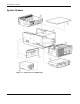
Illustrated Parts Catalog System Chassis Figure 1-1: System chassis exploded view 1-2 HP ProLiant DL760 Generation 2 Server Maintenance and Service Guide
Illustrated Parts Catalog Table 1-1: System Chassis Spare Parts List Item Description Spare Part Number System Chassis 1 System 2 I/O 3 chassis lid 122214-001 Processor and memory module (without processors) 4 Media module Heatsink 278466-001 319945-001 * Ramp* Memory module bezel* 5 I/O module with PCI-X I/O board 339661-001 System Components 6 Hot-plug power supply 1150 W 122235-001 7 System midplane assembly 316747-001 *Not shown HP ProLiant DL760 Generation 2 Server Maintenance an
Illustrated Parts Catalog Media Module Figure 1-2: Media module exploded view 1-4 HP ProLiant DL760 Generation 2 Server Maintenance and Service Guide
Illustrated Parts Catalog Table 1-2: Media Module Spare Parts List Item Description Spare Part Number Media Module Components 1 Media module 319945-001 a) Drive tray module* b) Drive cage assembly* c) Media module bezel 2 IMD with cable, panel, LED 271930-001 3 Power switch assembly with LED 122233-001 Mass Storage 4 Wide Ultra3 hard drive with tray, 18.2-GB, 1-inch, 10000 rpm 152190-001 Wide Ultra3 hard drive with tray, 36.
Illustrated Parts Catalog Processor and Memory Module Figure 1-3: Processor and memory module exploded view 1-6 HP ProLiant DL760 Generation 2 Server Maintenance and Service Guide
Illustrated Parts Catalog Table 1-3: Processor and Memory Module Spare Parts List Item Description Spare Part Number Processor and Memory Module Components 1 Processor and memory module 278466-001 2 Processor board 314379-001 3 Processor cover 320104-001 4 Processor board air baffle and label 323754-001 5 Memory riser board 278467-001 Processors 6 Processor (1.5 GHz with 1-MB cache), clip, and heatsink 319952-001 Processor (2.
Illustrated Parts Catalog I/O Module Figure 1-4: I/O module exploded view 1-8 HP ProLiant DL760 Generation 2 Server Maintenance and Service Guide
Illustrated Parts Catalog Table 1-4: I/O Module Spare Parts List Item Description Spare Part Number I/O Module Components 1 I/O module 278457-001 a) PCI-X I/O board b) PCI-X Hot Plug switch board cable 2 Array enabler board 122232-001 3 Hot-plug 11-slot basket with dividers (quantity 10) and puller assembly (quantity 10) 323753-001 4 NC7770 PCI-X Gigabit Server Adapter 10/100/1000 TX UTP NIC 284848-001 NC7170 Dual Port PCI-X Gigabit Server Adapter* 313586-001 5 Hot-plu g fan 278469-001
Illustrated Parts Catalog Miscellaneous Table 1-5: Miscellaneous Spare Parts List Item Description 1 Miscell Spare Part Number aneous plastics* 278460-001 a) Cover, rack rail b) Retainer, cardguide, double c) Retain er, cardguide d) Gear, ejector, processor/memory riser e) Guide, card, processor f) Guide, fan, left g) Guide, fan, right h) Plenum, fan cage i) PCA, SW/LED 11-slot hot-plug PCI j) Cover, cartridge k) Bezel, top memory cage l) Hot-plug 11-slot basket with dividers (quantity 10) and puller
Illustrated Parts Catalog Table 1-5: Miscellaneous Spare Parts List continued Item 2 Description Lever ejector kit, miscellaneous* Spare Part Number 278461-001 Lever, memory cartridge Latch, memory cartridge Lever, processor PCA Spring, processor board / memory riser board and right lever Latch, processor board / memory riser board Lever, ejector, memory riser board Spring, memory cartridge, ZINC b) Ejector, right, I/O drawer c) Ejector, left, I/O drawer Assembly, ejector, drive cage, right, graphite As
2 Service Preparation Safety Considerations Before performing service procedures, review the following safety information. Electrostatic Discharge Information A discharge of static electricity can damage static-sensitive devices or microcircuitry. Proper packaging and grounding techniques are necessary precautions to prevent damage. To prevent electrostatic damage, observe the following precautions: • Transport products in static-safe containers, such as conductive tubes, bags, or boxes.
Service Preparation Rack Warnings and Precautions WARNING: To reduce the risk of personal injury or damage to the equipment, be sure that: • The leveling jacks are extended to the floor. • The full weight of the rack rests on the leveling jacks. • The stabilizers are attached to the rack if it is a single-rack installation. • The racks are coupled in multiple-rack installations. • Only one component is extended at a time.
Service Preparation WARNING: To reduce the risk of personal injury from hot surfaces, allow the internal system components to cool before touching them. CAUTION: Because the ProLiant DL760 G2 server does not have safety interlocks, it is possible for a unit to be operated without the cover and air baffles properly installed. This could cause thermal damage in the system and could void the warranty. The rack-mountable ProLiant DL760 G2 server should always be operated with the system unit cover on.
Service Preparation Server Modules In the ProLiant DL760 G2 server, options and accessories are easily accessed through a sliding I/O lid and three removable modules: the media module, processor and memory module, and the I/O module. Refer to Figure 2-1, Figure 2-2, and Figure 2-3 for identification of these modules and other components.
Service Preparation Figure 2-2: Front module components Item Description 1 Processor area and air intake 2 Hot-plug hard drives 3 IDE CD-ROM drive 4 1.
Service Preparation Figure 2-3: Rear components Item Description 1 I/O module with system fans 2 Hot-plug power supply #1 3 Hot-plug power supply #2 For details on cable connections, refer to Chapter 6, “Cabling the S erver” in the HP ProLiant DL760 Generation 2 Server User Guide.
Service Preparation Table 2-1: Module and Bay Components and Access describes the contents of the modules and how to access the components. Table 2-1: Module and Bay Components and Access Module Contents Access Method I/O module with system fans PCI Hot Plug expansion slots Slide the I/O lid toward the front of the server. Configuration switches Slide the I/O lid toward the front of the server. Fans 1 and 2 Slide the I/O lid toward the front of the server.
Service Preparation — Drive Array Advanced Diagnostics (DAAD) software — Array Diagnostics Utility (ADU) software — ROM-Based Inspect — ROM-Based Diagnostics System Interconnect LEDs The system interconnect LEDs on the ProLiant DL760 G2 server provide a closed-loop checking mechanism for verifying proper component mating and interconnections between critical server components.
Service Preparation Powering Down the Server The system power in the ProLiant DL760 G2 server does not shut off completely with the front panel Power On/Standby switch. The two switch modes are on and standby, rather than on and off. The Standby position removes power from most of the electronics and the drives, but portions of the power supply, the IMD, the system interlock circuitry, and some internal circuitry remain active.
Service Preparation Powering Up the Server When you power up the server, it should go through the following sequence. Record any discrepancies and any error messages that occur. Be sure that the server is safely installed in an adequate environment before powering up for the first time. Be sure that power is supplied to each power supply on the back of the server. The IMD is illuminated if the machine has power. 1. Turn on the machine by pressing the Power On/Standby switch. 2.
Service Preparation 7. Watch for memory system initialization. Memory system initializes as the memory cartridge power LEDs on all five memory cartridges begin blinking. After the memory system is initialized, all memory cartridges power LEDs will illuminate solid. 8. The server begins the Power-On Self-Test (POST) sequence. The Integrated Management Display (IMD) displays each step of the POST sequence. Power-On Self-Test As the POST process continues during server power-up: 1.
Service Preparation 6. Check the monitor for ROM family and date. The system briefly displays the F1 prompt to open the Memory Configuration Manager.
Service Preparation 7. Press the F1 key to enter the Memory Configuration Manager. This ROM-based tool (shown in Figure 2-6) is used to examine and upgrade the server memory configuration. Figure 2-6: Memory Configuration Manager 8. Check the monitor for processor initialization information. Each processor is listed as it initializes. 9. Check the monitor for controller information.
Service Preparation 10. The system briefly displays the F9 and F10 prompts. Figure 2-7: System prompts 11. Press the F9 key to start the ROM-Based Setup Utility (RBSU) or the F10 key to open the System Maintenance Menu (SMM). 12. Be sure that each green PCI Hot Plug LED is illuminated for each PCI/PCI-X I/O expansion slot (viewable from inside and outside the chassis). To check the inside LEDs, open the I/O lid.
Service Preparation Re-entering the Server Serial Number After you replace the server I/O module or clear the NVRAM, you must re-enter the server serial number through RBSU. To re-enter the serial number: 1. During the server startup sequence, press the F9 key to access RBSU. 2. Select the System Options menu. 3. Select Serial Number. The following warning is displayed: WARNING! WARNING! WARNING! The serial number is loaded into the system during the manufacturing process and should NOT be modified.
3 Chassis Components Removal and Replacement Procedures I/O Lid WARNING: To reduce the risk of personal injury from hot surfaces, allow the internal system components to cool before touching them. CAUTION: When the server is powered on, the access panel must be installed for proper system cooling. Otherwise, component stress and permanent equipment damage may result. Open the I/O lid to access the PCI Hot Plug expansion slots, system fans, and configuration switches. To open the I/O lid: 1.
Chassis Components Removal and Replacement Procedures To remove the I/O lid: 1. Remove the processor and memory module. Refer to Chapter 5. 2. Slide the I/O lid out of the front of the server. Figure 3-2: Removing the I/O lid NOTE: HP recommends leaving the I/O lid locked during normal use. Hot-Plug Power Supply The ProLiant DL760 G2 server ships with two hot-plug power supplies. The system power in the ProLiant DL760 G2 server does not have to be shut off to replace one of the power supplies.
Chassis Components Removal and Replacement Procedures To estimate the power requirements for a specific server configuration, use the ProLiant DL760 Generation 2 server Power Calculator located on the HP ActiveAnswers Online Solutions website: activeanswers.hp.com 1. Select System Configurator under Tools. 2. Click Select Product Family and select ProLiant Servers. 3. From the list, select ProLiant DL760 G2 Server.
Chassis Components Removal and Replacement Procedures 2. Squeeze upward on the release tab in the middle of the power supply handle (1). 3. Rotate the power supply handle down (2) and slide the power supply out of the chassis (3) as shown in Figure 3-4. IMPORTANT: Use only the power supply part number for the ProLiant DL760 G2 server. Power supplies from other servers will not fit. IMPORTANT: When you remove the power supply, a spring-loaded trap door closes to block the opening.
Chassis Components Removal and Replacement Procedures System Midplane Assembly The system midplane assembly is the board to which the power supply connects. To remove the system midplane assembly: 1. Power down the server. Refer to “Pow ering Down the Server” in Chapter 2. 2. Open the I/O lid. Refer to “I/O Lid” in this chapter. 3. Remove and disconnect all modules and power supplies.
Chassis Components Removal and Replacement Procedures To install the system midplane assembly: 1. Angle the bottom edge of the midplane assembly into the chassis (1), making sure that the edge is seated under the chassis midplane retainers. 2. Tilt the midplane assembly vertical (2) unsuring that the tab on the chassis engages the slot on the assembly. This holds the midplane assembly in place. 3. Secure the midplane assembly with the two thumbscrews (3).
Chassis Components Removal and Replacement Procedures Cable Management Arm To remove the cable management arm: 1. Label all cables running through the cable management arm. 2. Disconnect all cables from the rear of the I/O module. 3. Loosen the thumbscrew that secures the cable management arm and bracket to the I/O module (1). 4. Move the bracket, with cable management arm attached, slightly up and then back from the server (2) to access the cam levers on the I/O module.
Chassis Components Removal and Replacement Procedures 5. Swing the cable management arm to the left and out of the way. Figure 3-8: Rotating the cable management arm to the left NOTE: When the cable bundle on the back of the server exceeds 2 inches in diameter, HP has designed a high-capacity cable management arm. This option is designed for complex rack installations including a large number of cables.
4 Media Module Removal and Replacement Procedures Mass storage in the ProLiant DL760 G2 server is located in the media module. The media module is capable of configuring a maximum of four 1-inch hot-plug Wide Ultra2 or Wide Ultra3 SCSI hard drives. The media module supports two non-hot-plug media drive bays: • One third-height drive bay occupied by a 1.
Media Module Removal and Replacement Procedures Media Module To remove the media module from the server: 1. Power down the server. Refer to “Pow ering Down the Server” in Chapter 2. 2. Push in the sides of the cam levers on the media module (1) and rotate the top of the levers downward (2) and slide the module forward (3). Figure 4-1: Removing the media module WARNING: To reduce the risk of personal injury from hot surfaces, allow the internal system components to cool before touching them.
Media Module Removal and Replacement Procedures 3. Pull the media module out of the chassis until it contacts the module stop latch (1). 4. Press in the module stop latches, and then pull the module out of the chassis (2). Figure 4-2: Media module opened to stops Reverse steps 2 through 4 to reinstall the module. IMPORTANT: Check the System Interconnect status LEDs to ensure that the module is properly seated. Refer to “System Interconnect LED Indicators” in Chapter 8.
Media Module Removal and Replacement Procedures Media Module Bezel To remove the media module bezel: 1. Power down the server. Refer to “Pow ering Down the Server” in Chapter 2. 2. Remove the media module from the server chassis. Refer to “Media Module” in this chapter. 3. Remove the four screws securing the bezel to the module. 4. Lift up and pull the bezel away from the chassis. Figure 4-3: Removing the bezel from the media module Reverse steps 1 through 4 to replace the media module bezel.
Media Module Removal and Replacement Procedures Integrated Management Display To remove the IMD: 1. Power down the server. Refer to “Pow ering Down the Server” in Chapter 2. 2. Remove the media module. Refer to “Media Modul e” in this chapter. 3. Remove the bezel. Refer to “Med ia Module Bezel” in this chapter. 4. Turn the media module over and disconnect the IMD cable from the media backplane board. Refer to “Media Module Cable R outing Diagram” in this chapter.
Media Module Removal and Replacement Procedures 5. Press inward on the two locking tabs on the rear of the display panel (1). 6. Pull the IMD from the front of the server (2). Figure 4-5: Removing the IMD Reverse steps 1 through 6 to replace the IMD.
Media Module Removal and Replacement Procedures Hot-Plug Hard Drives Hard Drive Blank To remove a hard drive blank from a hard drive bay: 1. Push the side of the retaining clip inward (1). 2. Pull the hard drive blank from the bay (2). Figure 4-6: Removing a hard drive blank Reverse steps 1 and 2 to replace a hard drive blank.
Media Module Removal and Replacement Procedures Hot-Plug Hard Drive Replacement Guidelines You should be able to hot-plug a drive during normal activity. Be aware, however, that replacing a hot-pluggable disk drive will affect system performance and fault tolerance. NOTE: Depending upon the configuration, both a drive failure and the subsequent rebuild process will cause storage subsystem performance degradation.
Media Module Removal and Replacement Procedures NOTE: When a drive configured for fault tolerance is replaced, the replacement drive automatically begins restoring when it is installed. When restoring a drive, the Online LED blinks green. The LED continues to flash until the drive is completely restored. Removing a Hot-Plug Hard Drive To remove a hot-plug hard drive: 1. Push the tab to unlock the drive (1). 2. Rotate the hot-plug drive ejector lever outward (2). 3.
Media Module Removal and Replacement Procedures Integrated Diskette Drive and CD-ROM The media module has a one third-height drive bay occupied by a 1.44-MB diskette drive and 24X Max (or higher) IDE CD-ROM drive. To remove the integrated diskette drive and CD-ROM drive: 1. Power down the server. Refer to “Pow ering Down the Server” in Chapter 2. 2. Remove the media module. Refer to “Media Modul e” in this chapter. 3. Remove the media module bezel. Refer to “Media Module Bezel” in this chapter. 4.
Media Module Removal and Replacement Procedures 5. Remove the tray screw located on the front of the media module. 6. Slide out the diskette drive/CD-ROM tray. Figure 4-9: Removing the integrated diskette drive and CD-ROM drive Reverse steps 1 through 4 to replace the integrated diskette drive and CD-ROM drive.
Media Module Removal and Replacement Procedures Media Module Cable Routing Diagram Figure 4-10: Media module cable routing Item 1 CD-ROM drive signal cable 2 Diskette drive control and data cable 3 Diskette drive power cable 4 IMD 5 4-12 Description cable Power switch/LED/ambient air temperature sensor cable HP ProLiant DL760 Generation 2 Server Maintenance and Service Guide
Media Module Removal and Replacement Procedures Power On/Standby Switch Assembly To remove the Power On/Standby switch assembly: 1. Power down the server. Refer to “Power ing Down the Server ” in Chapter 2. 2. Remove the media module. Refer to “Media Modul e” in this chapter. 3. Remove the media module bezel. Refer to “Media Module Bezel” in this chapter. 4. Turn the media module upside down. 5. Unplug the IMD cable from the media backplane board.
Media Module Removal and Replacement Procedures 9. Remove the power switch plate from the media module. Figure 4-12: Removing the power switch plate from the media module NOTE: The switch plate has three components visible from the front of the assembled server. Because the media module is inverted for this procedure, the components are shown reversed.
Media Module Removal and Replacement Procedures 10. Referring to Figure 4-13, rotate the Thermistor until you can easily access the flanges on the side of the grommet (1). 11. Squeeze the grommet around the Thermistor and push it back through the plate (2). 12. Push the Power On/Standby switch LED (3) back through the plate. Figure 4-13: Removing the Thermistor and Power On/Standby switch LED 13.
Media Module Removal and Replacement Procedures To reinstall the Power On/Standby switch assembly: 1. Place the power switch plate on its left side and push the Power On/Standby switch up through the rectangular cutout to its original position. 2. Line up the keyhole-shaped cutouts on the power switch plate with the spools in the right wall of the media module. 3. Slide the plate back into the media module until the hole in the back of the power switch plate lines up with the thumbscrew. 4.
5 Processor and Memory Module Removal and Replacement Procedures Shipping Screws To prevent damage to the processor and memory module during shipping, the server ships with a shipping screw installed on each side of the chassis. These screws must be removed and the processor and memory module properly seated and secured in the chassis before powering up the server. CAUTION: To prevent damage to the processor and memory module during shipping, both shipping screws must be installed. 1.
Processor and Memory Module Removal and Replacement Procedures Security Screw The server has a top latch security screw as shown in Figure 5-2. The screw prevents access to the processor and memory module and I/O module. Tighten the security screw to increase the security of the server in a rack. 1. Open the I/O lid. Refer to “I/O Lid” in Chapter 3. 2. Tighten the security screw.
Processor and Memory Module Removal and Replacement Procedures Processor and Memory Module WARNING: The processor and memory module weighs more than 16 kg (35 lbs). HP recommends either removing ALL of the memory cartridges before handling the module or having two people handling the module together. CAUTION: Do not attempt to remove the processor and memory module while power is applied to the system. The module is not hot-pluggable. Immediate system shutdown and data loss will occur.
Processor and Memory Module Removal and Replacement Procedures 4. Press the module stop latches in (4) and pull the module out of the chassis (5), as shown in Figure 5-4. Figure 5-4: Removing the processor and memory module WARNING: To reduce the risk of personal injury from hot surfaces, allow the internal system components to cool before touching them. NOTE: The I/O lid labels, processor board cover, and memory cartridge covers also provide instructions about installing processors and DIMMs.
Processor and Memory Module Removal and Replacement Procedures Processor Boards and Processors Identifying The ProLiant DL760 G2 server is capable of supporting up to eight Intel® Xeon processors MP and is shipped with four or eight processors already installed. The ProLiant DL760 G2 server supports two processor boards located in the left side of the processor and memory module.
Processor and Memory Module Removal and Replacement Procedures Figure 5-6: Processors Table 5-2: Processors Item Description 1 Intel Xeon processor MP in socket 1 2 Intel Xeon processor MP in socket 2 3 Intel Xeon processor MP in socket 3 4 Intel Xeon processor MP in socket 4 Removing Processor Boards and Processors WARNING: The processor and memory module weighs more than 16 kg (35 lbs).
Processor and Memory Module Removal and Replacement Procedures 3. Push the lever latch forward to release the processor board lever (1). 4. Lift the processor board lever up (2), and lift the processor board out of the module (3).
Processor and Memory Module Removal and Replacement Procedures 5. Push in the four tabs on the sides of the processor board cover (1) and then lift the cover off the processor board (2). Figure 5-8: Removing the processor board cover 6. Turn over the processor board to access the processor clips. 7. Lift the processor clip to unlock the clip (1) and then slide it forward and up to remove it from the processor board (2).
Processor and Memory Module Removal and Replacement Procedures 8. Open the processor release lever (1) and remove the processor (2). NOTE: The processor locking lever now swings from 15 to 135 degrees. Previous generations of processor sockets required lever movement of only 0 to 90 degrees. Figure 5-10: Removing the processor Reverse steps 1through 8 to install a processor and the processor board. CAUTION: Fully open the processor locking lever before installing a processor.
Processor and Memory Module Removal and Replacement Procedures Memory Cartridge Identifying The following figure shows the various components of the memory cartridges.
Processor and Memory Module Removal and Replacement Procedures Removing the Memory Cartridge To remove a memory cartridge from the ProLiant DL760 G2 server, complete the following steps: 1. Unlock the memory cartridge by rotating the cartridge lock counterclockwise (1). IMPORTANT: If the memory cartridge is not required for continued operation (with at least four other memory cartridges installed, online, and error free), the memory cartridge power LED will turn off.
Processor and Memory Module Removal and Replacement Procedures Opening the Memory Cartridge To gain access to the DIMMs, open the memory cartridge cover: 1. Squeeze the lock tabs together at the end of the cartridge opposite the lock lever (1). 2. Tilt the cartridge cover up until it latches in the up position to access the DIMMs (2).
Processor and Memory Module Removal and Replacement Procedures Identifying Figure 5-14 and Table 5-3 detail the DIMM socket locations on the memory cartridge.
Processor and Memory Module Removal and Replacement Procedures SDRAM Memory Bus Configuration Figure 5-15 details the SDRAM memory bus configuration. Bank definition ensures that memory interleaving is always available.
Processor and Memory Module Removal and Replacement Procedures Installing DIMMs into the Cartridge CAUTION: When handling a memory module, be careful not to touch any of the contacts. Doing so may damage the module. NOTE: Be sure that memory modules are installed in the proper orientation. The modules are keyed to ensure that they are installed correctly in the memory socket. Refer to the system documentation for details.
Processor and Memory Module Removal and Replacement Procedures 3. Rotate all of the DIMM socket levers inward prior to closing the cartridge cover. 4. Close the memory cartridge cover. 5. Insert the memory cartridge in the server and secure it in place by lifting the cartridge ejector lever. CAUTION: Inspect the memory cartridge for bent pins before reinstalling it. Do not “drop” the cartridge into the cage. 6. Lock the memory cartridge in place by rotating the cartridge lock switch clockwise. 7.
Memory Riser Board Processor and Memory Module Removal and Replacement Procedures To remove the memory riser board: 1. Remove the processor and memory module. Refer to “Removing t he Processor and Memory Module” in this chapter. 2. Remove all of the memory cartridges. Refer to “Removing the Memory Cartridge” in this chapter. 3. Push down the lever latch to release the memory riser board (1). 4. Pull up the memory riser board lever (2). 5.
6 I/O Module Removal and Replacement Procedures I/O Module The I/O module is located at the rear of the server. Remove it to replace or service non-hot-plug components or to access other components in the I/O module. IMPORTANT: You must re-enter the server serial number through RBSU after you replace the I/O module. Refer to the “Re-entering the Server Serial Number” section in Chapter 2. Removing the Cable Management Arm: To remove the cable management arm: 1.
I/O Module Removal and Replacement Procedures Figure 6-1: Disconnecting the cable management bracket from the I/O module 6-2 HP ProLiant DL760 Generation 2 Server Maintenance and Service Guide
I/O Module Removal and Replacement Procedures 5. Swing the cable management arm to the left and out of the way.
I/O Module Removal and Replacement Procedures Removing the I/O Module To remove the I/O module:: 1. Power down the server. Refer to “Powering Do wn the Server” in Chapter 2. If the server is rack mounted, the cable management arm must be removed. Refer to “Removing the Cable Management Arm” in this chapter. 2. Label and remove the cables from the back of the I/O module. 3. Open the I/O lid. Refer to “I/O Lid” in Chapter 3. 4. Loosen the security screw, if necessary. Refer to “Se curity Screw” in Chapter 5.
I/O Module Removal and Replacement Procedures 7. To completely remove the I/O module from the chassis, press in on the module stop latches (1), and pull the module out of the chassis (2). Figure 6-4: Removing the I/O module Reverse steps 1 through 7 to reinstall the I/O module in the server.
I/O Module Removal and Replacement Procedures I/O Expansion Boards Locating the I/O Expansion Slots The I/O expansion slots are located in the I/O module and are accessed by opening the I/O lid as described in “I/O Lid” in Chapter 3. The I/O expansion slots are distributed among one primary PCI bus and five separate peer PCI-X buses. WARNING: To reduce the risk of personal injury from hot surfaces, allow the internal system components to cool before touching them.
I/O Module Removal and Replacement Procedures IMPORTANT: If any of the I/O expansion slots require inspection, remove the 11-slot hot-plug basket. Refer to “11-slot Hot-Plug Basket” in this chapter for removal instructions. The I/O expansion slots are distributed among one primary PCI bus and five separate PCI-X peer buses.
I/O Module Removal and Replacement Procedures Non-Hot Plug Expansion Boards CAUTION: Do not open the slot release lever unless the green PCI Hot Plug LED indicator is off. System power down and subsequent data loss could occur. To remove a non-hot plug expansion board: 1. Power down the server. Refer to “Pow ering Down the Server” in Chapter 2. 2. Slide the server out of the rack. 3. Open the I/O lid. Refer to “I/O Lid” in Chapter 3. 4. Remove any expansion board I/O cables as appropriate. 5.
I/O Module Removal and Replacement Procedures To replace a non-hot plug expansion board: 1. Insert the PCI/PCI-X expansion board into the appropriate expansion slot (1), pushing firmly until the board is securely seated. 2. Close the expansion slot release lever from the rear of the unit to secure the board (2). Make sure that the lever latches into the closed position. Figure 6-8: Inserting the PCI/PCI-X expansion board 3. Connect the expansion board I/O cable as appropriate.
I/O Module Removal and Replacement Procedures Figure 6-9: Full-length self-latching slot keeper feature 4. Close the I/O lid and slide the server into the rack. 5. Power up the server. Refer to “Pow ering Up the Server” in Chapter 2. 6. If necessary, run the ROM-Based Setup Utility, as described in the HP ProLiant DL760 Generation 2 Server User Guide. NOTE: Refer to the HP QuickSpecs for the ProLiant DL760 G2 servers at www.hp.com for a list of supported I/O expansion boards.
I/O Module Removal and Replacement Procedures PCI Hot Plug is backward-compatible, although system components fit into one of two categories: hot-plug aware or non-hot-plug aware.
I/O Module Removal and Replacement Procedures PCI Hot Plug LED Indicators The PCI Hot Plug amber (1) and green (2) LEDs (shown in the following figure for one slot) provide a visual reference of the status of each slot. The LEDs are viewed from the rear of the server as shown in Figure 6-10 or by opening the I/O lid as shown in Figure 6-11.
I/O Module Removal and Replacement Procedures Table 6-2: PCI Hot Plug LEDs and Button Amber LED 1 OK to Open Slot Condition and Status Off Slot does not require attention. On Slot requires attention. There might be a problem with the slot, the PCI board, or the driver. Check the green LED before opening the slot. Refer to the IML and/or the PCI Hot Plug software application for a description of the problem indicated. Green LED 2 Slot Condition and Status On No Power is applied to the slot.
I/O Module Removal and Replacement Procedures Adding PCI Hot Plug Expansion Boards The PCI/PCI-X slots of the ProLiant DL760 G2 I/O board are hot-plug-capable and support a variety of industry-standard expansion boards. NOTE: For a list of supported I/O expansion boards, refer to the HP QuickSpecs for the HP ProLiant DL760 G2 servers: www.hp.com Refer to Figure 6-10, Figure 6-11, and Table 6-2 for definitions of the PCI Hot Plug LEDs.
I/O Module Removal and Replacement Procedures 5. Insert the PCI/PCI-X expansion board into the appropriate expansion slot, pushing firmly until the board is securely seated (1). 6. Close the expansion slot release lever from the rear of the unit to secure the board (2). Be sure that the lever latches into the closed position. Figure 6-13: Inserting the PCI/PCI-X expansion board HP has designed a self-latching slot-keeper feature to accommodate full-length expansion boards.
I/O Module Removal and Replacement Procedures 7. Properly connect the expansion board I/O cable. 8. Activate power to the slot through the PCI Hot Plug software application or by pressing the PCI Hot Plug Button above the corresponding I/O expansion slot. Figure 6-15: Activating the PCI Hot Plug Button 9. Check the amber and green LEDs for slot status. The green LED will flash during the power-up transition and will remain lit when the power-up process is complete.
I/O Module Removal and Replacement Procedures 4. Press on the top of the appropriate expansion slot release lever (1) and open the lever toward the rear of the expansion slot (2). 5. Unseat the expansion board by pulling up on the plastic tab (3) and lift the board out of the server (4). Figure 6-16: Removing an I/O expansion board 6. If you are only removing the board, install an expansion slot cover. Close the slot release lever. Be sure that the lever latches into the closed position. 7.
I/O Module Removal and Replacement Procedures Hot-Plug Fans The ProLiant DL760 G2 server ships with two hot-plug fans. Fan 1 is closest to the rear of the server. Each fan has LEDs that indicate the status of the fan: • Green LED (1)—Fan is installed and working properly. • Amber LED (2)—The fan needs attention or is not ins talled. Figure 6-17: Hot-plug fan LEDs CAUTION: Never remove both hot-plug fans while the server is powered up. Overheating and damage to the hardware could result.
I/O Module Removal and Replacement Procedures Figure 6-18: Hot-Plug Fan Attention LEDs Item Component 1 Hot-plug fan 1 attention LED 2 Hot-plug fan 2 attention LED To replace the hot-plug fan: 1. Open the I/O lid. 2. Squeeze the locking latch with your fingers (1) and lift the failed hot-plug fan out of the I/O module (2).
I/O Module Removal and Replacement Procedures 3. Lower the new hot-plug fan into the I/O module until it rests on the I/O board connector. Push the fan into the connector. The fan locking latch will lock into place. 4. Be sure that the LED is green and close the I/O lid. Fan Cage Assembly The fan cage assembly has an integrated center support bracket. To remove the fan cage assembly: 1. Power down the server. Refer to “Pow ering Down the Server” in Chapter 2. 2. Remove the I/O module.
I/O Module Removal and Replacement Procedures To replace the fan cage assembly: 1. Fit the top hook on the rear assembly of the respective top module spool. 2. Rotate the assembly down to fit the bottom assembly flange under the bottom spool. a. Be sure the tab is inside the module. b. Line up the captive screw with the hole on the module center wall. c. Fit the notch on the bottom of the assembly over the respective module spool. 3. Tighten the captive screw.
I/O Module Removal and Replacement Procedures 11-slot Hot-Plug Basket To remove the 11-slot hot-plug basket: 1. Power down the server. Refer to “Pow ering Down the Server” in Chapter 2. 2. Open the I/O lid. Refer to “I/O Lid” in Chapter 3. 3. Remove all installed expansion boards in slots 1 through 11. Refer to “Non-Hot Plug Expansion Boards” in this chapter. 4. Open the lever next to the array enabler board (1) and remove the board (2).
I/O Module Removal and Replacement Procedures 5. Remove the screws securing the hot-plug basket to the chassis (1). 6. Depress the two tabs at the Slot 1 side of the I/O module( 2). 7. Remove the hot-plug basket from the I/O module (3). Figure 6-22: Removing the 11-slot hot-plug basket Reverse steps 1 through 7 to replace the 11-slot hot-plug basket.
I/O Module Removal and Replacement Procedures Internal Battery WARNING: The server contains an internal lithium cell battery. There is risk of fire and burns if the battery pack is incorrectly replaced or not handled properly. To reduce the risk of personal injury, do not attempt to recharge the battery. Do not expose to temperatures higher than 60°C. Do not disassemble, crush, puncture, short external contacts, or dispose of in fire or water. Replace only with the HP spare designated for this product.
7 Diagnostic Tools This chapter provides an overview of the software and firmware diagnostic tools available for the HP ProLiant DL760 G2 server.
Diagnostic Tools Diagnostic Tools Utility Overview The following utilities were developed to assist in diagnosing problems, testing the hardware, and monitoring and managing HP server hardware. Table 7-1: Diagnostic Tools Tool What it is How to run it Enterprise Diagnostics LX 32 Utility This utility assists in testing and verifying the operation of HP hardware. If problems are found, Diagnostics isolates failures down to a replaceable part, whenever possible.
Diagnostic Tools Table 7-1: Diagnostic Tools continued Tool What it is How to run it ROM-based Setup Utility The RBSU allows you to change the system configuration settings from the initial startup of the system. Specifically, it provides: On an unconfigured server, powering up the server causes RBSU to run automatically. • “Virtual Presence” allowing a system administrator to use the Remote Lights-Out Edition to remotely access and configure the system in a totally unattended fashion.
Diagnostic Tools Table 7-1: Diagnostic Tools continued Tool What it is How to run it Array Diagnostics Utility (ADU) ADU is a Windows-based tool designed to run on all HP systems that support HP array controllers. The two main functions of ADU are: Use the information provided in the ADU. • To collect all possible information about the array controllers in the system. • To generate a list of detected problems.
8 Connectors, Switches, and LED Indicators Connectors This section contains graphics and tables that show the connector locations on the I/O board and processor board of the HP ProLiant DL760 G2 server.
Connectors, Switches, and LED Indicators I/O Board Components Figure 8-2: I/O board components Table 8-1: I/O Board Components Item Description 1, 2 Bus 19 (slots 1 and 2) 64-bit/100-MHz/3-V PCI-X Hot Plug 14 3, 4 Bus 15 (slots 3 and 4) 64-bit/100-MHz/3-V PCI-X Hot Plug 15 Boot 5, 6 Bus 11 (slots 5 and 6) 64-bit/100-MHz/3-V PCI-X Hot Plug 16 I/O board configuration switches (SW1) 7, 8 Bus 7 (slots 7 and 8) 64-bit/100-MHz/3-V PCI-X Hot Plug 17 Hot-plug Fan 2 assembly connector Bus 0 (slot 9
Connectors, Switches, and LED Indicators Host Board Figure 8-3: Host board connectors Item Description 1I 2 C write-protect header (if not installed, unit is write protected) 2 Processor board 1 connector 3 Processor board 2 connector 4 Hot spare boot (HSB) disable (if jumper is installed, the HSB is disabled) 5 Memory riser board connector HP ProLiant DL760 Generation 2 Server Maintenance and Service Guide 8-3
Connectors, Switches, and LED Indicators Switches This section contains graphics and tables showing switch locations and settings on the processor board. The I/O board configuration switchbank (SW1) is located on the I/O board. Figure 8-4 describes the function of each switch.
Connectors, Switches, and LED Indicators LED Indicators Status LEDs are located on the front, back, and inside of the server. These LEDs communicate the current status of varying aspects of the server’s components and operations, thus aiding you in diagnosing problems. The following ProLiant DL760 G2 server LEDs are explained in this chapter.
Connectors, Switches, and LED Indicators System Power LED Indicator Figure 8-5 shows the location of the system power LED (1). Figure 8-5: System Power LED Auxiliary Power LED Indicator Figure 8-6 shows the location of the auxiliary power LED (1) on the I/O board.
Connectors, Switches, and LED Indicators System Interconnect LED Indicators To prevent damage to critical system components, the ProLiant DL760 G2 server will not power up if it detects that certain components are not installed or are installed incorrectly. The system interconnect LEDs provided with ProLiant DL760 G2 servers provide a closed-loop checking mechanism for verifying proper component mating and interconnections between critical server components.
Connectors, Switches, and LED Indicators System Attention LED Indicators Figure 8-8: System attention LED indicators Item 8-8 Description 1 Hot-plug Fan 1 attention LED 2 Hot-plug Fan 2 attention LED 3 Processor board 1 attention LED 4 Processor board 2 attention LED HP ProLiant DL760 Generation 2 Server Maintenance and Service Guide
Connectors, Switches, and LED Indicators Hot-Plug SCSI Hard Drive LED Indicators The hot-plug SCSI hard drive LEDs, located on each physical drive, are visible on the front of the server or external storage unit. They provide: (1) Activity, (2) Power/Online, and (3) Fault status for each corresponding drive when configured as a part of an array and attached to a powered-on controller. Their behavior can vary, depending on the status of other drives in the array.
Connectors, Switches, and LED Indicators Figure 8-10: SCSI hard drive LEDs 8-10 HP ProLiant DL760 Generation 2 Server Maintenance and Service Guide
Connectors, Switches, and LED Indicators Power Supply LED Indicators Each power supply has status and AC power LEDs. Refer to Figure 8-11 and Table 8-3 for a detailed description of both indicators. Figure 8-11: Power supply LEDs Table 8-3: Power Supply LEDs Item Condition Green Normal 1 Status 2 AC Power Meaning operation. Green/Amber alternating Power supply failed to restart after a prolonged fault. Green blinking Power supply will restart within 20 seconds.
Connectors, Switches, and LED Indicators Hot-Plug Fan LED Indicators The ProLiant DL760 G2 server ships with two hot-plug fans. Fan 1 is closest to the rear of the server. Each fan has LEDs that indicate the following fan statuses: • Green LED (1)—Fan is installed and working properly. • Amber LED (2)—The fan needs attention or is not ins talled. Figure 8-12: Hot-plug fan LEDs CAUTION: Never remove both hot-plug fans while the server is powered up. Overheating and damage to hardware could result.
Connectors, Switches, and LED Indicators PCI Hot Plug LED Indicators The PCI Hot Plug amber (1) and green (2) LEDs (shown in the following figure for one slot) provide a visual reference of each slot’s status. The LEDs are viewed from the rear of the server, as shown in Figure 8-13, or by opening the I/O lid, as shown in Figure 8-14.
Connectors, Switches, and LED Indicators Table 8-4: PCI Hot Plug LEDs and Button Amber LED 1 OK to Open Slot Condition and Status Off Slot does not require attention. On Slot requires attention. There could be a problem with the slot, the PCI board, or the driver. Check the green LED before opening the slot. Refer to the IML and/or the PCI Hot Plug software application for a description of the problem indicated. Green LED 2 8-14 Slot Condition and Status On No Power is applied to the slot.
Connectors, Switches, and LED Indicators Memory Cartridge LED Indicators The ProLiant DL760 G2 server has LEDs for each of the memory cartridges. These LEDs are used to determine the status of memory installed in the server.
9 Physical, Operating, and Performance Specifications This section provides physical, operating, and performance specifications for the following components of the HP ProLiant DL760 G2 server: • Server • Power supply • Dual inline memory module (DIMM) • 1.
Physical, Operating, and Performance Specifications Server Specifications Table 9-1: HP ProLiant DL760 G2 Server Specifications Dimensions Height 30.5 cm/12.0 in Depth 68.5 cm/27.0 in Width 44.5 cm/17.5 in Weight (no drives and two power supplies) 52.
Physical, Operating, and Performance Specifications Power Supply Specifications Table 9-2: Power Supply Specifications General specifications Full output rating To 40° C and 1,525 m (to 104° F and 5,000 ft) To 32° C and 3,050 m (to 90° F and 10,000 ft) (derate linearly) Minimum load 1.0 A on + 5 V output 1.0 A on + 12 V output 0.5 A on + 3.
Physical, Operating, and Performance Specifications Dual Inline Memory Module (DIMM) Specifications Table 9-3: DIMM Specifications Size 256 MB, 512 MB, or 1 GB Speed 60 ns or faster Upgrade requirement Bank of two DIMMs; must be same type, size, speed, and manufacturer Type Buffered ECC protected DIMMs; SDRAM 1.44-MB Diskette Drive Specifications Table 9-4: Diskette Drive Specifications Size 3.5 in LED indicators (front panel) Green Read/write capacity per diskette (high/low density) 1.
Physical, Operating, and Performance Specifications DVD-ROM Drive Specifications Table 9-5: DVD-ROM Drive Specifications Dimensions Height 4.29 cm (1.69 in) Width 15.0 cm (5.75 in) Depth 20.8 cm (8.19 in) Weight 1200 g (2.
Physical, Operating, and Performance Specifications Table 9-5: DVD-ROM Drive Specifications continued Laser parameters Type Semiconductor laser GaA1As Wave length 780 +/- 25 nm Divergence angle 53.5° +/- 1.5° Output power 0.
Physical, Operating, and Performance Specifications 24X Max IDE CD-ROM Drive Specifications Table 9-6: 24X Max IDE CD-ROM Drive Specifications Dimensions Height 4.29 cm (1.69 in) Width 15.0 cm (5.75 in) Depth 20.8 cm (8.19 in) Weight 1200 g (2.
Physical, Operating, and Performance Specifications Table 9-6: 24X Max IDE CD-ROM Drive Specifications continued Audio output level Line out 0.7 VRMS at 47 Ohms Headphone 0.6 VRMS at 32 Ohms (maximum width) Laser parameters Type Semiconductor laser GaA1As Wave length 780 +/- 25 nm Divergence angle 53.5° +/- 1.5° Output power 0.
Physical, Operating, and Performance Specifications Hot-Plug U320 SCSI Hard Drives Table 9-7: Hot-Plug U320 SCSI Hard Drives 36.4-GB 72.8-GB 146.8-GB 18.2-GB 36.4-GB 72.8-GB Capacity 36419.3 MB 72839.1 MB 146815.7 MB 18209.3 MB 36419.3 MB 72839.1 MB Height 1.0 in 1.0 in 1.0 in 1.0 in 1.0 in 1.0 in Size 3.5 in 3.5 in 3.5 in 3.5 in 3.5 in 3.
Physical, Operating, and Performance Specifications Hot-Plug Ultra3 SCSI Hard Drives Table 9-8: Hot-Plug Ultra3 SCSI Hard Drives 18.2-GB 36.4-GB 18.2-GB Capacity 18209.3 MB 36419.3 18209.3 MB Height 1.0 in 1.0 in 1.0 in Size 3.5 in 3.5 in 3.5 in Wide-Ultra3 SCSI Wide-Ultra3 SCSI 160 MB/s 160 MB/s Interface W Transfer rate ide-Ultra3 SCSI 160 MB/s Seek time (typical, including setting) Single track 0.8 ms 0.9 ms 0.7 ms Average 5.2 ms 5.7 ms 3.9 ms Full stroke 12.0 ms 12.
Physical, Operating, and Performance Specifications Smart Array 5i Controller Specifications Table 9-9: Smart Array 5i Controller Specifications Temperature range Operating 10° to 35° C (50° to 95° F) Shipping -30° to 60° C (-22° to 140° F) Relative humidity range (noncondensing) Operating 20% to 80% Nonoperating 5% to 90% Maximum drives supported 4 Logical drives supported 32 Simultaneous drive transfer channels 2 Data transfer method 32/64-bit PCI bus master interface Total transfer rate
Physical, Operating, and Performance Specifications NC7770 PCI-X Gigabit Server Adapter Specifications Table 9-10: NC7770 PCI-X Gigabit Server Adapter Specifications Network interface 10Base-T/100Base-TX Compatibility IEEE 802.3i, 802.3u, 802.3x, 802.3ab, 802.3ad compliant PCI-X 1.0, PCI 2.2, ACPI v1.
Physical, Operating, and Performance Specifications NC7170 Dual Port PCI-X Gigabit Server Adapter Specifications Table 9-11: NC7170 Dual Port PCI-X Gigabit Server Adapter Specifications Network interface 10/100/1000 base-T Compatibility IEEE 802.3, 802.3u, 802.3x, 802.3ab, 802.3ad (static mode configuration only), 802.1p, 802.1Q, PCI-X 1.0, PCI 2.2, ACPI v1.
Index 1 11-slot hot-plug basket 6-22 A ADU (Array Diagnostics Utility) location 2-8 overview 7-4 Advanced Data Guarding 4-8 Array Diagnostics Utility (ADU) location 2-8 overview 7-4 array enabler board part number 1-9 removing 6-22 auxiliary power LED indicator 8-6 B battery part number 1-11 removing/replacing 6-24 bezels, media module removing/replacing 4-4 blanking panels, hard drives 1-5, 4-7 boards array enabler 6-22 host board connectors 8-3 I/O connectors 8-2 I/O switches 8-4 memory 1-7 PCI Hot Plu
Index E electrostatic discharge (ESD) 2-1 Enterprise Diagnostics LX 32 Utility 7-2 ESD (electrostatic discharge) 2-1 Ethernet controllers 9-12, 9-13 Ethernet loopback RJ-45 1-11 F F2 key 4-8 fan cage assemblies I/O module 1-9 removing/replacing 6-20 fans LED indicators 8-12 replacing 6-18 Fast Ethernet Controller 9-12, 9-13 fault tolerance 4-9 G grounding viii grounding plug vii grounding procedures 2-1, 2-2 H hard drives blanks 4-7 LED indicators 8-9 part numbers 1-5 removing/replacing 4-9 help resourc
Index N NC7170 Fast Ethernet Controller 9-13 NC7770 Fast Ethernet Controller 9-12 O operating systems, PCI Hot Plug support 6-13 P part numbers, system chassis 1-3 parts catalog, illustrated 1-1 PCI Hot Plug expansion boards adding 6-14 installing 6-10 LED indicators 6-12, 8-13 operating system support 6-13 removing/replacing 6-16 PCI Hot Plug, accessing 3-1 PCI/PCI-X expansion boards, adding 6-14 POST (Power-On Self-Test) See Power-On SelfTest (POST) power and power supplies auxiliary power LED 8-6 LED
Index U W U320 SCSI hard drives specifications 9-9 utilities overview 7-2 required 2-8 warnings electrical safety 2-2 hot surfaces 5-4 warranty viii Wide Ultra3 SCSI hard drives part numbers 1-5 specifications 9-10 wrist strap, using 2-1 V ventilation clearances viii Index-4 HP ProLiant DL760 Generation 2 Server Maintenance and Service Guide