HP ProLiant DL-Series Carrier-Grade Servers Read Before Install HP Part Number: AH410-9002A Published: November 2008 Edition: 1
© Copyright 2008 Hewlett-Packard Development Company, L. P. The information contained herein is subject to change without notice. The only warranties for HP products and services are set forth in the express warranty statements accompanying such products and services. Nothing herein should be construed as constituting an additional warranty. HP shall not be liable for technical or editorial errors or omissions contained herein. NEBS™ is a trademark of Telecordia Technologies Incorporated.
1 Installation Guidelines This document provides general guidelines and tips for installing HP ProLiant DL-Series Carrier-Grade Servers. This document addresses the following topics: • Cabling • Connecting to the HP breaker panel • Installing the cable management retainer clip Cabling This section provides cabling information for installing HP ProLiant DL-Series Carrier-Grade Servers.
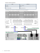
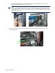
DC Power Cable Connections Cable Connection Blue Wire -48V connection Black Wire Return Green / Yellow Stripe Rack ground bus bar The breaker panel connections are displayed in the following diagram.
Installing the Breaker in the Breaker Panel CAUTION: For safety purposes, a breaker must be switched to the OFF position when inserted and removed. To install a breaker into the breaker panel, follow these steps: 1. Ensure the breaker is in the OFF position before inserting it into the breaker panel. 2. Install the breaker in the correct orientation, with the breaker handle to the right and the OFF position toward the bottom. 3. Install the two breaker screws.
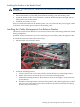
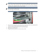
e. Install and lightly tighten the two M5 screws into the mounting bracket. You will properly torque these screws at a later point. NOTE: The mounting bracket needs to be torqued tight at a certain angle to hold its retainer bracket flush with the CMA. That is why you first install the retainer bracket with lightly tightened screws, position it in place over the CMA, and then tightly torque all the screws in place. 3.
IMPORTANT: Each retainer bracket needs to match the sag of each CMA and remain flush with its CMA in order to properly hold it in place during earthquakes. Otherwise the CMA can slip out from under the retainer and swing freely in the rear of the cabinet, damaging itself and other components in the rear of the cabinet. NOTE: Due to the sag of the CMA from the cable weight, there might be a gap between the CMA and the retainer bracket. To close the gap, press the retainer bracket down onto the CMA. 4. 5. 6.
*AH410-9002A* Printed in the US