Configuring Arrays on HP Smart Array Controllers Reference Guide Abstract This document identifies, and provides instructions for, the array configuration tools available for HP ProLiant controller and server products. This document is for the person who installs, administers, and troubleshoots servers and storage systems. HP assumes you are qualified in the servicing of computer equipment and trained in recognizing hazards in products with hazardous energy levels.
© Copyright 2006, 2013 Hewlett-Packard Development Company, L.P. The information contained herein is subject to change without notice. The only warranties for HP products and services are set forth in the express warranty statements accompanying such products and services. Nothing herein should be construed as constituting an additional warranty. HP shall not be liable for technical or editorial errors or omissions contained herein. Confidential computer software.
Contents Overview of array configuration tools ............................................................................................. 5 Utilities available for configuring an array ...................................................................................................... 5 Comparison of the utilities ............................................................................................................................. 5 Support for standard configuration tasks ......................
Setting up ADU Remote Service Mode .......................................................................................................... 95 Launching the utility in CLI mode .................................................................................................................. 95 Launching the utility in GUI mode................................................................................................................. 95 Diagnostic report procedures ....................................
Overview of array configuration tools Utilities available for configuring an array To configure an array on an HP Smart Array controller, three utilities are available: • HP Array Configuration Utility (ACU)—An advanced utility that enables you to perform many complex configuration tasks • Option ROM Configuration for Arrays (ORCA)—A simple utility used mainly to configure the first logical drive in a new server before the operating system is loaded • HP Online Array Configuration Utility for NetWare
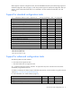
ORCA supports only basic configuration tasks, whereas CPQONLIN and ACU provide full-range support for standard configuration tasks (on page 6). ACU also provides support for advanced configuration tasks (on page 6). Some of these advanced tasks are not available in all ACU interface formats (GUI, CLI, and Scripting). Support for standard configuration tasks A "+" indicates the feature or task is supported. A "–" indicates the feature or task is not supported.
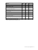
Procedure ACU GUI ACU CLI ACU Scripting Configure a RAID 60 logical drive +/– +/– +/– Copy the configuration of one system to multiple systems –1 –1 + Disable a redundant controller +2 + – Enable or disable a physical drive write cache + + + +/– – HP Drive Erase (replace the content of a physical drive or logical +/– drive with zeros or random 0 and 1) + Identify devices by causing their LEDs to flash + – Move an array (copy all array data to a new array and then delete the old arra
HP Smart Array Advanced Pack About SAAP SAAP is a collection of additional and advanced controller features embedded in the firmware of select Smart Array controllers. To access SAAP features, activate the software with a registered license key. SAAP 1.
Option ROM Configuration for Arrays About ORCA ORCA is a ROM-resident array configuration utility that executes automatically during initialization of an HP Smart Array controller.
HP Array Configuration Utility About ACU ACU is the main tool for configuring arrays on HP Smart Array controllers. It exists in three interface formats: the ACU GUI, the ACU CLI, and ACU Scripting. All formats provide support for standard configuration tasks (on page 6). ACU also provides support for advanced configuration tasks (on page 6). Some of the advanced tasks are available in only one format.
• Launching ACU from the SmartStart CD (G7 or earlier) (on page 11) • Launching ACU from an ISO image (all generations) (on page 11) To access the ACU CLI or ACU Scripting in an offline environment, you must launch ACU from an ISO image. When offline ACU launches, an Execution Mode screen does not appear, because ACU does not support Remote Service Mode in an offline environment. For this functionality, use ACU in an online environment ("Accessing ACU in the online environment" on page 15).
• Installing the image on a PXE server (on page 13) Booting from the ISO image on a drive, on a key, or through iLO provides the same GUI interface. The user can select to run Offline ACU GUI, ACU CLI, or ACU Scripting. Mounting the image on a local drive 1. Download the HP ProLiant Offline Array Configuration Utility ISO image from the HP website (http://h20000.www2.hp.com/bizsupport/TechSupport/SoftwareDescription.jsp?lang=en&cc=US &swItem=MTX-aad98a00c0d6469d8abf78e2f3&mode=4&idx=1). 2.
3. Using ISO mounting software, mount the Offline ACU ISO image to a Windows drive. For this example, use "E:." 4. Insert a USB key into a USB connector on the Windows system. For this example, use "F:." 5. Run the HP USB Key Utility. 6. At the main screen, select Next. 7. If you agree with the end user license agreement, select the Agree radio button, and then click Next. 8. Select Create a bootable USB key from CD/DVD, and then click Next. 9. At the requirements screen, click Next. 10.
Set up PXELinux Before proceeding with the configuration, ensure that your TFTP server and PXELinux configuration is set up and configured properly. To set up PXELinux: 1. Download the HP ProLiant Offline Array Configuration Utility ISO image from the HP website (http://h20000.www2.hp.com/bizsupport/TechSupport/SoftwareDescription.jsp?lang=en&cc=US &swItem=MTX-aad98a00c0d6469d8abf78e2f3&mode=4&idx=1). 2. Copy the ISO image to the network file system, and note the location.
The iso1 parameter helps the PXE-booted ACU Offline CD locate the ISO image. The iso1mnt parameter tells the PXE-booted ACUCD where the iso1 image must be mounted. Your final configuration must be similar to the following example: label sos MENU LABEL HP ProLiant Offline ACU Image kernel vmlinuz append initrd=initrd.img media=cdrom rw root=/dev/ram0 ramdisk_size=257144 init=/bin/init loglevel=3 ide=nodma ide=noraid pnpbios=off vga=791 splash=silent showopts TYPE=AUTOMATIC iso1=nfs://192.168.0.
Users familiar with the previous versions of ACU Scripting must now install the ACU CLI application to obtain the scripting executable. The new ACU scripting executable (hpacuscripting) replaces the former executable (cpqacuxe) in all scripts. For information about the minimum monitor settings and the version numbers of supported operating systems and browsers, see the README.txt file provided with the executable. To use ACU in the online environment: 1.
c. 5. Reboot the server. (Optional) To make newly created logical drives available for data storage, use the operating system disk management tools to create partitions and format the drives. Linux OS 1. From any command prompt, enter one of the following: o For local mode, enter: cpqauxe-nosmh o For remote mode, enter: cpqacuxe-R ACU launches in a browser (Mozilla Firefox). 2. For a list of options, enter the following: cpqacuxe-h Launching ACU on a local server to configure a remote server 1.
a. Click Start, and then select Programs>HP System Tools>HP Array Configuration Utility>Setup HP Array Configuration Utility. b. When the Execution Mode screen appears, select Local Application Mode. c. 8. Reboot the server. (Optional) To make newly created logical drives available for data storage, use the operating system disk management tools to create partitions and format the drives. Launching ACU on a remote server to configure a local server 1.
c. 11. Reboot the server. (Optional) To make newly created logical drives available for data storage, in a Windows OS, use the operating system disk management tools to create partitions and format the drives. Using the ACU GUI Access ACU with one of the many methods available: • Accessing ACU in the offline environment (on page 10) • Accessing ACU in the online environment (on page 15) When you launch the ACU GUI, the application opens and ACU scans the system and detects controllers.
In previous versions of ACU, this process was called the Standard Configuration mode. For more information, see "Configuration screen (on page 20)." o Diagnostics/SmartSSD—This screen displays a list of controllers and options for generating, viewing, and saving diagnostic reports for those controllers. In previous versions, this tab and screen were called Diagnostics. For more information, see "Diagnostics/SmartSSD screen (on page 22).
When a device is selected, the following elements appear: • • • System Status—This panel, at left, provides the following information and functionality: o Date and time stamps for the status o A Refresh button to refresh the status o Status icons (critical, warning, and informational) with the number of individual alerts for each category o A View Status Alert link that displays device-specific alerts on the right side of the screen Systems And Devices—This panel, at left, provides the following
o Options and information pertinent to the task, after a task is selected For a list of possible tasks that are available on the Configuration screen, see "Configuration tasks (on page 28)." Diagnostics/SmartSSD screen To access this screen, click the Diagnostics/SmartSSD tab.
The Diagnostics/SmartSSD screen provides a list of controllers and options related to generating and viewing diagnostic reports. Tasks are selectable from this screen. Additional tasks are available upon clicking Run Array Diagnostics Reports.
o • Check boxes for individual controllers or all controllers Available Tasks—This panel, at right, provides the following information and functionality: o Tasks that are available for the selected device based on its current status and configuration HP Array Configuration Utility 24
o Options and information pertinent to the task, after a task is selected For a list of possible tasks that are available on the Diagnostics/SmartSSD screen, see "Diagnostics tasks (on page 39)." Wizards screen To access this screen, click the Wizards tab.
The Wizards screen displays the GUI elements from the Welcome screen and provides status, more detailed information, and available wizards or options for the selected device.
o A Show menu that toggles between Logical View and Physical View In this example, the Systems And Devices information continues past the edge of the panel. To view all of the information, use the horizontal scroll bar or use the mouse to widen the panel.
o Options and information pertinent to the wizard, after a wizard is selected For a list of possible wizards that are available on the Wizards screen, see "Wizards (on page 41)." ACU help The Help button, at upper right, opens the embedded ACU help file.
For certain tasks, the controller must have SAAP activated by a registered license key. For more information, see "About SAAP (on page 8)." When a controller or device is selected, the tasks that appear are a subset of the total number of possible tasks for the selected item. ACU lists or omits tasks based on the controller model and configuration. For example, if the selected controller has no unassigned physical drives, Create Array is not an available task.
†If performed with a Gen8 controller, this task requires a registered HP SmartCache license key. Configuring a controller 1. Open ACU. For more information, see "Using the ACU GUI (on page 19)." 2. Select a controller from the Controller/Device menu. The Configuration screen appears. 3. Configure the controller: o To configure manually, see "Performing a Configuration task (on page 30)." o To configure with a wizard, see "Using Wizards (on page 42)" or "Using Express Configuration (on page 44).
The System Status, Systems And Devices, and Available Tasks panels appear. The listed tasks are available for this device in its current configuration. For more information, see "Configuration tasks (on page 28)." 3. Click a task button.
A list of all possible options for that task appears on the right side of the screen, replacing the task list. 4. Select the settings or configuration options for the device. 5. Use the Next and Back buttons to navigate multiple screens of options. 6. Click Save or OK. Rapid Parity Initialization When you create a logical drive, you must initialize the parity using Rapid Parity Initialization.
If ACU is already open, click the Configuration tab. 2. Select a controller from the Controller/Device menu. The System Status, Systems And Devices, and Available Tasks panels appear. 3. Select Create a logical drive. 4. Make selections for Fault Tolerance, Strip Size, Sectors/Track, Size, and Caching. 5. Under Parity Initialization Method, select either Default or Rapid. 6. Click Save.
Changing the Spare Activation Mode The spare activation mode feature enables the controller firmware to activate a spare drive under the following conditions: • When a data drive reports a predictive failure (SMART) status • When a data drive fails; this mode is the default. In normal operations, and for older controllers, the firmware starts rebuilding a spare drive only when a data drive fails.
5. Click Save. About HP SmartCache HP SmartCache enables solid state drives to be used as caching devices for hard drive media. Data can be accessed from the solid state drive instead of hard drives. HP SmartCache provides the following features: • Accelerates application performance • Provides lower latency for transactions in applications • Supports all operating systems, without the need for changes To support HP SmartCache, the Smart Array Controller firmware must be 3.42 or later.
3. Click Enable HP SmartCache. 4. Select a solid state drive type. 5. Select one or more physical drives from the list of available drives. 6. Click Save. Some features may not be available with HP SmartCache enabled. 7. With the SmartCache selected in the left panel, click Create SmartCache for Logical Drive. 8. Select the logical drive to cache. 9. Select the size of the cache. HP recommends 10% of the drive size, and it must be a minimum of 1 GiB. 10. Click Save.
Splitting a mirrored array 1. Run the ACU GUI in offline mode. See "Accessing ACU in an offline environment ("Accessing ACU in the offline environment" on page 10)." 2. At the Configuration screen, select the appropriate controller from the Controller/Device menu. 3. From the Systems and Devices tree, select the appropriate array. 4. In the Available Tasks panel, click Split Mirrored Array. 5. Click OK. 6.
2. At the Configuration screen, select the appropriate controller from the Controller/Device menu. 3. From the Systems and Devices tree, select the appropriate array. 4. In the Available Tasks panel, click Create Split Mirror Backup. A verification and message dialog box appears. 5. Click OK. ACU creates the array according to the following rules: 6. o If the original array contained RAID 1 or RAID 1+0 drives, then the primary array will contain RAID 0 drives.
Healing an array The Heal Array operation enables you to enter a command to replace failed physical drives in the array with healthy physical drives. After replacement, the original array and logical drive numbering is unaffected. To use Heal Array, you must meet the following conditions: • The array has at least one failed drive. • The array is not transforming (for example, rebuilding to a spare). • The array has a working cache, making it capable of transformation.
This report contains information about all devices, such as array controllers, storage enclosures, drive cages, as well as logical, physical, and tape drives. For supported solid state drives, this report also contains SmartSSD Wear Gauge information. • SmartSSD Wear Gauge report This report contains information about the current usage level and remaining expected lifetime of solid state drives attached to the system. • Serial output logs This log details the serial output for the selected controller.
o Generate SmartSSD Wear Gauge Report o Run Array Diagnostic Reports For this example, use the diagnostic reports selection. 2. Select Run Array Diagnostic Reports. The array diagnostic report screen appears. 3. Select a device or devices from the Report Contents panel. The Available Tasks panel appears. For more information, see "Diagnostics tasks (on page 39)." 4.
For certain tasks, the controller must have SAAP activated by a registered license key. For more information, see "About SAAP (on page 8)." When a controller is selected, the wizards that appear are a subset of the total number of wizards that are possible for the selected controller. ACU lists or omits wizards based on the controller model and configuration. For example, if the selected controller has no unassigned physical drives, Expand Array is not an available wizard.
The System Status, Systems And Devices, and Available Wizards panels appear. The listed wizards are available for this device in its current configuration. For more information, see "Wizards (on page 41)." 3. Click a wizard button.
A list of all possible options for that wizard appears on the right side of the screen, replacing the wizard list. 4. Select the settings or configuration options for the device. 5. Use the Next and Back buttons to navigate multiple screens of options. 6. Click Save or OK. Using Express Configuration Express Configuration is a wizard that creates the optimum number of arrays and logical drives from all of the physical drives that are attached to the controller.
ACU displays possible logical drive configurations based on groupings of drives with the same capacity. 4. For each logical drive, select a RAID Type. ACU identifies possible RAID configurations and lists spare drive capability, the size of the logical drive, fault tolerance, and write performance. 5. Click Next. The wizard configures the arrays and logical drives. 6. When the configuration is complete, click Finish.
You can make an isolated change of just one configuration parameter on one device. For VMware ESXi 5.0, ACU CLI works similarly to the Command mode mentioned. However, slight differences exist, requiring you to run ACU CLI through the VMware vSphere esxcli command-line utility. For more information about using HP ACU CLI for ESXi 5.0, see ACU CLI release notes or the HP website (ftp://ftp.hp.com/pub/softlib2/software1/pubsw-linux/p414707558/v68034/hpacucli-9.0-24.0.noarc h.txt).
The variable This variable provides the path to the device that you want to configure. The device can be a controller, an array, a logical drive, or a physical drive. The syntax used is as follows: controller all | slot=# | wwn=# | chassisname="AAA" | serialnumber=# | chassisserialnumber=# | [array=all|] [logicaldrive all|#] [physicaldrive all|allunassigned|[#:]#:#,[#:]#:#...
8 16 (current value) 32 64 128 (default) 256 To determine which parameters can be queried, use the help feature of the CLI ("The help command" on page 51). Hiding warning prompts When you enter a command for an operation that can potentially destroy user data, the CLI displays a warning and prompts you for input (a y or an n) before continuing the operation. This situation is undesirable when running batch file scripts. To prevent warning prompts from being displayed, use the term forced as a parameter.
Keyword Abbreviation in ACU Keyword CLI Abbreviation in ACU CLI licensekey lk tapedrive td logicaldrive ld waitforcacheroom wfcr mnpdelay mnpd — — *The CLI also uses this keyword and abbreviation for the terms box name and RAID array ID. The show command The show command enables you to obtain information about a device.
Accelerator Ratio: 10% Read / 90% Write Drive Write Cache: Disabled Total Cache Size: 1024 MB Total Cache Memory Available: 816 MB No-Battery Write Cache: Disabled Cache Backup Power Source: Capacitors Battery/Capacitor Count: 1 Battery/Capacitor Status: OK SATA NCQ Supported: True Spare Activation Mode: Activate on drive failure Controller Temperature (C): 40 Cache Module Temperature (C): 0 Capacitor Temperature Boot Controller: True (C): 0 Primary Boot Volume: logicaldrive 1 Secondary Boot Volume
physical physicaldrive 1:11 (box 1:bay 11, Parallel SCSI, 9.1 GB, OK) Displaying the current versions of the application layers The version command displays the current versions of the application and other software layers. Syntax: version Example command: version A typical output would be: ACU CLI Version: 9.10.16.0 SoulAPI Version: 6.0.15.0 InfoManager Version: 6.1.14.
Setting the boot volume This procedure is only available in the offline environment. The boot volume is the volume that contains the OS and its support files. To work properly, the boot volume must be accessible by the designated boot controller. See "Setting the boot controller (on page 51)." Syntax: modify [bootvolume=primary|secondary|none] where is a controller and a logical drive.
=> => => => => set target ctrl slot=3 array A add drives=1:7,1:8,1:9 array B add spares=1:10,1:11 ctrl slot=4 ld 3 modify ss=64 modify rp=high This sequence includes a command for a different target (the controller in slot 4) as a demonstration. Note that the next command in the sequence (the one for modifying the rebuild priority) applies to the controller in slot 3, not the one in slot 4.
• [ssdrpt=on|off] specifies to generate or not generate the Smart SSD Wear Gauge report. The default is off. • [xml=on|off] outputs diagnostic information in formatted XML. The off value is provided for backward compatibility and is ignored. • [zip=on|off] compresses the output to a zipped file. Default behavior is uncompressed. The off value is provided for backward compatibility and is ignored. Example commands: ctrl all diag file=c:\allcontrollers.zip ctrl slot=4 diag file=c:\ctrl_slot4.
=> ctrl slot=4 add lk=9876543210222224444466666 Optimizing controller performance for video On some controller models, you can optimize the controller performance for video. To use this features on an HP Smart Array G6 or G7 controller, a registered SAAP ("About SAAP" on page 8) license key is required. Syntax: modify dpo=enable elevatorsort=disable irp=enable queuedepth=automatic mnpd=60 where the target is any valid controller.
Parameter Acceptable values Comments size #|min|max|maxmbr|? sectors 32|63|default|? This parameter determines the desired size of the logical drive. Units are MB.* The default setting is max. aa enable|disable|? drivetype The default setting depends on the operating system. sas|satalogical|sata|saslogical|par allelscsi|ss_sas|ss_sata|? The default setting is enable. — *Use only these units. Do not enter any extra text in the command to specify the units.
=> ctrl ch="Lab 4" pd all show In this case, the screen response is: MSA1000 at Lab 4 array A physicaldrive 1:12 (box 1:bay12, Parallel SCSI, 36.4 GB, OK) unassigned physicaldrive 1:13 (box 1:bay13, Parallel SCSI, 9.1 GB, OK) physicaldrive 1:14 (box 1:bay14, Parallel SCSI, 9.1 GB, OK) The second array is to be created on the two remaining physical drives.
When moving the logical drive, you can choose one of the following destinations: • An existing array • A new array you create To move a logical drive to an existing array, use the following information. Syntax: modify [newarray=] Command examples: ctrl slot=1 ld 3 modify newarray=C ctrl slot=1 ld 3 modify newarray=? // shows the available arrays To move a logical drive and create a new array, use the following information. Syntax: modify [drives=[#: ]#:#,[#: ]#:#,[#: ]#:#–[#: ]#:#,.
Viewing SSD physical drives The ssdphysicaldrive keyword is a valid target for the show command, and it outputs the solid state physical drives on the specified controller. Syntax: ssdpd all show [detail] where the target is any valid controller. Example commands: controller slot=5 ssdpd all show controller slot=5 ssdpd all show detail Viewing SSD information The ssdinfo keyword provides a summary for solid state drives for the specified controller.
Rapid Parity Initialization is available only for supported controllers and in arrays composed of supported physical drives.
• When a data drive fails; this mode is the default. In normal operations, and for older controllers, the firmware starts rebuilding a spare drive only when a data drive fails. With the predictive failure activation mode, rebuilding can begin before the drive fails, reducing the likelihood of data loss that could occur if an additional drive fails. Use the spareactivationmode keyword to toggle the spare activation mode for the controller between drive failure and drive predictive failure.
Shrinking an array Some controllers may not support this option or may require a license key to enable this feature. You can shrink the size of an array by removing a drive from an existing array. Observe the following criteria: • After the shrink, the array must have sufficient capacity to contain all of the configured logical volumes. • You may not remove drives from the array if the resulting number of drives does not support the fault tolerance (RAID level) of any existing logical drive.
drives by specifying the new destination drives in the command (1e:1:12-1e:1:14). To maintain the same spare drive, be sure to designate the spare drive for the moved array. Example commands: => array a modify drives=1e:1:12-1e:1:14 spares=1e:1:9 => array b modify drives=1c:1:6-1c:1:7 Replacing an array Some controllers may not support this option or may require a license key to enable this feature. You can replace an array by designating different physical drives for the array.
If the operating system does not support logical drive extension, carrying out this command makes data on the logical drive unavailable. Therefore, the CLI displays a warning prompt as a safeguard in case you are using such an operating system. To prevent the prompt from appearing, use the forced parameter.
modify [preferredpathmode=automatic|manual|?] where is a redundant controller. Example command: controller ch="lab 3" modify ppm=manual Assigning a redundant controller to a logical drive When you have set the preferred path mode ("Setting the preferred path mode" on page 64) in a redundant system to Manual, you must use the chassisslot command to assign each logical drive in the system to one of the redundant controllers.
=> ctrl slot=3 modify rp=high Changing the Expand Priority setting The Expand Priority setting determines the urgency with which the controller treats an internal command to expand an array. • At the low setting level, normal system operations take priority over an array expansion. • At the medium setting, expansion occurs for half of the time, and normal system operations occur for the rest of the time. • At the high setting, the expansion takes precedence over all other system operations.
Syntax: modify reenable [forced] Example command: => ctrl slot=3 ld 1 modify reenable forced Changing the controller cache ratio The controller cache ratio setting determines the amount of memory allocated to read and write operations. Different types of applications have different optimum settings. You can change the ratio only if the controller has a battery-backed cache (because only battery-backed cache can be used for write cache) and if there are logical drives configured on the controller.
Enabling a script to exit on error When a script encounters an error during execution, the exitonerror keyword enables the script to decide whether to continue or to exit the application and return an exit code.
FILENAME is the name of the ACU input file, and ext is the file extension. If you do not specify the name and location of this file, ACU searches for ACUINPUT.ini in the ACU working directory. The -internal and -external switches limit configuration operations to internal or external controllers. The -reset flag destroys any existing data and overwrites the current configuration with the configuration specified in the script. The -e switch information is used only if ACU must generate an error file.
ReadCache = 0|10|20|25|30|40|50|60|70|75|80|90|100 WriteCache = 0|10|20|25|30|40|50|60|70|75|80|90|100 RebuildPriority = Low|Medium|High ExpandPriority = Low|Medium|High SurfaceScanDelay = N PreferredPathMode = Auto|Manual ; COMMENT: the following five entries are used to optimize the controller performance for video MNPDelay = 0|1|2|...|60 ; units are minutes, zero indicates disabled IRPEnable = Yes|No DPOEnable = Yes|No ElevatorSortEnable = Yes|No QueueDepth = 2|4|8|16|32|Auto Array = A|B|C|D|E|F|G|..
• Control category (on page 72) • Controller category (on page 72) • Array category (on page 76) • Logical Drive category (on page 78) • HBA category (on page 83) Each category has several scripting options, but you do not always need to assign values to every option. ACU can use default values in some instances, while in other instances, a listed option might not be relevant for a particular configuration or scripting mode.
Category Options Logical Drive ArrayAccelerator LogicalDrive NumberOfParityGroups PreferredPath RAID Renumber Repeat ResourceVolumeOwner Sectors ShrinkSize Size SizeBlocks StripSize StripeSize ConnectionName HBA HBA_WW_ID HostMode Description These options describe a logical drive that is to be configured on an array that was previously specified in the script. (If no array was previously specified, ACU stops processing the script and creates an error file.
• ClearConfigurationWithDataLoss (on page 74) • DeleteLicenseKey ("LicenseKey, DeleteLicenseKey" on page 74) • DPOEnable ("Video performance options" on page 75) • DriveWriteCache (on page 74) • ElevatorSortEnable ("Video performance options" on page 75) • ExpandPriority ("RebuildPriority, ExpandPriority" on page 75) • IRPEnable ("Video performance options" on page 75) • LicenseKey ("LicenseKey, DeleteLicenseKey" on page 74) • MNPDelay ("Video performance options" on page 75) • NoBatteryW
You can use this option to prevent stale cache issues. ClearConfigurationWithDataLoss Clearing the configuration causes data loss because it deletes all logical volumes and arrays on the controller. If you clear a configuration, you can write commands later in the script file to create a new configuration from the liberated drive capacity. The values for this option are Yes or No. The default value is No.
The quotes enclosing the string are optional. The quotes allow you to use leading space characters in the RaidArrayId. ReadCache, WriteCache Enter a number between 0 and 100 to specify the percentage of cache that is to be allocated to drive reads or writes. The default value for both options is 50, unless the controller firmware supplies a specific default read/write ratio. The allowable cache ratios depend on the controller model and whether it has battery-backed write cache.
• Set the QueueDepth to one of the following values: 2|4|8|16|32|Automatic Array category The Array category has the following options: • Array (on page 76) • CachingArray (on page 76) • Drive (on page 76) • DriveType (on page 77) • Join (on page 77) • OnlineSpareMode (on page 77) • OnlineSpare (on page 78) • Split (on page 78) Array Enter a letter or pair of letters to identify the array that is to be created or reconfigured, and observe these additional limitations: • In Configure mod
• If the value of the ClearConfigurationWithDataLoss (on page 74) option is Yes, you can use the Drive option to remove drives from an array. Determine which mode to use: • Auto method mode—ACU configures all the available drives on the controller into one array. If the drives are of different capacities, ACU determines the capacity of the smallest drive and uses the same amount of space on all other available drives.
For controllers that support Auto Replace Drive, setting this value to AutoReplace enables a rebuilt spare drive to become a data drive in the array. When the failed data drive is replaced, it assumes the role of the former spare, eliminating the need for a second array rebuild. Behavior Description Dedicated Default value for spares AutoReplace The spare drive becomes a data drive when the rebuild is complete.
• RAID (on page 80) • Renumber (on page 80) • Repeat (on page 81) • ResourceVolumeOwner (on page 81) • Sectors (on page 81) • ShrinkSize (on page 81) • Size (on page 81) • SizeBlocks (on page 82) • StripeSize (on page 82) • StripSize (on page 82) ArrayAccelerator This option specifies whether the array accelerator is enabled or disabled for the specified logical drive. The default value is Enabled.
The maximum number of parity groups possible for a particular number of physical drives is the total number of drives divided by the minimum number of drives necessary for that RAID level (three for RAID 50, four for RAID 60). PreferredPath If you select the Manual setting for PreferredPathMode (on page 74), use the PreferredPath command to specify the path for I/O to the logical drive on a redundant controller in active/active mode. The default setting for this option is 1.
Typically used after a Join command, this option ensures the proper logical volume numbering is set, for example, the boot volume is ID 1. Do not mix Renumber and Join operations in the same script, because ACU Scripting does not update its internal state after a renumber. If other commands are mixed with Renumber, commands targeting specific volumes might target the incorrect volume.
In Reconfigure mode, the default setting is the existing size of the logical drive. If you enter a larger value, ACU extends the logical drive to the new size if there is unused drive capacity on the same array, as long as the operating system supports logical drive extension. You cannot reduce the size of the logical drive. CAUTION: Back up all data before extending a logical drive. SizeBlocks This option specifies the size of the logical drive in 512-byte blocks.
• 512—512 KB • 1024—1024 KB (supported starting with Gen8 controllers) The default strip size value depends on the action mode: • In Configure action mode, the default value is determined by the RAID level that you specified earlier in the script. • In Reconfigure action mode, the default value for this option is the strip size that is already configured for the logical drive.
XML support ACU scripting v8.30 and later support an XML file format for input and output. XML output To create an XML output document, use an XML suffix with the output file name: C:\hpacuscripting -c out.xml The following text is an example XML output file. Configure Custom 1I:4:6, 2I:2:4, 2I:2:3, 2I:2:2 No 5 52478 32 64 Enabled 5 52478 32 64
Standard format XML format Action= Configure Method= Custom Configure Custom Controller= Slot 1 Array=A Drive= 1I:4:8, 1I:4:7 LogicalDrive= 1 RAID= 0 Size= 100000 1I:4:8, 1I:4:7 0 100000
Error code Error message Comment or clarification successfully. 2053 Too many coinciding expansion, migration, The new configuration requires more or extension operations transformations than are possible at one time. For example, you cannot expand a logical volume and transform its RAID level at the same time. 2056 Controller does not support license keys The controller does not support license key entry or deletion. 2059 Invalid license key The entered license key is not a valid license key.
Error code Error message Comment or clarification 2836 New Logical Drive ID does not match the next available logical drive ID. If you are attempting to replicate a configuration that has non-consecutive logical drive numbers, then you must change the script file so that the logical drive numbers are consecutive. The script file specifies a logical drive ID that is not the first unused ID in the sequence.
Error code Error message Comment or clarification slot for an available, active controller, or the controller is not available. 2866 Failure opening capture file — 2867 Failure opening input file — 2868 Failure opening error file — 2877 There are no suitable spares available ACU found no drives that could be used as spares for the specified array. 2880 Invalid Physical Disk Type Specified — 2882 Invalid MNP delay The specified value for MNP delay is invalid.
Error code Error message Comment or clarification 3023 The connectionname cannot be removed — when the hostmode has a non-default value. Invalid Host Mode — 3024 Invalid Adapter ID — 3025 This controller does not have host mode modification capability — 3026 — 3029 You need to have administrator rights to continue. Another instance of ACU is already running (possibly a service). Please terminate the ACU application before running ACU scripting. Invalid Drive Cache setting.
HP Array Diagnostics and SmartSSD Wear Gauge Utility About the utility Formerly known as the Array Diagnostics Utility, the HP Array Diagnostics and SmartSSD Wear Gauge Utility collects all possible information about storage devices in the system, detects all problems, and provides a detailed configuration report in .zip format. After downloading and installing the software, you can run the utility as a GUI or a CLI in an online environment.
o Interface o WWID o Drive model o Serial number o Firmware revision o Total blocks The SmartSSD Wear Gauge report contains information on the current usage level of and expected lifetime remaining for solid state drives attached to the system.
Field Description SSD Wear Status Indicates the SSD's wear status with one of the following messages: • • • • • • • • • OK Not Supported The SmartSSD Wear Gauge log is full. Wear Gauge parameters are not available. SSD has less than 5% usage remaining before wearout. SSD has less than 2% usage remaining before wearout. SSD has less than an estimated 56 days before it reaches the maximum usage limit for writes (wearout) and should be replaced as soon as possible.
Setting up ADU Remote Service Mode You can run ADU as a Windows Service, so that it starts automatically and runs in the background at all times. ACU is accessible remotely from the System Management Homepage (https://localhost:2381). To set up the service: 1. Click Start>All Programs>HP System Tools>HP Array Diagnostics and SmartSSD Wear Gauge Utility>Setup ADU Remote Mode. 2. Select Enable Remote Service Mode. 3. Click OK. Launching the utility in CLI mode 1. Open a command prompt. 2.
The splash screen appears. 2. Select one of the following tasks: o Viewing the diagnostic report (on page 96) o Generating the diagnostic report (on page 98) o Viewing the SmartSSD Wear Gauge report (on page 99) o Generating the SmartSSD Wear Gauge report (on page 100) For more information about the interface, select Help. Diagnostic report procedures Viewing the diagnostic report 1. Launch the GUI ("Launching the utility in GUI mode" on page 95). 2. Select View Diagnostic Report.
The utility generates and displays the report. The diagnostic report includes an additional RIS Event Log tab. Smart Array controllers store configuration data in the RAID information sector of all physical drives. The RIS Event Log reads the data and displays the decoded change logs.
3. Click RIS Event Log. The log appears. 4. After reviewing the report, do one of the following: o Click Save Report, and then save the generated file. o Click ADU Home, and then perform additional tasks. o Click Exit ADU. Generating the diagnostic report 1. Launch the GUI ("Launching the utility in GUI mode" on page 95). 2. Select Generate Diagnostic Report.
The utility generates the report, and then displays the File Download dialog box. 3. Open or save the file. 4. When you are finished with the file, do one of the following: o Click Save Report, and then save the generated file. o Click ADU Home, and then perform additional tasks. o Click Exit ADU. Identifying and viewing diagnostic report files The diagnostic report output archive contains the following files: • ADUReport.txt—Diagnostic report in text format • ADUReport.
The utility generates and displays the report. 3. After reviewing the report, do one of the following: o Click Save Report, and then save the generated file. o Click ADU Home, and then perform additional tasks. o Click Exit ADU. Generating the SmartSSD Wear Gauge report 1. Launch the GUI ("Launching the utility in GUI mode" on page 95). 2. Select Generate SmartSSD Wear Gauge Report. The utility generates the report, and then displays the File Download dialog box.
3. Open or save the file. 4. After reviewing the report, do one of the following: o Click Save Report, and then save the generated file. o Click ADU Home, and then perform additional tasks. o Click Exit ADU. Identifying and viewing SmartSSD Wear Gauge report files The SmartSSD Wear Gauge report output archive contains the following files: • SmartSSDWearGaugeReport.txt—SmartSSD wear gauge report in text format • SmartSSDWearGaugeReport.
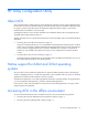
Drive arrays and fault-tolerance methods Drive arrays The capacity and performance of a single physical (hard) drive is adequate for home users. However, business users demand higher storage capacities, higher data transfer rates, and greater protection against data loss when drives fail. Connecting extra physical drives (Pn in the figure) to a system increases the total storage capacity but has no effect on the efficiency of read/write (R/W) operations.
With an array controller installed in the system, the capacity of several physical drives can be combined into one or more virtual units called logical drives (also called logical volumes and denoted by Ln in the figures in this section). Then, the read/write heads of all the constituent physical drives are active simultaneously, reducing the total time required for data transfer.
The group of physical drives containing the logical drive is called a drive array, or just array (denoted by An in the figure). Because all the physical drives in an array are commonly configured into just one logical drive, the term array is often used as a synonym for logical drive. However, an array can contain several logical drives, each of a different size. Each logical drive in an array is distributed across all of the physical drives within the array.
• RAID 50 configurations tolerate one failed drive in each parity group. • RAID 6 configurations tolerate two failed drives at a given time. • RAID 60 configurations tolerate two failed drives in each parity group. • RAID 1 (ADM) and RAID 10 (ADM) configurations tolerate multiple drive failures if no more than two drives, mirrored to one another, fail. Fault-tolerance methods Several fault-tolerance methods exist. Those most often used with Smart Array controllers are hardware-based RAID methods.
RAID 1 and RAID 1+0 (RAID 10) In RAID 1 and RAID 1+0 (RAID 10) configurations, data is duplicated to a second drive. When the array contains only two physical drives, the fault-tolerance method is known as RAID 1. When the array has more than two physical drives, drives are mirrored in pairs, and the fault-tolerance method is known as RAID 1+0 or RAID 10. In each mirrored pair, the physical drive that is not busy answering other requests answers any read requests that are sent to the array.
Advantages: • This method has the second highest read performance of any fault-tolerant configuration. • No data is lost when a drive fails, as long as no failed drive is mirrored to another failed drive. • Up to half of the physical drives in the array can fail. Disadvantages: • This method is expensive, because many drives are needed for fault tolerance. • Only half of the total drive capacity is usable for data storage.
When the array has more than three physical drives, drives are mirrored in trios, and the fault-tolerance method is known as RAID 10 (ADM). In each mirrored trio, the physical drives that are not busy answering other requests answer any read requests that are sent to the array. This behavior is called load balancing. If a physical drive fails, the remaining two drives in the mirrored trio can still provide all the necessary data.
RAID 5—distributed data guarding In a RAID 5 configuration, data protection is provided by parity data (denoted by Px,y in the figure). This parity data is calculated stripe by stripe from the user data that is written to all other blocks within that stripe. The blocks of parity data are distributed evenly over every physical drive within the logical drive.
RAID 6 (ADG), like RAID 5, generates and stores parity information to protect against data loss caused by drive failure. With RAID 6 (ADG), however, two different sets of parity data are used (denoted by Px,y and Qx,y in the figure), allowing data to still be preserved if two drives fail. Each set of parity data uses a capacity equivalent to that of one of the constituent drives. This method is most useful when data loss is unacceptable but cost is also an important factor.
RAID 50 RAID 50 is a nested RAID method in which the constituent hard drives are organized into several identical RAID 5 logical drive sets (parity groups). The smallest possible RAID 50 configuration has six drives organized into two parity groups of three drives each. For any given number of hard drives, data loss is least likely to occur when the drives are arranged into the configuration that has the largest possible number of parity groups.
RAID 60 RAID 60 is a nested RAID method in which the constituent hard drives are organized into several identical RAID 6 logical drive sets (parity groups). The smallest possible RAID 60 configuration has eight drives organized into two parity groups of four drives each. For any given number of hard drives, data loss is least likely to occur when the drives are arranged into the configuration that has the largest possible number of parity groups.
Item RAID 0 RAID 1+0 RAID 5 RAID 6 (ADG) RAID 1(0) (ADM) Alternative name Striping (no fault tolerance) Mirroring Distributed Data Guarding Advanced Data Guarding Advanced Data Mirroring n/2 n-1 n-2 n/3 50% 67% to 93% 50% to 96% 33% 2 3 4 3 Yes Yes Yes Yes Yes Only if no three drives are in the same mirror group High High Formula for number of drives usable n for data (n = total number of drives in array) 100% Percentage of drive space usable* Minimum number of physical drive
Neither of these alternative fault-tolerance methods supports online spares or automatic data recovery, nor do they support auto-reliability monitoring or interim data recovery. If you decide to use one of these alternative methods, configure your arrays with RAID 0 for maximum storage capacity and refer to your operating system documentation for further implementation details.
Diagnosing array problems Diagnostic tools To troubleshoot array problems and generate feedback about arrays, use the following diagnostic tools: • ACU For more recent products, array diagnostics is available with ACU v8.28.13.0 and later. This utility is available on the SmartStart CD in the controller kit and also on the HP website (http://www.hp.com/support). For more information about ACU, see "About ACU (on page 10).
problem-specific flowcharts to help you navigate complex troubleshooting processes. To view the guide, select a language: • English (http://www.hp.com/support/ProLiant_TSG_en) • French (http://www.hp.com/support/ProLiant_TSG_fr) • Italian (http://www.hp.com/support/ProLiant_TSG_it) • Spanish (http://www.hp.com/support/ProLiant_TSG_sp) • German (http://www.hp.com/support/ProLiant_TSG_gr) • Dutch (http://www.hp.com/support/ProLiant_TSG_nl) • Japanese (http://www.hp.
Acronyms and abbreviations ACU Array Configuration Utility ADG Advanced Data Guarding (also known as RAID 6) ADM Advanced Data Mirroring ADU Array Diagnostics Utility CPQONLIN NetWare Online Array Configuration Utility DHCP Dynamic Host Configuration Protocol HBA host bus adapter ORCA Option ROM Configuration for Arrays POST Power-On Self Test RBSU ROM-Based Setup Utility RIS reserve information sector SAAP Smart Array Advanced Pack Acronyms and abbreviations 117
SAS serial attached SCSI SATA serial ATA SSD solid-state drive SSP Selective Storage Presentation TFTP Trivial File Transfer Protocol WBEM Web-Based Enterprise Management WWN World Wide Name Acronyms and abbreviations 118
Documentation feedback HP is committed to providing documentation that meets your needs. To help us improve the documentation, send any errors, suggestions, or comments to Documentation Feedback (mailto:docsfeedback@hp.com). Include the document title and part number, version number, or the URL when submitting your feedback.
Index A C action mode, ACU scripting 72 ACU (Array Configuration Utility) 10 ACU GUI, methods for opening 19 ACU GUI, procedure overview 30 ACU help 28 ACU scripting 72, 76, 83 additional information 114 ADG (advanced data guarding) 109 ADU (Array Diagnostic Utility) 114 ADU Remote Service Mode 95 advanced configuration tasks, support for 6 advanced data guarding (ADG) 109 array accelerator, enabling or disabling, ACU CLI 67 array category options, ACU scripting 76 array concepts 102 array configuration u
device information, obtaining 49 devices, discovering 19 devices, identifying 53 diagnostic report 39, 40, 53, 96, 98, 99 diagnostic tools 114 diagnostics 22, 39, 40, 53 Diagnostics screen 22 Diagnostics tasks 39, 40 disabling drive cache 67 disabling the array accelerator, ACU CLI 67 disabling the array accelerator, ACU scripting 79 disabling the redundant controller 65 distributed data guarding 108 DPOEnable 75 drive array concepts 102 drive cache, enabling or disabling 67, 74 drive information 58, 59 dri
logical drive, moving, ACU CLI 57 logical drive, specifying, ACU scripting 79 LogicalDrive 79 M MaxBoot setting 81 menu options, ACU GUI 30, 42 method mode, ACU scripting 72 methods for opening the ACU GUI 19 migrating stripe size or RAID level, ACU CLI 64 migrating stripe size or RAID level, ACU GUI 30 migrating stripe size or RAID level, ACU scripting 80, 82 mirrored arrays 36 mirrored drives 106, 107 MNPDelay 75 mounting virtual media 12, 13 moving an array 62, 76 N navigating the interface 19 nested R
S sample script 69 screen description 19, 20, 22, 25, 28 script files 69 scripting modes 68 scripting options 70 scripting syntax 69 Sectors 81 selecting a RAID level 112 shorthand in CLI 48 show (CLI command) 49 shrinking an array 30, 62, 76 ShrinkSize 81 Size 81 SizeBlocks 82 Smart Array Advanced Pack (SAAP) 8 SmartSSD Wear Gauge report 40, 99, 100, 101 SmartStart CD as source of ACU 11 software-based RAID 112 spare activation mode 60 spare drives, ACU CLI 60 spare drives, ACU GUI 30, 42 spare drives, ACU