HP ProLiant DL785 Server User Guide User Guide HP Part Number: AH233-9003B Published: September 2009 Edition: 3
© Copyright 2008–2009 Hewlett-Packard Development Company, L.P. The information contained herein is subject to change without notice. The only warranties for HP products and services are set forth in the express warranty statements accompanying such products and services. Nothing herein should be construed as constituting an additional warranty. HP shall not be liable for technical or editorial errors or omissions contained herein. Microsoft, Windows, and Windows NT are U.S.
Table of Contents 1 Component identification...............................................................................................7 Front panel components.........................................................................................................................7 Front panel LEDs and buttons................................................................................................................9 System Insight Display LEDs.........................................................
Removing the processor memory cell and airflow baffle...............................................................39 Installing a processor.......................................................................................................................41 Memory options....................................................................................................................................46 Advanced ECC memory.................................................................................
Drivers.............................................................................................................................................68 ProLiant Support Packs...................................................................................................................69 Operating system version support..................................................................................................69 Change control and proactive notification...............................................
Server specifications..............................................................................................................................95 11 Technical support........................................................................................................97 Before you contact HP...........................................................................................................................97 HP contact information.................................................................
1 Component identification In this section • “Front panel components” (page 7) • “Front panel LEDs and buttons” (page 9) • “System Insight Display LEDs” (page 10) • “SAS and SATA hard drive LEDs” (page 12) • “SAS and SATA hard drive LED combinations” (page 12) • “Processor memory cell components” (page 13) • “Rear panel components” (page 14) • “Rear panel LEDs and buttons” (page 15) • “Power supply LED” (page 16) • “Internal components” (page 16) • “SPI board components” (page 18) • “System maintenance swit
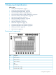
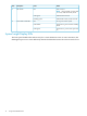
Item Description 8 Hard drive bay 3 right 9 Hard drive bay 4 right 10 Hard drive bay 5 right 11 Hard drive bay 6 right 12 Hard drive bay 7 right 13 Hard drive bay 8 right not shown Hard drive bay 1 left (optional) not shown Hard drive bay 2 left (optional) not shown Hard drive bay 3 left (optional) not shown Hard drive bay 4 left (optional) not shown Hard drive bay 5 left (optional) not shown Hard drive bay 6 left (optional) not shown Hard drive bay 7 left (optional) not shown Hard drive bay 8
Front panel LEDs and buttons Item Description Color Status 1 UID button and LED Off UID button is not activated Solid blue UID button is activated for server identification Flashing blue Server is being remotely managed Off Normal (system is off or in standby mode) Solid green Normal (system is powered on) Flashing amber Redundant power supply failure (system power supply is no longer redundant) Flashing red Critical power supply failure Off Normal (system is off or in standby mode) S
Item Description Color Status 5 NIC 2 LED Off NIC not used NOTE: Rear panel NIC can show link or activity while in standby mode. 6 Power button and LED Solid green Linked to the network Flashing green Linked with activity on the network Off No ac power to the system Solid amber System has ac power and is in standby mode Solid green System has ac power and is powered on System Insight Display LEDs The front panel health LEDs indicate only the current hardware status.
system attributes. The System Insight Display LEDs identify components experiencing an error, event, or failure. CAUTION: Do not block airflow by pushing the SID flush against the server while it is in the down position. IMPORTANT: When removing the access panel to view the Systems Insight Display LEDs, leave the server powered on. The Systems Insight Display LEDs are cleared when the server is powered off.
LED Component PROCESSOR/MEMORY BOARD X Processor PROC X PROCESSOR/MEMORY BOARD X Processor DIMM board BOARD X SAS and SATA hard drive LEDs Item Description Color Status 1 Fault/UID LED Amber Drive failure Flashing amber Fault-process activity Blue Unit identification is active Off No fault-process activity Green Drive activity Flashing green High activity on the drive or the drive is being configured as part of an array Off No drive activity 2 Online/activity LED SAS and SATA hard
Online/activity LED Fault/UID LED (green) (amber/blue) Interpretation On Off The drive is online, but is not currently active. Flashing (1 Hz) Flashing amber (1Hz) Flashing (1 Hz) Off Flashing irregularly Flashing amber (1Hz) The drive is active, but a predictive failure alert has been received for this drive. Replace the drive as soon as possible. Flashing irregularly Off The drive is active and is operating normally.
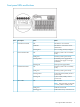
Item Description 6 DIMM slot 6C 7 DIMM slot 7D 8 DIMM slot 8D 9 Processor socket Rear panel components 14 Item Description 1 NIC connector 1 2 Keyboard connector 3 USB connector 4 Video connector 5 Serial connector 6 iLO 2 connector 7 Mouse connector 8 NIC connector 2 9 Power supply 1 10 Power supply 2 11 Power supply 3 12 Redundant power supply 4 (optional) 13 Redundant power supply 5 (optional) 14 Redundant power supply 6 (optional) 15 PCI Express or HTx expansio
Item Description 18 Fan 5 19 Fan 6 Rear panel LEDs and buttons Item Description LED Color Status 1 UID Solid blue Activated Flashing blue Server remotely managed Off Deactivated Green Linked to network Off Not linked to network Green (solid or flashing) Network activity Off No network activity 2 3 LAN Link LED LAN Activity LED Rear panel LEDs and buttons 15
Power supply LED Color Status Off No ac power Blinking green ac power; standby power on Solid green Full power on; normal operation Blinking amber Power supply failure Internal components 16 Item Description 1 Media module 2 Fan 3 3 Fan 2 Component identification
Item Description 4 Fan 1 5 System maintenance switch SW6 6 System maintenance switch SW1 7 SPI Board 8 PCI Express x8 non-hot-plug expansion slot 11 9 PCI Express x16 non-hot-plug expansion slot 10 10 PCI Express x8 non-hot-plug expansion slot 9 11 PCI Express x16 non-hot-plug expansion slot 8 12 PCI Express x4 non-hot-plug expansion slot 7 13 PCI Express x4 non-hot-plug expansion slot 6 14 PCI Express x16 non-hot-plug expansion slot 5 15 PCI Express x4 non-hot-plug expansion slot 4
Combo PCIe/HTx I/O backplane Item Description 3 Blank slot 4 HyperTransport non-hot-plug expansion slot 8 5 PCI Express x4 non-hot-plug expansion slot 7 6 PCI Express x4 non-hot-plug expansion slot 6 7 PCI Express x16 non-hot-plug expansion slot 5 8 PCI Express x4 non-hot-plug expansion slot 4 9 PCI Express x4 non-hot-plug expansion slot 3 10 PCI Express x4 non-hot-plug expansion slot 2 11 PCI Express x8 non-hot-plug expansion slot 1 SPI board components SPI (core I/O) board Item Descr
Position Description Switch Function 2 Configuration lock Off System configuration can be changed On System configuration is locked 3 Reserved — Reserved 4 Reserved — Reserved 5 Password protection override Off Password is enabled On Password is disabled Off Switch has no function On ROM reads system configuration as invalid 6 Reset configuration 7 POST LED switch 1 8 POST LED switch 2 See Table 1-1 (page 19) for details.
System maintenance switch (SW1) CAUTION: All supported AMD Opteron quad-core processors 3.1 GHz or greater and all supported AMD Opteron six-core processors require the system maintenance switch, located on the I/O backplane, (SW1) position 5 to be in the On position. HP recommends updating to the latest version of firmware. Earlier firmware versions might not validate the required switch setting for these processors.
Table 1-2 Battery health and BBWC status LED patterns (continued) LED 3 pattern LED 4 pattern Interpretation Flashing (1 Hz) The battery pack is below the minimum charge level and is being charged. Features that require a battery (such as write cache, capacity expansion, stripe size migration, and RAID migration) are temporarily unavailable until charging is complete. The recharge process takes between 15 minutes and two hours, depending on the initial capacity of the battery.
Item Description 1 Fan 1 2 Fan 2 3 Fan 3 4 Fan 4 5 Fan 5 6 Fan 6 Component identification
2 Setup In this section • “Optional installation services” (page 23) • “Rack planning resources” (page 23) • “Optimum environment” (page 24) • “Rack warning and cautions” (page 26) • “Electrical grounding requirements” (page 27) • “Identifying rack server shipping carton contents” (page 28) • “Installing hardware options” (page 28) • “Installing the server into the rack” (page 28) • “Installing the cable management arm” (page 28) • “Powering on and configuring the server” (page 28) • “Installing the operati
If you intend to deploy and configure multiple servers in a single rack, refer to the white paper on highdensity deployment at the HP website (http://www.hp.com/products/servers/platforms). Optimum environment When installing the server, select a location that meets the environmental standards described in this section.
The maximum recommended ambient operating temperature (TMRA) for most server products is 35°C (95°F). CAUTION: Follow these guidelines to reduce the risk of damage to the equipment when installing third-party options: • Do not permit optional equipment to impede airflow around the server or to increase the internal rack temperature beyond the maximum allowable limits. • Do not exceed the manufacturer’s TMRA.
For electrical power ratings on options, refer to the product rating label or the user documentation supplied with that option. WARNING! To reduce the risk of personal injury, fire, or damage to the equipment, do not overload the ac supply branch circuit that provides power to the rack. Consult the electrical authority with jurisdiction over wiring and installation requirements of your facility.
WARNING! To reduce the risk of personal injury or damage to the equipment, be sure of the following: • The leveling jacks are extended to the floor. • The full weight of the rack rests on the leveling jacks. • The stabilizing feet are attached to the rack if it is a single-rack installation. • The racks are coupled together in multiple-rack installations. • Extend only one component at a time. A rack can become unstable if more than one component is extended for any reason.
national electrical wiring codes, such as the International Electrotechnical Commission (IEC) Code 364, parts 1 through 7. Furthermore, you must be sure that all power distribution devices used in the installation, such as branch wiring and receptacles, are listed or certified grounding-type devices.
Installing the operating system To operate properly, the server must have a supported operating system. For the latest information on supported operating systems, refer to the HP website (http://www.hp.com/go/supportos). Two methods are available to install an operating system on the server: SmartStart assisted installation Insert the SmartStart CD into the CD drive and reboot the server. Manual installation Insert the operating system CD into the CD drive and reboot the server.
3 Operations In this section • “Power up the server” (page 31) • “Power down the server” (page 31) • “Extending the server from the rack” (page 31) • “Removing the access panel” (page 32) • “Accessing the System Insight Display” (page 33) • “Hot-plug fans” (page 34) • “Removing the system battery” (page 37) Power up the server To power up the server, press the Power On/Standby button.
NOTE: The release latches lock into place when the rails are fully extended. WARNING! To reduce the risk of personal injury or equipment damage, be sure that the rack is adequately stabilized before extending a component from the rack. WARNING! To reduce the risk of personal injury, be careful when pressing the server rail release latches and sliding the server into the rack. The sliding rails could pinch your fingers. 3.
NOTE: The T-15 Torx screwdriver is shipped with the server and can be located on the rear panel (“Rear panel components” (page 14)). 3. Lift up on the hood latch and remove the access panel. 4. After installing hardware options, replace the access panel. Be sure that the panel is securely locked into place before powering up the server. Accessing the System Insight Display IMPORTANT: When viewing the Systems Insight Display LEDs (“System Insight Display LEDs” (page 10)), leave the server powered on.
2. Flip down the SID for easier viewing. CAUTION: Do not block airflow by pushing the SID flush against the server while it is in the down position. Hot-plug fans The server supports redundant hot-plug fans, each with two individual fans rotors, in a 5+1 configuration to provide proper airflow to the server. The airflow strategy contains two thermal zones with three fan units in the bottom zone (accessed from the server rear), and three fan units in the upper zone (accessed internally).
4. Pull the fan straight up and out of the chassis. IMPORTANT: Remove and replace one fan at a time. If the system detects two fan failures, the server shuts down to avoid thermal damage. 5. Install a new hot-plug fan. CAUTION: To prevent server components from overheating, replace the fan within 20 seconds. Failure to observe this caution results in the server automatically shutting down to prevent an overtemperature condition. NOTE: 6. 7.
5. Pull the fan straight up and out of the chassis. IMPORTANT: Remove and replace one fan at a time. If the system detects two fan failures, the server shuts down to avoid thermal damage. 6. Install a new hot-plug fan. CAUTION: To prevent server components from overheating, replace a fan within 20 seconds. Failure to observe this caution results in the server automatically shutting down to prevent an overtemperature condition. NOTE: 7.
Removing the system battery If the server no longer automatically displays the correct date and time, you may need to replace the battery that provides power to the real-time clock. Under normal use, battery life is 5 to 10 years. WARNING! The computer contains an internal lithium manganese dioxide, a vanadium pentoxide, or an alkaline battery pack. A risk of fire and burns exists if the battery pack is not properly handled. To reduce the risk of personal injury: • Do not attempt to recharge the battery.
4 Hardware options installations In this section • “Introduction” (page 39) • “Processor options” (page 39) • “Memory options” (page 46) • “Hard drive guidelines” (page 47) • “Installing DVD or CD drive” (page 48) • “Hot-plug power supplies” (page 49) • “Expansion boards” (page 51) • “Battery-backed write cache” (page 53) Introduction If you plan to install more than one hardware option, read the installation instructions for all the hardware options and identify similar steps to streamline the installatio
CAUTION: When working with the processor memory cell always place the component on a flat, level, antistatic surface. 5. 40 Press the two airflow baffle release tabs, pivot the airflow baffle up, and remove the airflow baffle.
Installing a processor To install a processor: WARNING! To reduce the risk of personal injury from hot surfaces, allow the heatsink to cool before touching it. 1. Open the heatsink retaining bracket. 2. 3. Remove the heatsink. Open the processor retaining latch and the processor socket retaining bracket.
4. 42 Align the processor installation tool with the socket and install the processor.
CAUTION: The processor is designed to fit only one way into the socket. Use the alignment guides on the processor and socket to properly align the processor with the socket. 5. Press down firmly until the processor installation tool clicks and separates from the processor, then remove the processor installation tool.
6. 44 Close the processor retaining latch and the processor socket retaining bracket.
7. 8. 9. Clean the old thermal grease from the heatsink with the alcohol swab. Allow the alcohol to evaporate before continuing. Apply all the grease to the top of the processor in one of the following patterns to ensure even distribution. Install the heatsink. 10. Close the heatsink retaining bracket. 11. Replace the processor memory airflow baffle.
12. Install the processor memory cell into the server. 13. Power up the server. Memory options Each processor memory cell can hold two to eight DIMMs. At least one pair of DIMMs must be installed in slots 1A and 2A on each processor memory cell to operate the server.
5. Install the DIMM. Hard drive guidelines When adding hard drives to the server, observe the following guidelines: • The system automatically sets all device numbers. • If only one hard drive is used, install it in the bay with the lowest device number. • Hard drives must be SFF types. • Drives must have the same capacity to provide the greatest storage space efficiency when drives are grouped together into the same drive array. • The server supports up to eight SAS or SATA hot-plug hard drives.
2. 3. 4. Install the hard drive into the server. Be sure that the hard drive seats firmly into the connector in the back of the drive cage. Close the ejector lever. Determine the status of the hard drive from the hot-plug hard drive LEDs, see “SAS and SATA hard drive LEDs” (page 12) and “SAS and SATA hard drive LED combinations” (page 12). Installing DVD or CD drive The server is shipped with one DVD drive. You can install an optional DVD drive or CD drive. To remove a DVD, CD drive or blank: 1.
4. Remove the media module. a. Disconnect all cabling from the media module. b. Press the media module release latch. c. 5. 6. Pull the media module away from the server. Lift the DVD release tab on the left side of the media module and push the drive out from the rear. Install the media drive into the server. CAUTION: To prevent improper cooling and thermal damage, do not operate the server unless all bays are populated with either a component or a blank.
2. Install the power supply. 3. 4. 5. 6. Connect the power cord to the power supply. Secure the power cords to the retaining clip. Connect the power cord to the power source. Be sure that the power supply LED is green.
7. Be sure that the front panel external health LED is green. IMPORTANT: For maximum server availability, be sure that the primary and redundant power supplies are powered by separate ac power sources. NOTE: If the server will be shipped to another location after configuration, install a shipping screw into each power supply.
Combo PCIe/HTx I/O backplane Item Description 1 Blank slot 2 HyperTransport non-hot-plug expansion slot 9 3 Blank slot 4 HyperTransport non-hot-plug expansion slot 8 5 PCI Express x4 non-hot-plug expansion slot 7 6 PCI Express x4 non-hot-plug expansion slot 6 7 PCI Express x16 non-hot-plug expansion slot 5 8 PCI Express x4 non-hot-plug expansion slot 4 9 PCI Express x4 non-hot-plug expansion slot 3 10 PCI Express x4 non-hot-plug expansion slot 2 11 PCI Express x8 non-hot-plug expansio
4. Push and hold the spring-loaded latch to the side of the server, and lift up on the hinge. 5. 6. Unlock the retaining clip (for full-length expansion boards). Install the expansion board. 7. 8. 9. 10. 11. Lock the retaining clip (for full-length expansion boards) and close the latch. Connect any required internal or external cables to the expansion board. Replace the access panel (“Removing the access panel” (page 32)). Slide the server into the rack.
Along with the cache module, the battery pack provides transportable data protection, increases overall controller performance, and maintains any cached data for up to 72 hours after the server loses power. The NiMH batteries in the battery pack are continuously recharged by a trickle-charging process whenever the system power is on.
6. Install the new cache on the controller. Press firmly above each connector to ensure good electrical contact. IMPORTANT: 7. If the cache is not properly connected, the controller can not boot. Replace the controller in the server.
8. Install the battery, if applicable. a. Install the battery pack into the server. b. Plug the battery cable (supplied in the battery pack kit) into the battery pack. c. Route the cable and connect it to the cache module. NOTE: After installing a battery pack, you might see a POST message during reboot indicating that the array accelerator (cache) is temporarily disabled. This is normal, because the new battery pack probably has a low charge.
5 Cabling In this section • “Cabling overview” (page 57) • “BBWC cabling” (page 57) • “SAS and SATA hard drive cabling” (page 58) • “SAS expander cabling” (page 58) • “High power graphics card cabling” (page 60) Cabling overview This section provides guidelines that help you make informed decisions about cabling the server and hardware options to optimize performance. For information on cabling peripheral components, refer to the white paper on high-density deployment at the HP website (http://www.hp.
SAS and SATA hard drive cabling CAUTION: When routing cables, always be sure that the cables are not in a position where they can be pinched or crimped. SAS expander cabling To install a SAS expander: 1. 2. 3. 4. 5. 58 Cabling Power down the server (“Power down the server” (page 31)). Extend or remove the server from the rack (“Extending the server from the rack” (page 31) ). Remove the access panel (“Removing the access panel” (page 32)).
6. 7. Install together the Smart Array Controller into slot 1 and the SAS expander into slot 2 (“Expansion boards” (page 51)). Route and connect the cables from the SAS expander to the SAS backplanes.
TIP: For best cable management route the cable to SAS backplane 1 under the power cable at the power supply backplane and the cable to SAS backplane 2 under other cables in the center cable routing channel. High power graphics card cabling IMPORTANT: Install high powered graphics cards in PCIe 16x slots for optimum performance. The server can power a maximum of four auxiliary high powered graphics card power connections.
6 Software and configuration utilities In this section • “Configuration tools” (page 61) • “HP ProLiant Essentials Rapid Deployment Pack” (page 63) • “Option ROM Configuration for Arrays” (page 64) • “Array Configuration Utility” (page 64) • “Re-entering the server serial number and product ID” (page 64) • “Management tools” (page 65) • “Diagnostic tools” (page 67) • “Remote support and analysis tools” (page 68) • “Keeping the system current” (page 68) Configuration tools SmartStart software SmartStart is
For more information, and to download the SmartStart Scripting Toolkit, refer to the HP website (http://www.hp.com/servers/sstoolkit).
NOTE: The server may not support all the following examples. NOTE: If the boot drive is not empty or has been written to in the past, ORCA does not automatically configure the array. You must run ORCA to configure the array settings. Drives installed Drives used RAID level 1 1 RAID 0 2 2 RAID 1 3, 4, 5, or 6 3, 4, 5, or 6 RAID 5 More than 6 0 None To change any ORCA default settings and override the auto-configuration process, press the F8 key when prompted.
Option ROM Configuration for Arrays Before installing an operating system, you can use the ORCA utility to create the first logical drive, assign RAID levels, and establish online spare configurations.
10. Press the F10 key to confirm exiting RBSU. The server will automatically reboot. Management tools Automatic Server Recovery ASR is a feature that causes the system to restart when a catastrophic operating system error occurs, such as a blue screen, ABEND, or panic. A system fail-safe timer, the ASR timer, starts when the System Management driver, also known as the Health Driver, is loaded. When the operating system is functioning properly, the system periodically resets the timer.
HP Systems Insight Manager HP SIM is a web-based application that allows system administrators to accomplish normal administrative tasks from any remote location, using a web browser. HP SIM provides device management capabilities that consolidate and integrate management data from HP and third-party devices. IMPORTANT: You must install and use HP SIM to benefit from the Pre-Failure Warranty for processors, SAS and SCSI hard drives, and memory modules.
• Works offline and online • Supports Microsoft®Windows NT®, Windows® 2000, Windows Server™ 2003, Novell Netware, and Linux operating systems IMPORTANT: This utility supports operating systems that may not be supported by the server. For operating systems supported by the server, refer to the HP website (http://www.hp.com/support).
• • • From within HP SIM (“HP Systems Insight Manager” (page 66)) From within Survey Utility From within operating system-specific IML viewers — For NetWare: IML Viewer — — • • For Windows®: IML Viewer For Linux: IML Viewer Application From within the iLO 2 user interface From within HP Insight Diagnostics (“HP Insight Diagnostics” (page 67)) For more information, refer to the Management CD in the HP ProLiant Essentials Foundation Pack.
IMPORTANT: Always perform a backup before installing or updating device drivers. ProLiant Support Packs PSPs represent operating system-specific bundles of ProLiant optimized drivers, utilities, and management agents. Refer to the PSP website (http://h18000.www1.hp.com/products/servers/management/psp.html). Operating system version support Refer to the operating system support matrix (http://www.hp.com/go/supportos).
7 Troubleshooting In this section • “Troubleshooting resources” (page 71) • “Pre-diagnostic steps” (page 71) • “Loose connections” (page 74) • “Service notifications” (page 75) • “Server power-on problems flowchart” (page 75) • “Troubleshooting flowcharts” (page 76) • “POST error messages and beep codes” (page 86) Troubleshooting resources The HP ProLiant Servers Troubleshooting Guide provides simple procedures for resolving common problems as well as a comprehensive course of action for fault isolation an
Symbols on equipment The following symbols may be placed on equipment to indicate the presence of potentially hazardous conditions. This symbol indicates the presence of hazardous energy circuits or electric shock hazards. Refer all servicing to qualified personnel. WARNING! To reduce the risk of injury from electric shock hazards, do not open this enclosure. Refer all maintenance, upgrades, and servicing to qualified personnel. This symbol indicates the presence of electric shock hazards.
WARNING! Only authorized technicians trained by HP should attempt to repair this equipment. All troubleshooting and repair procedures are detailed to allow only subassembly/module-level repair. Because of the complexity of the individual boards and subassemblies, no one should attempt to make repairs at the component level or to make modifications to any printed wiring board. Improper repairs can create a safety hazard.
• • • Run HP Insight Diagnostics (“HP Insight Diagnostics” (page 67)) and use the survey page to view the current configuration or to compare it to previous configurations. Refer to your hardware and software records for information. Refer to server LEDs and their statuses. Prepare the server for diagnosis 1. 2. 3. 4. 5. 6. Be sure the server is in the proper operating environment with adequate power, air conditioning, and humidity control.
Service notifications To view the latest service notifications, refer to the HP website (http://www.hp.com/go/bizsupport). Select the appropriate server model, and then click the Troubleshoot a Problem link on the product page. Server power-on problems flowchart Symptoms: • The server does not power on. • The system power LED (“System Insight Display LEDs” (page 10)) is off or amber. • The external health LED (“System Insight Display LEDs” (page 10)) is red or amber.
Troubleshooting flowcharts To effectively troubleshoot a problem, HP recommends that you start with the first flowchart in this section, “Start diagnosis flowchart” (page 77)and follow the appropriate diagnostic path. If the other flowcharts do not provide a troubleshooting solution, follow the diagnostic steps in “General diagnosis flowchart” (page 77).
Start diagnosis flowchart Item Refer to 1 “General diagnosis flowchart” (page 77) 2 “Server power-on problems flowchart” (page 79) 3 “POST problems flowchart” (page 81) 4 “OS boot problems flowchart” (page 82) 5 “Server fault indications flowchart” (page 84) General diagnosis flowchart The General diagnosis flowchart provides a generic approach to troubleshooting. If you are unsure of the problem, or if the other flowcharts do not fix the problem, use the following flowchart.
Item Refer to 4 The most recent version of a particular server or option firmware is available on the following websites: • HP Support website (http://www.hp.com/support) • HP ROM-BIOS/Firmware Updates website (http://h18023.www1.hp.com/support/files/ server/us/romflash.html) 5 "General memory problems are occurring" in the HP ProLiant Servers Troubleshooting Guide located on the Documentation CD or on the HP website (http://www.hp.
Server power-on problems flowchart Symptoms • • The server does not power on. • The system power LED (“System Insight Display LEDs” (page 10)) is off or amber. • The external health LED (“System Insight Display LEDs” (page 10)) is red or amber. • The internal health LED (“System Insight Display LEDs” (page 10)) is red or amber. NOTE: For the location of server LEDs and information on their statuses, refer to the server documentation.
• • 80 Improperly seated component or interlock problem (“System Insight Display LEDs” (page 10)) Faulty internal component Item Refer to 1 Chapter 1 (page 7) 2 “HP Insight Diagnostics” (page 67)or in the HP ProLiant Servers Troubleshooting Guide located on the Documentation CD or on the HP website (http://www.hp.com/support) 3 “Loose connections” (page 74) 4 Server maintenance and service guide, located on the Documentation CD, or the HP website (http:// www.hp.
POST problems flowchart Symptoms: • Server does not complete POST NOTE: • The server has completed POST when the system attempts to access the boot device. Server completes POST with error Possible problems: • Improperly seated or faulty internal component • Faulty KVM device • Faulty video device Item Refer to 1 “POST error messages and beep codes” (page 86) 2 "Video problems" in the HP ProLiant Servers Troubleshooting Guide located on the Documentation CD or on the HP website (http://www.hp.
Item Refer to 6 Server maintenance and service guide, located on the Documentation CD or the HP website (http:// www.hp.com/products/servers/platforms) 7 "Port 85 and iLO messages" in the HP ProLiant Servers Troubleshooting Guide located on the Documentation CD or on the HP website (http://www.hp.com/support) 8 "General memory problems are occurring" in the HP ProLiant Servers Troubleshooting Guide located on the Documentation CD or on the HP website (http://www.hp.
Possible causes: • Corrupted operating system • Hard drive subsystem problem • Incorrect boot order setting in RBSU Item Refer to 1 HP ROM-Based Setup Utility User Guide (http://www.hp.com/servers/smartstart) 2 “POST problems flowchart” (page 81) 3 • "Hard drive problems" in the HP ProLiant Servers Troubleshooting Guide located on the Documentation CD or on the HP website (http://www.hp.
Server fault indications flowchart Symptoms: • Server boots, but a fault event is reported by Insight “Management Agents” (page 65) • Server boots, but the internal health LED, external health LED, or component health LED is red or amber NOTE: For the location of server LEDs and information on their statuses, refer to the server documentation.
• • Redundancy failure System overtemperature condition Item Refer to 1 “Management Agents” (page 65) or in the HP ProLiant Servers Troubleshooting Guide located on the Documentation CD or on the HP website (http://www.hp.com/support) 2 • “Integrated Management Log” (page 67) or in the HP ProLiant Servers Troubleshooting Guide located on the Documentation CD or on the HP website (http://www.hp.
POST error messages and beep codes For a complete listing of error messages, refer to the "POST error messages and beep codes" in the HP ProLiant Servers Troubleshooting Guide located on the Documentation CD or on the HP website (http://www.hp.com/support). WARNING! To avoid potential problems, ALWAYS read the warnings and cautionary information in the server documentation before removing, replacing, reseating, or modifying system components.
8 Regulatory compliance notices In this section • “Regulatory compliance identification numbers” (page 87) • “Federal Communications Commission notice” (page 87) • “Declaration of conformity for products marked with the FCC logo, United States only” (page 88) • “Modifications” (page 88) • “Cables” (page 88) • “Canadian notice (Avis Canadien)” (page 89) • “European Union regulatory notice” (page 89) • “Disposal of waste equipment by users in private household in the European Union” (page 89) • “Japanese noti
equipment generates, uses, and can radiate radio frequency energy and, if not installed and used in accordance with the instructions, may cause harmful interference to radio communications. Operation of this equipment in a residential area is likely to cause harmful interference, in which case the user will be required to correct the interference at personal expense.
Canadian notice (Avis Canadien) Class A equipment This Class A digital apparatus meets all requirements of the Canadian Interference-Causing Equipment Regulations. Cet appareil numérique de la classe A respecte toutes les exigences du Règlement sur le matériel brouilleur du Canada. Class B equipment This Class B digital apparatus meets all requirements of the Canadian Interference-Causing Equipment Regulations.
Japanese notice BSMI notice Korean notice Class A equipment Class B equipment 90 Regulatory compliance notices
Laser compliance This product may be provided with an optical storage device (that is, CD or DVD drive) and/or fiber optic transceiver. Each of these devices contains a laser that is classified as a Class 1 Laser Product in accordance with US FDA regulations and the IEC 60825-1. The product does not emit hazardous laser radiation. Each laser product complies with 21 CFR 1040.10 and 1040.11 except for deviations pursuant to Laser Notice No. 50, dated May 27, 2001; and with IEC 60825-1:1993/A2:2001.
Power cord statement for Japan 92 Regulatory compliance notices
9 Electrostatic discharge In this section • “Preventing electrostatic discharge” (page 93) • “Grounding methods to prevent electrostatic discharge” (page 93) Preventing electrostatic discharge To prevent damaging the system, be aware of the precautions you need to follow when setting up the system or handling parts. A discharge of static electricity from a finger or other conductor may damage system boards or other static-sensitive devices. This type of damage may reduce the life expectancy of the device.
10 Specifications In this section • “Environmental specification” (page 95) • “Server specifications” (page 95) Environmental specification Specification Value Temperature range Operating 10°C to 35°C (50°F to 95°F)1 Non-operating -30°C to 60°C (-22°F to 140°F)2 Maximum wet bulb temperature 28°C (82.4°F) 3 Relative humidity (noncondensing) Operating 10% to 90% relative humidity (Rh), 28°C (82.4°F) maximum wet bulb temperature, non-condensing. Non-operating 5% to 95% relative humidity (Rh), 38.
Specification Value Rated input frequency 47- 63 Hz 47- 63 Hz Rated input current 24A at100 V ac 14A at 200 V ac Rated input power 2400 W 2800 W BTUs per hour 8189 9554 Power supply output Low line High line3 Power supply output 800 W per P.S.U. at 3 P.S.U. active 1200 W per P.S.U. at 3 P.S.U. active Acoustic Noise4 Idle LWAd 7.6 B LpAm 58 dBa Operating LWAd 7.
11 Technical support In this section • “Before you contact HP” (page 97) • “HP contact information” (page 97) • “Customer Self Repair” (page 97) Before you contact HP Be sure to have the following information available before you call HP: • Technical support registration number (if applicable) • Product serial number • Product model name and number • Applicable error messages • Add-on boards or hardware • Third-party hardware or software • Operating system type and revision level HP contact information Fo
NOTE: Some HP parts are not designed for customer self repair. In order to satisfy the customer warranty, HP requires that an authorized service provider replace the part. These parts are identified as "No" in the Illustrated Parts Catalog. Based on availability and where geography permits, CSR parts will be shipped for next business day delivery. Same day or four-hour delivery may be offered at an additional charge where geography permits.
Riparazione da parte del cliente Per abbreviare i tempi di riparazione e garantire una maggiore flessibilità nella sostituzione di parti difettose, i prodotti HP sono realizzati con numerosi componenti che possono essere riparati direttamente dal cliente (CSR, Customer Self Repair). Se in fase di diagnostica HP (o un centro di servizi o di assistenza HP) identifica il guasto come riparabile mediante un ricambio CSR, HP lo spedirà direttamente al cliente per la sostituzione.
Support Center anrufen und sich von einem Mitarbeiter per Telefon helfen lassen. Den Materialien, die mit einem CSR-Ersatzteil geliefert werden, können Sie entnehmen, ob das defekte Teil an HP zurückgeschickt werden muss. Wenn es erforderlich ist, das defekte Teil an HP zurückzuschicken, müssen Sie dies innerhalb eines vorgegebenen Zeitraums tun, in der Regel innerhalb von fünf (5) Geschäftstagen.
een CSR-onderdeel, verzendt HP dat onderdeel rechtstreeks naar u, zodat u het defecte onderdeel daarmee kunt vervangen. Er zijn twee categorieën CSR-onderdelen: • Verplicht: Onderdelen waarvoor reparatie door de klant verplicht is. Als u HP verzoekt deze onderdelen voor u te vervangen, worden u voor deze service reiskosten en arbeidsloon in rekening gebracht. • Optioneel: Onderdelen waarvoor reparatie door de klant optioneel is. Ook deze onderdelen zijn ontworpen voor reparatie door de klant.
com a documentação correspondente no material de transporte fornecido. Caso não o faça, a HP poderá cobrar a reposição. Para as peças de reparo feito pelo cliente, a HP paga todas as despesas de transporte e de devolução da peça e determina a transportadora/serviço postal a ser utilizado. • Para obter mais informações sobre o programa de reparo feito pelo cliente da HP, entre em contato com o fornecedor de serviços local. Para o programa norte-americano, visite o site da HP (http://www.hp.
Customer Self Repair 103
A Acronyms and abbreviations ABEND ACU ADU AMD ASR BBWR BIOS CSA CSR DIMM DOS ESD HTx IEC iLO 2 IML ISEE KVM NEMA NFPA NIC NiMH NVRAM ORCA OS PCI-X PCIe PDU POST PPM PSP RAID RBSU RDP RILOE II ROM SAS SCSI SFF SIM SNMP TMRA abnormal end Array Configuration Utility Array Diagnostics Utility Advanced Micro Devices Automatic Server Recovery battery-backed write cache Basic Input/Output System Canadian Standards Association Customer Self Repair dual inline memory module disk operating system electrostatic disc
UID UPS USB VCA 106 unit identification uninterruptible power system universal serial bus Version Control Agent Acronyms and abbreviations
Index A access panel removal, 32 ACU (Array Configuration Utility), 64 ADU (see Array Diagnostic Utility (ADU)) Array Configuration Utility (see AC (Array Configuration Utility)) Array Diagnostic Utility (ADU), 68 ASR (see Automatic Server Recovery (ASR)) auto-configuration process, 62 Automatic Server Recovery (ASR), 65 B battery replacement notice, 91 BBWC LED (see LED, battery pack) BIOS Serial Console, 63 boot options, 63 BSMI notice, 90 C cable management arm installation, 28 cables, 88 cabling, 57–6
power supply, 16 rear, 15 System Insight Display, 10 operating system installing, 29 operating systems, 69 optimum environment, 24–26 ORCA (Option ROM Configuration for Arrays), 62, 64 OS (see operating system) (see operating systems) specifications environmental, 95 server, 95 SPI board, 18 StorageWorks library and tape tools, 65 symbols on equipment, 72 system keeping current, 69 system battery, 37 System Insight Display, 10 access, 33 system maintenance switch SW1, 20 SW6, 18 Systems Insight Manager (s
*AH233-9003B* Printed in the US