HP ProLiant DL980 G7 Server User Guide Abstract This document is for the person who installs, administers, and troubleshoots servers and storage systems. HP assumes you are qualified in the servicing of computer equipment and trained in recognizing hazards in products with hazardous energy levels.
© Copyright 2011 Hewlett-Packard Development Company, L.P. The information contained herein is subject to change without notice. The only warranties for HP products and services are set forth in the express warranty statements accompanying such products and services. Nothing herein should be construed as constituting an additional warranty. HP shall not be liable for technical or editorial errors or omissions contained herein. Microsoft, Windows, and Windows Server are U.S.
Contents Server component identification ...................................................................................................... 7 Front panel components ................................................................................................................................ 7 Front panel LEDs .......................................................................................................................................... 8 System Insight Display LEDs ..........................
Single-, dual-, and quad-rank DIMMs ................................................................................................. 40 DIMM identification .......................................................................................................................... 41 DIMM installation guidelines ............................................................................................................. 41 Memory cartridge population guidelines.................................................
HP Systems Insight Manager ............................................................................................................. 84 Management Agents ........................................................................................................................ 84 Redundant ROM support ................................................................................................................... 84 USB support .............................................................................
BSMI notice ............................................................................................................................................. 112 Korean notice .......................................................................................................................................... 112 Chinese notice ......................................................................................................................................... 112 Vietnam compliance marking notice ......
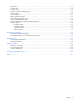
Server component identification Front panel components Item Description 1 Hard drive bay 1 2 Hard drive bay 2 3 Hard drive bay 3 4 Hard drive bay 4 5 Hard drive bay 5 6 Hard drive bay 6 7 Hard drive bay 7 8 Hard drive bay 8 9 Optical drive bay 10 UID button and LED 11 Health LED 12 NIC 1 LED 13 NIC 2 LED 14 NIC 3 LED 15 NIC 4 LED 16 Power on/Standby button and LED 17 SID 18 USB connectors 19 Video connector Server component identification 7
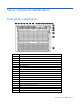
Item Description 20 Processor memory tray (upper) 21 Processor memory tray (lower) Front panel LEDs Item Description Status 1 UID button and LED Blue—Activated Blue (flashing)—Server being managed remotely Off—Deactivated 2 Health LED Green—Normal (system on) Amber (flashing)—Internal system health degraded Red (flashing)—Internal system health critical Off—Normal (system off) 3 NIC 1 LED Green—Linked to network Green (flashing)—Linked with activity on the network Off—No network connection
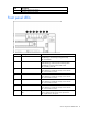
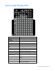
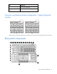
System Insight Display LEDs LED Component POWER System power EXT HEALTH External component health POWER CAP Powering capping OVER TEMP Over temperature AMP Advanced memory protection PS X Power supply FAN X Fan SPI ILK SPI board not properly seated XNC XNC board not properly seated CABLE XNC J-Link cables or management cable LOWER CPU INK Lower processor memory drawer not fully seated UPPER CPU ILK Upper processor memory drawer not fully seated PROC X Processor UPPER CPU Indica
LED Component LOWER CPU Indicates lower CPU tray with associated CPUs, memory risers and DIMMs MEMORY BOARD X DIMM 1A-8D DIMM slot Processor and memory board configuration / logical (physical) location Upper processor memory board is shown on the left. Lower processor memory board is shown on the right.
Item Description 1 Torx T-15 Tool 2 iLO 3 connector 3 Mouse connector 4 Serial connector 5 NIC connector 2 6 NIC connector 4 7 UID 8 NIC connector 3 9 NIC connector 1 10 Video connector 11 Keyboard connector 12 USB connectors 13 I/O expansion slots 14 Small form factor I/O expansion slots (optional) 15 XNC connectors 16 XNC management connector 17 Power supply 8 18 Power supply 7 19 Power supply 6 20 Power supply 5 21 Power supply 4 22 Power supply 3 23 Power s
Rear panel LEDs Item Description LED color Status 1 iLO 3 NIC Activity LED Green On or flashing—Network activity Off—No network activity 2 iLO 3 NIC Link LED Green On—Linked to network Off—Not linked to network 3 NIC 2 Activity LED Green On or flashing—Network activity Off—No network activity 4 NIC 2 Link LED Green On—Linked to network Off—Not linked to network 5 NIC 4 Activity LED Green On or flashing—Network activity Off—No network activity 6 NIC 4 Link LED Green On—Linked to n
Item Description LED color Status 9 NIC 3 Activity LED Green On or flashing—Network activity Off—No network activity 10 NIC 1 Link LED Green On—Linked to network Off—Not linked to network 11 NIC 1 Activity LED Green On or flashing—Network activity Off—No network activity Power supply LED Power LED Status Off No AC power to power supply units Green AC is present. Standby output is on, output is disabled. Green AC is present. Standby output is on, power supply DC output is on and OK.
Fan location Server component identification 14
Item Description 1 Fan 4 2 Fan 3 3 Fan 2 4 Fan 1 5 Fan module 6 6 Fan module 5 Server component identification 15
System board components Item Description 1 Optional I/O expansion board connectors: • • PCI-X/PCI Express I/O expansion board PCI Express I/O expansion board 2 Slot 7 PCIe2 x8 (4, 2, 1) 3 Slot 8 PCIe2 x8 (4, 2, 1) 4 Slot 9 PCIe2 x16 (8, 4, 2, 1) 5 Slot 10 PCIe2 x8 (4, 2, 1) 6 Slot 11 PCIe2 x8 (8, 4, 2, 1) 7 SPI board connector 8 Internal USB connectors (2) 9 NMI jumper 10 System maintenance switch 11 Optical drive connector 12 Video/USB connector 13 Solid state drive connector
System maintenance switch The system maintenance switch (SW1) is an eight-position switch that is used for system configuration. The default position for all eight positions is Off. Position Description Function S1 iLO 3 security Off = iLO 3 security is enabled. On = iLO 3 security is disabled. S2 Configuration lock Off = System configuration can be changed. On = System configuration is locked.
DIMM slot locations Each memory module contains 8 DIMM slots. The paired banks are identified by the letters A through D.
SAS hard drive LEDs Item Description 1 Fault/UID LED (amber/blue) 2 Online LED (green) SAS hard drive LED combinations Interpretation Online/activity LED (green) Fault/UID LED (amber/blue) On, off, or flashing Alternating amber and The drive has failed, or a predictive failure alert has been blue received for this drive; it also has been selected by a management application.
Online/activity LED (green) Fault/UID LED (amber/blue) Interpretation Off Steadily amber A critical fault condition has been identified for this drive, and the controller has placed it offline. Replace the drive as soon as possible. Off Amber, flashing regularly (1 Hz) A predictive failure alert has been received for this drive. Replace the drive as soon as possible. Off Off The drive is offline, a spare, or not configured as part of an array.
LED3 pattern LED4 pattern Interpretation — One blink every two seconds The system is powered down, and the cache contains data that has not yet been written to the drives. Restore system power as soon as possible to prevent data loss. Data preservation time is extended any time that 3.3 V auxiliary power is available, as indicated by LED 2. In the absence of auxiliary power, battery power alone preserves the data. A fully-charged battery can normally preserve data for at least two days.
Operations Power up the server To power up the server, press the Power On/Standby button. Power down the server WARNING: To reduce the risk of personal injury, electric shock, or damage to the equipment, remove the power cord to remove power from the server. The front panel Power On/Standby button does not completely shut off system power. Portions of the power supply and some internal circuitry remain active until AC power is removed.
2. Extend the server on the rack rails until the server rail-release latches engage. 3. After performing the installation or maintenance procedure, slide the server into the rack by pressing the server rail-release latches. Remove the access panel WARNING: To reduce the risk of personal injury from hot surfaces, allow the drives and the internal system components to cool before touching them.
CAUTION: Do not operate the server for long periods with the access panel open or removed. Operating the server in this manner results in improper airflow and improper cooling that can lead to thermal damage. To remove the component: 1. Power down the server (on page 22). 2. Extend the server from the rack (on page 22). 3. Open the locking latch, slide the access panel to the rear of the chassis, and remove the access panel.
5. Remove the processor memory drawer cover. The procedure is the same for the upper and lower processor memory drawers, and the processor memory drawer blank. CAUTION: XNC cabling (on page 74) is required for eight processor systems. Failure to cable the XNC will result in the lower processor memory drawer not being recognized by the server. Access the Systems Insight Display To access the Systems Insight Display: 1. Press and release the panel. 2.
Setup Optional installation services Delivered by experienced, certified engineers, HP Care Pack services help you keep your servers up and running with support packages tailored specifically for HP ProLiant systems. HP Care Packs let you integrate both hardware and software support into a single package. A number of service level options are available to meet your needs.
Space and airflow requirements To allow for servicing and adequate airflow, observe the following space and airflow requirements when deciding where to install a rack: • Leave a minimum clearance of 63.5 cm (25 in) in front of the rack. • Leave a minimum clearance of 76.2 cm (30 in) behind the rack. • Leave a minimum clearance of 121.9 cm (48 in) from the back of the rack to the back of another rack or row of racks.
Power requirements Installation of this equipment must comply with local and regional electrical regulations governing the installation of information technology equipment by licensed electricians. This equipment is designed to operate in installations covered by NFPA 70, 1999 Edition (National Electric Code) and NFPA-75, 1992 (code for Protection of Electronic Computer/Data Processing Equipment).
WARNING: To reduce the risk of personal injury or damage to the equipment, be sure that: • • • • • The leveling jacks are extended to the floor. The full weight of the rack rests on the leveling jacks. The stabilizing feet are attached to the rack if it is a single-rack installation. The racks are coupled together in multiple-rack installations. Only one component is extended at a time. A rack may become unstable if more than one component is extended for any reason.
To configure these utilities manually: • Press the F8 key when prompted during the array controller initialization to configure the array controller using ORCA. • Press the F9 key when prompted during the boot process to change the server settings using RBSU. The system is set up by default for the English language. For more information on the automatic configuration, refer to the HP ROM-Based Setup Utility User Guide located on the Documentation CD.
Hardware options installation Introduction If more than one option is being installed, read the installation instructions for all the hardware options and identify similar steps to streamline the installation process. WARNING: To reduce the risk of personal injury from hot surfaces, allow the drives and the internal system components to cool before touching them. CAUTION: To prevent damage to electrical components, properly ground the server before beginning any installation procedure.
Installing a processor The processors and memory are located in the drawer accessible from the front of the server. It is not necessary to extend or remove the server from the rack to install or replace processors and memory. WARNING: Use caution when installing the processor memory module or removing the processor memory module. The processor memory module is very heavy when fully populated.
5. Open the heatsink retaining bracket. 6. Open the processor retaining latch and the processor socket retaining bracket. CAUTION: Failure to completely open the processor locking lever prevents the processor from seating during installation, leading to hardware damage. 7. Open the processor locking lever and the processor socket retaining bracket. Do not remove the processor socket cover.
IMPORTANT: Be sure the processor remains inside the processor installation tool. 8. If the processor has separated from the installation tool, carefully re-insert the processor in the tool. Handle the processor by the edges only, and do not touch the bottom of the processor, especially the contact area.
9. Align the processor installation tool with the socket, and then install the processor. THE PINS ON THE SYSTEM BOARD ARE VERY FRAGILE AND EASILY DAMAGED. CAUTION: THE PINS ON THE SYSTEM BOARD ARE VERY FRAGILE AND EASILY DAMAGED. To avoid damage to the system board: • Never install or remove a processor without using the processor installation tool. • Do not touch the processor socket contacts. • Do not tilt or slide the processor when lowering the processor into the socket.
10. Press the tabs on the processor installation tool to separate it from the processor, and then remove the tool. 11. Close the processor socket retaining bracket and the processor locking lever. The processor socket cover is automatically ejected. Remove the cover. CAUTION: Be sure to close the processor socket retaining bracket before closing the processor locking lever. The lever should close without resistance.
12. Remove the heatsink protective cover. 13. Install the heatsink. 14. Close and lock the heatsink retaining bracket. 15. Install the processor memory drawer cover. 16. Install the processor memory drawer. 17. Power up the server (on page 22).
Memory options This server contains eight memory cartridge connectors in each processor memory drawer. Each memory cartridge can contain eight DIMMs, for a total of 128 DIMMs, for a maximum memory configuration of 2 TB. The server supports the following DIMM speeds: • Single- and dual-rank PC3-10600 (DDR-1333) DIMMs operating at 1066 MHz • Quad-rank PC3-8500 (DDR-1066) DIMMs operating at 1066 MHz Depending on the processor model, the memory clock speed may be reduced to 1066 or 800 MHz.
IMPORTANT: ProLiant DL980 G7 servers may be unable to provide MMIO (Memory Mapped I/O) memory to all slotted PCI devices during Power-On Self-Test (POST) in large I/O configurations, resulting in the following warning message: Warning: There is not enough available PCI memory to allocate to all devices installed in the system. Devices which were not allocated requested resources may not operate properly.
NOTE: When an HP ProLiant DL980 G7 server is configured with a DIMM that has an uninitialized SPD area, and the server is running any version of the System ROM detailed in the Scope section below, the Survey Utility in HP SmartStart will report the "Correctable Error Threshold Count" for the DIMM as "Feature Not Supported." However, this is incorrect. The DIMM does actually support "Correctable Error Threshold Count." This issue is only observed when using the Survey Tool in HP SmartStart.
DIMM identification To determine DIMM characteristics, use the label attached to the DIMM and the following illustration and table. Item Description Definition 1 Size — 2 Rank 1R = Single-rank 2R = Dual-rank 4R = Quad-rank 3 Data width x4 = 4-bit x8 = 8-bit 4 Memory speed 10600 = 1333-MHz 8500 = 1066-MHz 5 DIMM type R = RDIMM (registered) For the latest supported memory information, see the QuickSpecs on the HP website (http://www.hp.com).
• To achieve maximum performance, balance DIMM quads by letter groupings across all memory cartridges so that the (1A, 8A) pair is installed in all memory cartridges first, followed by the B-pair, C-pair, and D-pair. • When installing mixed rank DIMMs in any cartridge, DIMMs with the highest number of ranks must be installed in the white DIMM connector locations.
• Memory must be loaded in quads, with a pair of DIMMs in each memory cartridge for a corresponding processor. Upper processor memory board is shown on the left. Lower processor memory board is shown on the right. • Memory is only accessible to the system if the associated processor is installed. Do not install memory cartridges in cartridge slots without the corresponding processor installed. • Two DIMM populated memory cartridges are required per processor.
• Successive cache lines are interleaved between the DIMMs and the Lockstep SMI channels of the two memory controllers in the processor such that adjacent cache lines reside on different memory controllers, SMIs, DIMMs, and DIMM ranks for better performance. To take advantage of this feature, DIMMs should be populated evenly between all SMI channels.
• The largest contributor to maximum memory bandwidth performance is to use both memory controllers inside the processor. To achieve maximum memory bandwidth performance, populate both memory cartridges for each installed processor. This configuration is required for this server. • The second largest contributor to performance is to populate each DDR3 channel in each memory cartridge. To achieve this, the minimum DIMM count per cartridge is four DIMMs installed in DIMM pair locations A and B.
AMP modes are configured in RBSU. If the requested AMP mode is not supported by the installed DIMM configuration, the server boots in Advanced ECC mode. For more information, see "HP ROM-Based Setup Utility (on page 77)." For the latest memory configuration information, see the QuickSpecs on the HP website (http://www.hp.com/go/ProLiant). Advanced ECC memory population guidelines Advanced ECC memory is the default memory protection mode for the server.
Online Spare memory population guidelines Online spare memory provides protection against persistent DRAM failure. It monitors DIMMs for excessive correctable errors and copies the content of an unhealthy rank to an available spare rank in advance of multi-bit or persistent single-bit failures that may result in uncorrectable faults. Rank-sparing is more efficient than DIMM-sparing since only a portion of a DIMM is set aside for memory protection.
system management routine disables the failed DIMM. Further memory reads and writes will only occur on the mirrored DIMM pairs. The exceptions to Mirrored Memory mode are the following: • In Mirrored Memory mode, half of the memory is allocated to memory protection. • The available memory bandwidth is reduced by up to 50% in this mode. • Mirrored Memory mode, Online Spare mode, Hemisphere mode, and interleaving cannot be enabled simultaneously.
IMPORTANT: If all installed memory is configured for a single CPU on a ProLiant DL980 G7 server running Red Hat Enterprise Linux 5, an error message similar to the following may appear when the server is operating under a heavy workload, prior to the server becoming unresponsive: soft lockup - CPU#21 stuck for 10s! This occurs because configuring all server memory for a single CPU results in contention of all other CPUs for communication to the single node configured with memory.
6. Install the DIMM. See "Memory options (on page 38)." 7. Close the memory cartridge cover. 8. Install the memory cartridge. 9. Install the processor memory drawer cover. 10. Install the processor memory drawer. 11. Power up the server. Hot-plug hard drive option When adding hard drives to the server, observe the following general guidelines: • The system automatically sets all device numbers. • If only one hard drive is used, install it in the bay with the lowest device number.
Drives should be the same capacity to provide the greatest storage space efficiency when drives are grouped together into the same drive array. For hard drive numbers, see "Device numbers (on page 18)." To install the component: 1. Remove the hard drive blank. 2. Prepare the SAS hard drive. 3. Install the hard drive. 4. Determine the status of the hard drive from the hot-plug SAS hard drive LED combinations ("SAS hard drive LED combinations" on page 19).
Redundant hot-plug power supply option The server supports up to four hot-plug power supplies. Install all power supplies to provide full redundancy. HP recommends installing redundant hot-plug power supplies in pairs. To confirm the redundancy of your configuration, see the HP power advisor at the HP website (http://www.hp.com/go/hppoweradvisor). WARNING: To reduce the risk of electric shock or damage to the equipment: • Do not disable the power cord grounding plug.
4. Connect the power cord to the power source. 5. Be sure that the power supply LED is green ("Power supply LED" on page 13). 6. Be sure that the front panel external health LED is green ("Front panel LEDs" on page 8). Internal solid state drive expansion bay option 1. Power down the server (on page 22). 2. Extend the server from the rack (on page 22). 3. Remove the access panel (on page 23). 4. Remove the SPI board. 5. Install the solid state drive. 6. Connect the cable.
7. Install the SPI board. 8. Install the access panel. 9. Slide the server back into the rack. 10. Power up the server (on page 22). Expansion board options In the main I/O tray the server supports up to 11 expansion slots. The server ships with 5 PCI Express expansion slots.
IMPORTANT: If an HP ProLiant DL980 G7 with System ROM 2010.07.27 or a ProLiant DL580 G7 with System ROM 2010.08.28 is used with Integrated Lights-Out 3 (iLO 3) Firmware Version 1.15 (or later) and I/O cards are installed in SubIO (I/O expansion board) slots or LPIO (Low Profile PCI-e I/O expansion board) slots, then the server Power-On-Boot process may stop responding at the point where "Inlet Ambient Temperature" is displayed.
IMPORTANT: When the HP ProLiant DL980 G7 server is configured with the Low-profile PCI Express I/O expansion kit (Option Part Number AM434A) and no additional I/O backplane options are installed, I/O devices installed in the Low Profile I/O backplane may not function, causing the operating system to generate a machine check when attempting to access the devices.
IMPORTANT: ProLiant DL980 G7 servers may be unable to provide MMIO (Memory Mapped I/O) memory to all slotted PCI devices during Power-On Self-Test (POST) in large I/O configurations, resulting in the following warning message: Warning: There is not enough available PCI memory to allocate to all devices installed in the system. Devices which were not allocated requested resources may not operate properly.
IMPORTANT: On an HP ProLiant DL980 G7 server with a 128 logical CPU configuration, if an HP NC382T PCI Express Dual Port Multifunction Gigabit Server Adapter is located in any Low Profile IO slot, the network connection may drop or the NIC may stop responding. This can occur while running Windows Server 2008 R2 and HP Network Configuration Utility for Windows Server 2008 R2 Version 10.10 or Version 10.20.
4. If installed, remove the shipping screws.
5. Open the expansion board retainer, and then remove the expansion slot cover. 6. Install the expansion board. 7. Install the shipping screw, if necessary. For more information, see "Securing an expansion board for shipping." 8. Close the expansion slot retainer. 9. Connect any required internal or external cables to the expansion board. 10. Install the access panel. 11. Power up the server (on page 22). 12. Resume normal server operations.
CAUTION: To prevent improper cooling and thermal damage, do not operate the server unless all expansion slots have either an expansion slot cover or an expansion board installed. IMPORTANT: When either optional I/O expansion board in installed in a two-processor configuration, the second processor must be installed in socket 3. 1. Power down the server (on page 22). 2. Extend the server from the rack (on page 22). 3. Remove the access panel (on page 23). 4. Release the latches on the release lever.
6. Install the PCI Express I/O expansion board. 7. Install any expansion boards. 8. Slide the processor memory drawer back into the server. 9. Install the access panel. 10. Slide the server back into the rack. 11. Power up the server (on page 22). Installing the PCI-X/PCI Express I/O expansion board CAUTION: To prevent improper cooling and thermal damage, do not operate the server unless all expansion slots have either an expansion slot cover or an expansion board installed.
4. Release the latches on the release lever. 5. Lower the handle, and then extend the processor memory drawer from the server until the release latches catch.
6. Install the PCI-X/PCI Express I/O expansion board. 7. Install any expansion boards. 8. Slide the processor memory drawer back into the server. 9. Install the access panel. 10. Slide the server back into the rack. 11. Power up the server (on page 22). Low profile I/O expander 1. Power down the server (on page 22). 2. Press the release button, and open the lever.
3. Slide the I/O expander out of the server. Place a hand under the component to support it as you remove it from the server. 4. Press the side buttons to remove the component cover.
5. To open the I/O card lock, push the blue tab, flip it back, then open the hinge forward. 6. Remove expansion slot covers as necessary. To replace the component, reverse the removal procedure. Battery-backed write cache module The HP BBWC protects against hard boot, power, controller, and system board failures.
IMPORTANT: The battery pack might have a low charge when installed. In this case, a POST error message is displayed when the server is powered up, indicating that the battery pack is temporarily disabled. No action is necessary on your part. The internal circuitry automatically recharges the batteries and enables the battery pack. This process might take up to four hours. During this time, the cache module functions properly, but without the performance advantage of the battery pack.
The SPI board is not shown for clarity. 9. Install the access panel. 10. Slide the server back into the rack. 11. Power up the server (on page 22). FBWC module and capacitor pack option CAUTION: Do not use this controller with cache modules designed for other controller models, because the controller can malfunction and you can lose data. Also, do not transfer this cache module to a different controller module, because you can lose data. To install the component: 1. Back up all data. 2.
7. Install the FBWC module. 8. Connect the cable.
9. Install the capacitor pack. 10. Install the SPI board. 11. Install the access panel. 12. Slide the server back into the rack. 13. Power up the server (on page 22). HP Trusted Platform Module option Use these instructions to install and enable a TPM on a supported server. This procedure includes three sections: 1. Installing the Trusted Platform Module board (on page 71). 2. Retaining the recovery key/password (on page 71). 3. Enabling the Trusted Platform Module (on page 72).
• When returning a system board for service replacement, do not remove the TPM from the system board. When requested, HP Service provides a TPM with the spare system board. • Any attempt to remove an installed TPM from the system board breaks or disfigures the TPM security rivet. Upon locating a broken or disfigured rivet on an installed TPM, administrators should consider the system compromised and take appropriate measures to ensure the integrity of the system data.
6. Install the TPM board. Press down on the connector to seat the board ("System board components" on page 16). 7. Install the TPM security rivet by pressing the rivet firmly into the system board. 8. Install the SPI board. 9. Install the access panel. 10. Slide the server back into the rack. 11. Power up the server (on page 22). Enabling the Trusted Platform Module 1. When prompted during the start-up sequence, access RBSU by pressing the F9 key. 2.
6. Press the Esc key to exit the current menu, or press the F10 key to exit RBSU. 7. Reboot the server. 8. Enable the TPM in the OS. For OS-specific instructions, see the OS documentation. CAUTION: When a TPM is installed and enabled on the server, data access is locked if you fail to follow the proper procedures for updating the system or option firmware, replacing the system board, replacing a hard drive, or modifying OS application TPM settings.
Cabling XNC cabling CAUTION: XNC cabling (on page 74) is required for eight processor systems. Failure to cable the XNC will result in the lower processor memory drawer not being recognized by the server.
For best cable management, follow the recommend connection order. 1. Make connections labeled 1 through 8 in the illustration. 2. Refer to cabling illustrations and table to make connections 9 though 16. For example, to make the ninth connection, to upper board 1, use the cable connected to lower board 4.
DVD-ROM drive cabling Cabling 76
Server software and configuration utilities Configuration tools SmartStart software SmartStart is a collection of software that optimizes single-server setup, providing a simple and consistent way to deploy server configuration. SmartStart has been tested on many ProLiant server products, resulting in proven, reliable configurations.
• Enabling and disabling system features • Displaying system information • Selecting the primary boot controller • Configuring memory options • Language selection For more information on RBSU, see the HP ROM-Based Setup Utility User Guide on the Documentation CD or the HP website (http://www.hp.com/support/smartstart/documentation). Using RBSU To use RBSU, use the following keys: • To access RBSU, press the F9 key during power-up when prompted.
To change any ORCA default settings and override the auto-configuration process, press the F8 key when prompted. By default, the auto-configuration process configures the system for the English language. To change any default settings in the auto-configuration process (such as the settings for language, operating system, and primary boot controller), execute RBSU by pressing the F9 key when prompted. After the settings are selected, exit RBSU and allow the server to reboot automatically.
2. When the prompt appears, access RBSU by pressing the F9 key during power-up. 3. Select System Options. 4. Select Advanced Memory Protection. 5. Select Online Spare with Advanced ECC Support. 6. Press the Enter key. 7. Press the Esc key to exit the current menu, or press the F10 key to exit RBSU. For more information on online spare memory, see the HP website (http://h18000.www1.hp.com/products/servers/technology/memoryprotection.html).
For more information, see the Configuring Arrays on HP Smart Array Controllers Reference Guide on the Documentation CD or the HP website (http://www.hp.com). HP Insight Control server deployment (formerly RDP) HP Insight Control is essential server management that unlocks the management capabilities built into HP ProLiant servers.
WARNING! WARNING! WARNING! The serial number is loaded into the system during the manufacturing process and should NOT be modified. This option should only be used by qualified service personnel. This value should always match the serial number sticker located on the chassis. Warning: The serial number should ONLY be modified by qualified personnel. This value should always match the serial number located on the chassis. 5. Press the Enter key to clear the warning. 6.
System Online ROM flash component utility The Online ROM Flash Component Utility enables system administrators to efficiently upgrade system or controller ROM images across a wide range of servers and array controllers. This tool has the following features: • Works offline and online • Supports Microsoft® Windows NT®, Windows® 2000, Windows Server® 2003, Novell Netware, and Linux operating systems IMPORTANT: This utility supports operating systems that may not be supported by the server.
StorageWorks library and tape tools HP StorageWorks L&TT provides functionality for firmware downloads, verification of device operation, maintenance procedures, failure analysis, corrective service actions, and some utility functions. It also provides seamless integration with HP hardware support by generating and emailing support tickets that deliver a snapshot of the storage system. For more information, and to download the utility, refer to the StorageWorks L&TT website (http://h18006.www1.hp.
USB support HP provides both standard USB support and legacy USB support. Standard support is provided by the OS through the appropriate USB device drivers. Before the OS loads, HP provides support for USB devices through legacy USB support, which is enabled by default in the system ROM. Legacy USB support provides USB functionality in environments where USB support is not available normally.
Integrated Management Log The IML records hundreds of events and stores them in an easy-to-view form. The IML timestamps each event with 1-minute granularity.
Select Insight Remote Support from the menu on the right. Keeping the system current Drivers The server includes new hardware that may not have driver support on all operating system installation media. If you are installing a SmartStart-supported operating system, use the SmartStart software (on page 77) and its Assisted Path feature to install the operating system and latest driver support.
System Online ROM flash component utility The Online ROM Flash Component Utility enables system administrators to efficiently upgrade system or controller ROM images across a wide range of servers and array controllers. This tool has the following features: • Works offline and online • Supports Windows Server® 2003, Windows Server® 2008, Novell Netware, and Linux operating systems IMPORTANT: This utility supports operating systems that may not be supported by the server.
Battery replacement If the server no longer automatically displays the correct date and time, you may need to replace the battery that provides power to the real-time clock. WARNING: The computer contains an internal lithium manganese dioxide, a vanadium pentoxide, or an alkaline battery pack. A risk of fire and burns exists if the battery pack is not properly handled. To reduce the risk of personal injury: • • • • Do not attempt to recharge the battery.
Troubleshooting Troubleshooting resources The HP ProLiant Servers Troubleshooting Guide provides procedures for resolving common problems and comprehensive courses of action for fault isolation and identification, error message interpretation, issue resolution, and software maintenance on ProLiant servers and server blades. This guide includes problem-specific flowcharts to help you navigate complex troubleshooting processes. To view the guide, select a language: • English (http://www.hp.
Symbols on equipment The following symbols may be placed on equipment to indicate the presence of potentially hazardous conditions. This symbol indicates the presence of hazardous energy circuits or electric shock hazards. Refer all servicing to qualified personnel. WARNING: To reduce the risk of injury from electric shock hazards, do not open this enclosure. Refer all maintenance, upgrades, and servicing to qualified personnel. This symbol indicates the presence of electric shock hazards.
WARNING: To reduce the risk of electric shock or damage to the equipment: • Do not disable the power cord grounding plug. The grounding plug is an important safety feature. • Plug the power cord into a grounded (earthed) electrical outlet that is easily accessible at all times. • Unplug the power cord from the power supply to disconnect power to the equipment. • Do not route the power cord where it can be walked on or pinched by items placed against it.
2. Record any error messages displayed by the system. 3. Remove all diskettes, CD-ROMs, DVD-ROMs, and USB drive keys. 4. Power down the server and peripheral devices if you will be diagnosing the server offline. If possible, always perform an orderly shutdown: a. Exit any applications. b. Exit the operating system. c. Power down the server (on page 22). 5. Disconnect any peripheral devices not required for testing (any devices not necessary to power up the server).
When requested to break the server down to the minimum configuration, uninstall the following components, if installed: • All additional DIMMs Leave only the minimum required to boot the server—either one DIMM or a pair of DIMMs. For more information, see the memory guidelines in the server user guide. • All additional cooling fans, if applicable For the minimum fan configuration, see the server user guide.
Service notifications To view the latest service notifications, refer to the HP website (http://www.hp.com/go/bizsupport). Select the appropriate server model, and then click the Troubleshoot a Problem link on the product page. Troubleshooting flowcharts To effectively troubleshoot a problem, HP recommends that you start with the first flowchart in this section, "Start diagnosis flowchart (on page 95)," and follow the appropriate diagnostic path.
General diagnosis flowchart The General diagnosis flowchart provides a generic approach to troubleshooting. If you are unsure of the problem, or if the other flowcharts do not fix the problem, use the following flowchart. Item See 1 "Symptom information (on page 92)" 2 "Loose connections (on page 94)" 3 "Service notifications (on page 95)" 4 The most recent version of a particular server or option firmware is available on the HP Support website (http://www.hp.com/support).
Item See 5 "General memory problems are occurring" in the HP ProLiant Servers Troubleshooting Guide located on the Documentation CD or see "Troubleshooting resources (on page 90)" 6 Server maintenance and service guide, located on the Documentation CD or the HP website (http://www.hp.
Server power-on problems flowchart Symptoms: • The server does not power on. • The system power LED is off or amber.
• The external health LED is red or amber. • The internal health LED is red or amber. NOTE: For the location of server LEDs and information on their statuses, refer to the server documentation.
Troubleshooting 100
POST problems flowchart Symptoms: • Server does not complete POST NOTE: The server has completed POST when the system attempts to access the boot device.
Item See 13 • • "Server information you need" in the HP ProLiant Servers Troubleshooting Guide located on the Documentation CD or see "Troubleshooting resources (on page 90)" "Operating system information you need" in the HP ProLiant Servers Troubleshooting Guide located on the Documentation CD or see "Troubleshooting resources (on page 90)" Troubleshooting 102
OS boot problems flowchart Symptoms: • Server does not boot a previously installed operating system • Server does not boot SmartStart Possible causes: • Corrupted operating system • Hard drive subsystem problem • Incorrect boot order setting in RBSU Item See 1 HP ROM-Based Setup Utility User Guide (http://www.hp.
Server fault indications flowchart Symptoms: • Server boots, but a fault event is reported by Insight Management Agents (on page 84) • Server boots, but the internal health LED, external health LED, or component health LED is red or amber NOTE: For the location of server LEDs and information on their statuses, refer to the server documentation.
Possible causes: • Improperly seated or faulty internal or external component • Unsupported component installed • Redundancy failure • System overtemperature condition Item See 1 • • "Integrated Management Log" or in the HP ProLiant Servers Troubleshooting Guide located on the Documentation CD or see "Troubleshooting resources (on page 90)" "Event list error messages" in the HP ProLiant Servers Troubleshooting Guide located on the Documentation CD or see "Troubleshooting resources (on page 90)"
POST error messages and beep codes Introduction to POST error messages The error messages and codes in this section include all new messages generated by this server. Some messages are informational and do not indicate an error. A server generates only the codes that are applicable to its configuration and options.
For a complete listing of error messages, refer to the "POST error messages" in the HP ProLiant Servers Troubleshooting Guide located on the Documentation CD or on the HP website (http://www.hp.com/support). WARNING: To avoid potential problems, ALWAYS read the warnings and cautionary information in the server documentation before removing, replacing, reseating, or modifying system components.
Regulatory compliance notices Regulatory compliance identification numbers For the purpose of regulatory compliance certifications and identification, this product has been assigned a unique regulatory model number. The regulatory model number can be found on the product nameplate label, along with all required approval markings and information. When requesting compliance information for this product, always refer to this regulatory model number.
radio communications. However, there is no guarantee that interference will not occur in a particular installation. If this equipment does cause harmful interference to radio or television reception, which can be determined by turning the equipment off and on, the user is encouraged to try to correct the interference by one or more of the following measures: • Reorient or relocate the receiving antenna. • Increase the separation between the equipment and receiver.
This Class A digital apparatus meets all requirements of the Canadian Interference-Causing Equipment Regulations. Cet appareil numérique de la classe A respecte toutes les exigences du Règlement sur le matériel brouilleur du Canada. Class B equipment This Class B digital apparatus meets all requirements of the Canadian Interference-Causing Equipment Regulations. Cet appareil numérique de la classe B respecte toutes les exigences du Règlement sur le matériel brouilleur du Canada.
The telephone connector (not available for all products) is intended for connection to analogue telephone networks. Products with wireless LAN devices: Some countries may have specific obligations or special requirements about the operation of Wireless LAN networks such as indoor use only or restrictions of the channels available. Please make sure that the country settings of the wireless network are correct. France: For 2.
BSMI notice Korean notice Class A equipment Class B equipment Chinese notice Class A equipment Vietnam compliance marking notice This marking is for applicable products only.
Ukraine notice Laser compliance This product may be provided with an optical storage device (that is, CD or DVD drive) and/or fiber optic transceiver. Each of these devices contains a laser that is classified as a Class 1 Laser Product in accordance with US FDA regulations and the IEC 60825-1. The product does not emit hazardous laser radiation. Each laser product complies with 21 CFR 1040.10 and 1040.11 except for deviations pursuant to Laser Notice No. 50, dated June 24, 2007; and with IEC 60825-1:2007.
For more information about battery replacement or proper disposal, contact an authorized reseller or an authorized service provider. Taiwan battery recycling notice The Taiwan EPA requires dry battery manufacturing or importing firms in accordance with Article 15 of the Waste Disposal Act to indicate the recovery marks on the batteries used in sales, giveaway or promotion. Contact a qualified Taiwanese recycler for proper battery disposal.
Brazilian notices Este equipamento opera em caráter secundário, isto é, não tem direito a proteção contra interferência prejudicial, mesmo de estações do mesmo tipo, e não pode causar interferência a sistemas operando em caráter primário. Canadian notices Wireless operation is subject to two conditions. The first is that the wireless device may not cause interference.
Electrostatic discharge Preventing electrostatic discharge To prevent damaging the system, be aware of the precautions you need to follow when setting up the system or handling parts. A discharge of static electricity from a finger or other conductor may damage system boards or other static-sensitive devices. This type of damage may reduce the life expectancy of the device. To prevent electrostatic damage: • Avoid hand contact by transporting and storing products in static-safe containers.
Specifications Environmental Specifications Specification Value System inlet temperature — Operating 10° to 35°C (50° to 95°F) at sea level with an altitude derating of 1.0°C per every 305 m (1.8°F per every 1000 ft) above sea level to a maximum of 3050 m (10,000 ft), no direct sustained sunlight. Maximum rate of change is 10°C/hr (18°F/hr). The upper limit may be limited by the type and number of options installed. System performance may be reduced if operating with a fan fault or above 30°C (86°F).
Specification Value Idle L WAd 7.5 Bels L pAm 59.7 dB Operating L WAd 7.5 Bels L pAm 89.7 dB Emissions Classification (EMC) — FCC rating Class A Normative Standards CISPR 22; EN55022; EN55024; FCC CFR 47, Pt 15; ICES-003; CNS13438; GB9254; K22;K24; EN 61000-3-2; EN 61000-3-3; EN 60950-1; IEC 60950-1 Server Specifications Specification Value Dimension — Height 35.36 cm (13.92 in) Depth 87.63 cm (34.5 in) Width 48.26 cm (19.
configuration. High line (200-240 VAC) delivery is required to operate the system in its current configuration" message and only boot to RBSU. At POST, the server automatically detects whether the power supplies are connected to high-line power or low-line power. If the server is configured with eight populated CPU sockets or a detected high power GPU, the system will halt if it detects that the server is plugged into low-line power.
Technical support Before you contact HP Be sure to have the following information available before you call HP: • Technical support registration number (if applicable) • Product serial number • Product model name and number • Product identification number • Applicable error messages • Add-on boards or hardware • Third-party hardware or software • Operating system type and revision level HP contact information For the name of the nearest HP authorized reseller: • See the Contact HP worldwi
• Optional—Parts for which customer self repair is optional. These parts are also designed for customer self repair. If, however, you require that HP replace them for you, there may or may not be additional charges, depending on the type of warranty service designated for your product. NOTE: Some HP parts are not designed for customer self repair. In order to satisfy the customer warranty, HP requires that an authorized service provider replace the part.
Riparazione da parte del cliente Per abbreviare i tempi di riparazione e garantire una maggiore flessibilità nella sostituzione di parti difettose, i prodotti HP sono realizzati con numerosi componenti che possono essere riparati direttamente dal cliente (CSR, Customer Self Repair). Se in fase di diagnostica HP (o un centro di servizi o di assistenza HP) identifica il guasto come riparabile mediante un ricambio CSR, HP lo spedirà direttamente al cliente per la sostituzione.
CSR-Teile werden abhängig von der Verfügbarkeit und vom Lieferziel am folgenden Geschäftstag geliefert. Für bestimmte Standorte ist eine Lieferung am selben Tag oder innerhalb von vier Stunden gegen einen Aufpreis verfügbar. Wenn Sie Hilfe benötigen, können Sie das HP technische Support Center anrufen und sich von einem Mitarbeiter per Telefon helfen lassen. Den Materialien, die mit einem CSR-Ersatzteil geliefert werden, können Sie entnehmen, ob das defekte Teil an HP zurückgeschickt werden muss.
Para obtener más información acerca del programa de Reparaciones del propio cliente de HP, póngase en contacto con su proveedor de servicios local. Si está interesado en el programa para Norteamérica, visite la página web de HP siguiente (http://www.hp.com/go/selfrepair). Customer Self Repair Veel onderdelen in HP producten zijn door de klant zelf te repareren, waardoor de reparatieduur tot een minimum beperkt kan blijven en de flexibiliteit in het vervangen van defecte onderdelen groter is.
Opcional – Peças cujo reparo feito pelo cliente é opcional. Essas peças também são projetadas para o reparo feito pelo cliente. No entanto, se desejar que a HP as substitua, pode haver ou não a cobrança de taxa adicional, dependendo do tipo de serviço de garantia destinado ao produto. OBSERVAÇÃO: Algumas peças da HP não são projetadas para o reparo feito pelo cliente. A fim de cumprir a garantia do cliente, a HP exige que um técnico autorizado substitua a peça.
Technical support 126
Technical support 127
Acronyms and abbreviations ABEND abnormal end ACU Array Configuration Utility ADU Array Diagnostics Utility AMP Advanced Memory Protection ASR Automatic Server Recovery BBWC battery-backed write cache CSA Canadian Standards Association ESD electrostatic discharge FBWC flash-backed write cache GPU graphics processing unit IEC International Electrotechnical Commission iLO 3 Integrated Lights-Out 3 Acronyms and abbreviations 128
IML Integrated Management Log KVM keyboard, video, and mouse NIC network interface controller NVRAM non-volatile memory ORCA Option ROM Configuration for Arrays PCIe peripheral component interconnect express PCI-X peripheral component interconnect extended PDU power distribution unit PID port ID POST Power-On Self Test PSP ProLiant Support Pack RBSU ROM-Based Setup Utility RDP Rapid Deployment Pack SAS serial attached SCSI Acronyms and abbreviations 129
SD Secure Digital SDRAM synchronous dynamic RAM SFF small form-factor SIM Systems Insight Manager SNMP Simple Network Management Protocol SPI system peripheral interface SSD support software diskette TMRA recommended ambient operating temperature TPM trusted platform module UID unit identification UPS uninterruptible power system USB universal serial bus VCA Version Control Agent Acronyms and abbreviations 130
Index A access panel 23 ACU (Array Configuration Utility) 80 additional information 90 ADU (Array Diagnostic Utility) 86 airflow requirements 27 Altiris Deployment Solution 81 Altiris eXpress Deployment Server 81 Array Configuration Utility (ACU) 80 Array Diagnostic Utility (ADU) 86 authorized reseller 120 auto-configuration process 78 B Basic Input/Output System (BIOS) 79, 82, 96 batteries, replacing 113 battery 89, 113 battery pack LEDs 20 battery replacement notice 113 battery-backed write cache (BBWC)
Federal Communications Commission (FCC) notice 108, 109 flowcharts 95, 96, 98, 101, 103, 104 G general diagnosis flowchart 96 grounding methods 116 grounding requirements 28 H hard drive LEDs 19 hard drives, installing 50 hardware options 31 hardware options installation 29, 31 help resources 120 HP Insight Diagnostics 85 HP Insight Remote Support software 86 HP ProLiant Essentials Foundation Pack 30, 84 HP ProLiant Essentials Rapid Deployment Pack 81 HP Systems Insight Manager overview 84 HP technical su
processor memory drawer, removing 24 processor memory module 10, 23, 24 processor option 31, 32 processors 93 ProLiant Support Pack (PSP) 87 PSP (ProLiant Support Pack) 87 PSPs, overview 87 R rack installation 26, 28, 29 rack mounting hardware 29 rack resources 26 rack stability 91 rack warnings 28, 91 RBSU (ROM-Based Setup Utility) 77 RBSU configuration 78 recommended ambient operating temperature (TMRA) 27 recovery key 71 redundant ROM 84 registering the server 30 regulatory compliance identification num
utilities, deployment 77, 81 V ventilation 26 Version Control 87 Version Control Agent (VCA) 87 Version Control Repository Manager (VCRM) 87 W website, HP 120 wireless devices 114, 115 Index 134