HP ProLiant DL980 G7 Server Maintenance and Service Guide Abstract This document describes service procedures for the HP ProLiant DL980 G7 Server. This document is intended for experienced service technicians. HP assumes that you are qualified in the servicing of computer equipment, are trained in recognizing hazards in products with hazardous energy levels, and are familiar with weight and stability precautions for rack installations.
© Copyright 2010, 2013 Hewlett-Packard Development Company, L.P. Notices The information contained herein is subject to change without notice. The only warranties for HP products and services are set forth in the express warranty statements accompanying such products and services. Nothing herein should be construed as constituting an additional warranty. HP shall not be liable for technical or editorial errors or omissions contained herein. Windows® and Windows Server® are U.S.
Contents 1 Illustrated parts catalog...............................................................................5 Mechanical Components...........................................................................................................5 System components...................................................................................................................9 2 Removal and replacement procedures.........................................................21 Required tools....................
SAS backplane......................................................................................................................67 XNC module..........................................................................................................................67 System board.........................................................................................................................68 Re-entering the server serial number and product ID........................................................
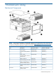
1 Illustrated parts catalog Mechanical Components NOTE: The list of part numbers is current and correct as of the publication of the document. Part numbers change often. Check the HP Partsurfer website (http://partsurfer.hp.com/search.aspx), to ensure you have the latest part numbers associated with this product.
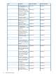
Item Description Spare part number Customer self repair — Bezel - Lower processor-memory drawer, frontal access AM426-69020 Mandatory1 7 Tool, T-15 Torx screwdriver 199630-001 Mandatory1 8 Blank, power supply 496058-001 Mandatory1 Not shown Plastics Kit AM426-69014 Mandatory1 Not shown Hardware kit - contains a 496058-001 heatsink blank, optical device blank, fan blank, full-length expansion slot cover, low-profile expansion slot cover, PCI retainer, PCI top retainer, PCI end retainer,
3 No: Non CSR—Alcuni componenti HP non sono progettati per la riparazione da parte del cliente. Per rispettare la garanzia, HP richiede che queste parti siano sostituite da un centro di assistenza autorizzato. Tali parti sono identificate da un “No” nel Catalogo illustrato dei componenti. — 1 Mandatory: Zwingend—Teile, die im Rahmen des Customer Self Repair Programms ersetzt werden müssen.
Illustrated parts catalog
System components NOTE: The list of part numbers is current and correct as of the publication of the document. Part numbers change often. Check the HP Partsurfer website (http://partsurfer.hp.com/search.aspx), to ensure you have the latest part numbers associated with this product.
Item Description Spare part number Customer self repair — 2 GB (128 MBx8), 133 PC3-10600R, DDR3 DIMM memory module 501533-001 Mandatory1 — 4 GB (256MBx4), 133 501534-001 MHz, PC3-10600R, DDR3 DIMM memory module1Rx4 Mandatory1 — 4 GB, PC3-10600R, DDR3-1333, single-rank memory module 595424-001 Mandatory1 — 4 GB PC3L 10600R 606426-001 DDR3-1333 memory module Mandatory1 — 8 GB PC3-10600R-DDR3-133 MHz RDIMM 501536-001 Mandatory1 — 8GB PC3L 10600R 606427-001 DDR3-1333 memory module Ma
Item Description Spare part number Customer self repair (24MB Level-2 cache, 6.40GT/s) — HP DL980 10 Core E7-2860 650015-001 2.26 processor kit Mandatory1 — HP DL980 10 Core E7-4870 653050-001 2.
Item Description Spare part number Customer self repair — a) 60 GB 3G SATA, 6.35 cm (2.5 in), MDL SSD 572071-B21 Mandatory1 — b) 120 GB, 3G SATA, 6.35 572073-B21 cm (2.5 in) MDL SSD Mandatory1 — c) 200 GB, SAS, 6.35 cm (2.5 in) SSD SLC drive 632492-B21 Mandatory1 — e) 400 GB, SAS, 6.35 cm (2.
Item Description Spare part number Customer self repair — HP NC382T PCIe Dual-Port Multifunction Gb Server Adapter 458492-B21 Mandatory1 — HP NC523SFP 10Gb 2P Adapter 593717-B21 Mandatory1 — HP NC524SFP Dual Port 10GbE Module 489892-B21 Mandatory1 — HP NC550SFP 2 -port PCIe 581201-B21 x8 Ethernet Adapter Mandatory1 — HP NC382T PCIe Dual Port 458491-001 Multifunction Gigabit Server Adapter Mandatory1 — SAS controller board, for use 462594-001 in the Smart Array P212 controller Mandato
Item Description — HP Smart Array cache 383280-B21 battery kit - For Smart Array P400 controller only Mandatory1 — HP Smart Array P800 controller Mandatory1 — HP P410/Zero Memory FIO 462860-B21 Smart Array controller Mandatory1 — HP Smart Array P410/256 controller 462862-B21 Mandatory1 — HP Smart Array P400/512 rmkt controller 462864-B21 Mandatory1 — HP Smart Array P410/256 MB BBWC controller 491195-B21 Mandatory1 — HP Smart Array P410 with 1GB FBWC controller 572532-B21 Mandat
Item Description Spare part number Customer self repair — PCIe one-port FC 81q HBA board 489190-001 Optional2 — HP StorageWorks CN1000E Dual Port Converged Network Adapter AW520A Mandatory1 — HP StorageWorks CN1000Q Dual Port Converged Network Adapter BS668A Mandatory1 — HP StorageWorks CN1100E Dual Port Converged Network Adapter BK835A Mandatory1 — HP SC11Xe HBA 412911-B21 Mandatory1 — HP StorageWorks PCIe U320e SCSI HBA AH627A Mandatory1 — HP IB 4X DDR CX-2 PCI-e G2 Dual Port
Item Description Spare part number Customer self repair Not shown HP 512 MB FBWC module 534915-B21 Mandatory1 Not shown HP 1 GB FBWC module 534562-B21 Mandatory1 Not shown FBWC module, 512 MB 578882-001 Mandatory1 Not shown FBWC capacitor pack 587324-001 Mandatory1 Not shown NC524SFP dual-port 10GBE 490712-001 module Optional2 Not shown Super capacitor module Optional2 — PCIe mezzanine NIC card - 436431-001 4-port, 1000base-T fiber connector (FC) Mandatory1 — 8-port externa
Item Description Spare part number — Dual-channel Ultra320 PCIE 445009-002 HBA Mandatory1 — PC board - HBA, 81Q, FC, PCIe 466515-001 Mandatory1 — SPS-BD,NC522SFP+ 10 gigabit,SE 468349-001 Mandatory1 — PCIe one-port FC 81q HBA board 489190-001 Mandatory1 — SPS-BD,NC112T,PCIe gigabit ADP 503827-001 Mandatory1 — SPS-BD NIC PXIE 4P 10/100/1000 539931-001 Mandatory1 — HP NC550SFP 10Gb 2-port 581201-B21 PCIe x8 Ethernet Adapter Mandatory1 — NC550SFP dual-port 10GbE 586444-001 server
Item Description Spare part number Customer self repair 138, 000 IOPS 75/25 R/W mix Not shown SPS-PCA Mini-DIMM 512MB 581135-001 Mandatory1 Not shown Battery, 3V, Lithium 153099-001 Mandatory1 Not shown Cable kit for DL980G7 AM426-69011 Mandatory1 Not shown a) Cable assembly, USB, video — Mandatory1 Not shown b) Cable assembly, power, UID — Mandatory1 Not shown c) Cable assembly, SAS power — Mandatory1 Not shown d) Cable, SATA DVD — Mandatory1 Not shown e) Cable assembly, SSD
1 Mandatory: Obligatoire—Pièces pour lesquelles la réparation par le client est obligatoire. Si vous demandez à HP de remplacer ces pièces, les coûts de déplacement et main d'oeuvre du service vous seront facturés. 2 Optional: Facultatif—Pièces pour lesquelles la réparation par le client est facultative. Ces pièces sont également conçues pour permettre au client d'effectuer lui-même la réparation.
2 Optional: Optioneel—Onderdelen waarvoor reparatie door de klant optioneel is. Ook deze onderdelen zijn ontworpen voor reparatie door de klant. Als u echter HP verzoekt deze onderdelen voor u te vervangen, kunnen daarvoor extra kosten in rekening worden gebracht, afhankelijk van het type garantieservice voor het product. 3 No: Nee—Sommige HP onderdelen zijn niet ontwikkeld voor reparatie door de klant.
2 Removal and replacement procedures Required tools You need the following items for some procedures: • Torx T-15 screwdriver (provided with the server) • Phillips screwdriver • Flathead screwdriver • Diagnostics Utility Safety considerations Before performing service procedures, review all the safety information. Preventing electrostatic discharge To prevent damaging the system, be aware of the precautions you need to follow when setting up the system or handling parts.
Power off the server WARNING! To reduce the risk of personal injury, electric shock, or damage to the equipment, disconnect the power cord to remove power from the server. The front panel Power On/Standby button does not completely shut off system power. Portions of the power supply and some internal circuitry remain active until the power cord is disconnected. NOTE: 1. 2. 3. 4. 5. 6. If installing a hot-plug device, it is not necessary to power down the server. Back up the server data.
To replace the component, reverse the removal procedure. DVD-ROM drive To remove the component: 1. Power down the server. 2. Extend the server from the rack. 3. Remove the access panel. 4. Disconnect the cable from the rear of the DVD-ROM drive. 5. Remove the DVD-ROM drive. To replace the component, reverse the removal procedure. Power supply blank Remove the component as indicated.
To replace the component, reverse the removal procedure. Hot-plug power supply The server supports up to eight hot-plug power supplies. Install all power supplies to provide full redundancy. HP recommends installing redundant hot-plug power supplies in pairs. To confirm the redundancy of your configuration, see the HP power advisor at the HP website (http://www.hp.com/go/hppoweradvisor).
To replace the component, reverse the removal procedure. Fans NOTE: If two fan fail or if a dual-rotor fan is removed and the "Shutdown" operating system pop-up alert appears, if the hot-plug fans are immediately replaced, the fan sensor state returns to "OK" (Green); however, the 60-second shutdown is not always aborted as it should be, and the system continues with its graceful shutdown. This issue occurs because HP Integrated Lights-Out 3 (iLO 3) Firmware Version 1.
To replace the component, reverse the removal procedure. Remove the upper or lower processor memory drawer or processor memory drawer blank 1. 2. 3. Power off the server (“Power off the server” (page 22)). Release the latches on the release lever. Lower the handle, and then extend the processor memory drawer from the server until the release latches catch. 4. Firmly holding the processor memory drawer, press the release buttons and then remove the drawer from the server.
Remove a processor memory drawer cover 1. 2. 3. Power off the server (“Power off the server” (page 22)). Remove the processor memory drawer. (“Remove the upper or lower processor memory drawer or processor memory drawer blank” (page 26)) Remove the processor memory drawer cover. The procedure is the same for the upper and lower processor memory drawers, and the processor memory drawer blank. CAUTION: XNC cabling (“XNC cabling” (page 102)) is required for eight processor systems.
5. Open the memory cartridge cover. 6. Remove the DIMMs from the failed memory cartridge: a. Open the DIMM slot latches. b. Remove the DIMM.
To replace the component: 1. Install the DIMMs in the replacement memory cartridge: a. Open the DIMM slot latches. b. Install the DIMM. 2. 3. Close the memory cartridge cover. Install the memory cartridge.
4. 5. 6. Install the processor memory drawer cover. Install the processor memory drawer. Power up the server. DIMMs To remove the component: 1. Power down the server. 2. Remove the processor memory drawer (“Remove the upper or lower processor memory drawer or processor memory drawer blank” (page 26)). 3. Remove the processor memory drawer cover (“Remove a processor memory drawer cover” (page 27)). 4. Remove the memory cartridge. 5. 30 Open the memory cartridge cover.
6. Remove the failed DIMM from the memory cartridge: a. Open the DIMM slot latches. b. Remove the DIMM. To replace the component: 1. Install the replacement DIMM in the memory cartridge: a. Open the DIMM slot latches. b. Install the DIMM.
2. 3. Close the memory cartridge cover. Install the memory cartridge. 4. 5. 6. Install the processor memory drawer cover. Install the processor memory drawer. Power up the server. Memory options This server contains eight memory cartridge connectors in each processor memory drawer. Each memory cartridge can contain eight DIMMs, for a total of 128 DIMMs, for a maximum memory configuration of 4 TB.
Depending on the processor model, the memory clock speed might be reduced to 1066 or 800 MHz. WARNING! There is not enough available PCI memory to allocate to all devices installed in the system. Devices which were not allocated requested resources may not operate properly.This occurs during the I/O configuration phase of POST, after the System ROM has allocated most of the available memory for some PCI devices, leaving insufficient memory for PCI devices that have not yet been configured.
NOTE: ProLiant DL980 G7 servers may be unable to provide MMIO (Memory Mapped I/O) memory to all slotted PCI devices during Power-On Self-Test (POST) in large I/O configurations, resulting in the following warning message: NOTE: When an HP ProLiant DL980 G7 server is configured with a DIMM that has an uninitialized SPD area, and the server is running any version of the System ROM detailed in the Scope section below, the Survey Utility in HP SmartStart will report the "Correctable Error Threshold Count" for t
DIMM identification To determine DIMM characteristics, use the label attached to the DIMM and the following illustration and table. Item Description Definition 1 Size — 2 Rank 1R = Single-rank2R = Dual-rank4R = Quad-rank 3 Data width x4 = 4-bitx8 = 8-bit 4 Memory speed 10600 = 1333-MHz8500 = 1066-MHz 5 DIMM type R = RDIMM (registered) For the latest supported memory information, see the QuickSpecs on the HP website (http:// www.hp.com).
• AMP modes Advanced ECC, Online Spare, and Mirrored Memory have further requirements beyond the ones listed here.
system. Each buffer has two DDR3 channels and can support up to four DIMMs for a total of eight DIMMs per cartridge. • Memory speed is not affected by number of DIMMs or ranks. All DIMMs run at the highest possible speed for a given processor. • DDR3 memory speed is a function of the QPI bus speed supported by the processor: • ◦ Processors with a QPI speed of 6.4 GT/s run memory at 1066 MT/s. ◦ Processors with a QPI speed of 5.6 GT/s run memory at 978 MT/s. ◦ Processors with a QPI speed of 4.
Memory performance optimization The server supports 128 DIMMS across eight Multi-core processors (64 DIMMs across four multi-core processors, in each processor memory drawer). While there are many DIMM population configurations that can support any total memory size, optimal performance is achieved when populated DIMMs can take advantage of the Intel® Xeon™ 7500-series processor architecture.
protection. For more information, see "Online Spare memory population guidelines (“Online Spare memory population guidelines” (page 39))." • Mirrored Memory mode provides the maximum protection against failed DIMMs. Uncorrectable errors in the DIMMs of one memory cartridge are corrected by the DIMMs in the mirrored cartridge. The two memory controllers of each processor form a mirrored pair using two memory cartridges.
When Online Spare memory is enabled, the first ranks of DIMM pair, 1A/8A, are set aside as the sparing ranks. Therefore, the available memory is reduced by the size of the first ranks of DIMM pair 1A/8A. If a DIMM rank on either of the SMI buses exceeds its correctable ECC threshold, then the contents of the failing DIMM ranks are copied to the spare DIMM ranks. Once the copy is complete, all memory accesses to the previous failing DIMM ranks go to the spare DIMM ranks.
To configure memory for Mirrored Memory mode, observe these additional constraints: • For the server to support Mirrored Memory, all processors must have a valid mirroring configuration. • The minimum allowable configuration is two memory cartridges per processor. • Both memory cartridges for each processor must be populated with the same DIMM configurations. • Both of the CPU sockets on the same QPI island must be loaded with identical memory. NOTE: When attempting to install or boot VMware ESX 4.
Heatsink To remove the component: 1. Power off the server (“Power off the server” (page 22)). 2. Remove the processor memory drawer (“Remove the upper or lower processor memory drawer or processor memory drawer blank” (page 26)). 3. Remove the processor memory drawer cover (“Remove a processor memory drawer cover” (page 27)). 4. Open the processor retaining bracket. 5. 42 Remove the heatsink.
To replace the component: 1. Clean the old thermal grease from the top of the processor with the alcohol swab. Allow the alcohol to evaporate before continuing. 2. Remove the heatsink protective cover. 3. 4. Install the heatsink. Close and lock the processor retaining bracket.
5. 6. 7. Install the processor memory drawer cover. Install the processor memory drawer. Power up the server. To replace the component, reverse the removal procedure. Processor WARNING! Use caution when installing the processor memory module or removing the processor memory module. The processor memory module is very heavy when fully populated. CAUTION: XNC cabling (“XNC cabling” (page 102)) is required for eight processor systems.
4. 5. Remove the heatsink (“Heatsink” (page 42)). Open the processor locking lever and the processor socket retaining bracket. 6. Using the processor tool, remove the processor from the system board: a. Line up the processor tool, ensuring the locking lever graphic on the tool is oriented correctly. b. Press in on the plastic tabs, and then place the tool on the processor. c. Release the tabs, and then carefully lift the processor and tool straight up. 7.
CAUTION: To avoid damage to the processor, do not touch the bottom of the processor, especially the contact area. To replace the component: 1. Carefully insert the processor into the processor installation tool. Handle the processor by the edges only, and do not touch the bottom of the processor, especially the contact area. 2. 46 Be sure the tool is oriented correctly. Align the processor installation tool with the socket, and then install the processor.
CAUTION: THE PINS ON THE SYSTEM BOARD ARE VERY FRAGILE AND EASILY DAMAGED. To avoid damage to the system board: 3. • Never install or remove a processor without using the processor installation tool. • Do not touch the processor socket contacts. • Do not tilt or slide the processor when lowering the processor into the socket. Press and hold the tabs on the processor installation tool to separate it from the processor, and then remove the tool.
4. Close the processor socket retaining bracket and the processor locking lever. CAUTION: Be sure to close the processor socket retaining bracket before closing the processor locking lever. The lever should close without resistance. Forcing the lever closed can damage the processor and socket, requiring system board replacement. 5. 6. 48 Clean the old thermal grease from the heatsink with the alcohol swab. Allow the alcohol to evaporate before continuing.
7. 8. Install the heatsink. Close and lock the processor retaining bracket. 9. Install the processor memory drawer cover. 10. Install the processor memory drawer. 11. Power up the server. Expansion slot cover CAUTION: To prevent improper cooling and thermal damage, do not operate the server unless all expansion slots have either an expansion slot cover or an expansion board installed. 1. 2. 3. Power down the server. Extend or remove the server from the rack. Remove the access panel.
4. Check for the shipping screw, and remove if present. 5. Open the latch, and remove the expansion slot cover. To replace the component, reverse the removal procedure. Low profile I/O expander 1. 2. 3. 50 Power off the server (“Power off the server” (page 22)). Press the release button, and open the lever. Slide the I/O expander out of the server. Place a hand under the component to support it as you remove it from the server.
4. Press the side buttons to remove the component cover. 5. To open the I/O card lock, push the blue tab, flip it back, then open the hinge forward.
6. Remove expansion slot covers as necessary. To replace the component, reverse the removal procedure. Non-hot-plug expansion board CAUTION: To prevent improper cooling and thermal damage, do not operate the server unless all expansion slots have either an expansion slot cover or an expansion board installed. To remove the component: 1. Power down the server. 2. Extend the server from the rack. 3. Remove the access panel. 4. Open the expansion slot latch. 5.
6. 7. Remove the retaining screw, if installed. Remove the expansion board. To replace the component, reverse the removal procedure.
4. 5. 6. 7. 8. If the existing cache is connected to a battery, observe the BBWC Status LED (“Battery pack LEDs” (page 99)). • If the LED is flashing every 2 seconds, data is still trapped in the cache. Restore system power, and then repeat the previous steps. • If the LED is not illuminated, disconnect the battery cable from the cache. Disconnect the cable. Remove the SPI board (“Remove the SPI board” (page 56)). Open the cache slot latches. Remove the cache module.
To replace the component, reverse the removal procedure. BBWC low profile I/O expander location BBWC procedures are the same for a BBWC located in the low profile I/O expander. Recovering data from the battery-backed write cache If the server fails, you can recover any data temporarily trapped in the BBWC by using the following procedure. CAUTION: Before starting this procedure, read the information about protecting against electrostatic discharge (“Preventing electrostatic discharge” (page 21)).
1. 2. Perform one of the following: • Set up a recovery server station using an identical server model. Do not install any internal drives or BBWC in this server. (This is the preferred option.) • Find a server that has enough empty drive bays to accommodate all the drives from the failed server and that meets all the other requirements for drive and array migration. Power down the failed server. If any data is trapped in the cache module, an amber LED on the module blinks every 15 seconds.
6. Remove all components from the failed SPI board. To replace the component, reverse the removal procedure. Systems Insight Display assembly CAUTION: When routing cables, always be sure that the cables are not in a position where they can be pinched or crimped. To remove the component: 1. Power off the server (“Power off the server” (page 22)). 2. Extend the server from the rack. 3. Remove the access panel. 4. Using a T-10 Torx screwdriver, release the two locking latches on the top of the SID bezel. 5.
To replace the component, reverse the removal procedure. Front bezel CAUTION: Removal of the bezel will most likely destroy the component. Have a replacement bezel on hand for immediate replacement before removing the bezel. 58 1. 2. 3. 4. 5. Power down the server. Extend the server from the rack. Remove the access panel. Remove the SID bezel (“Systems Insight Display assembly” (page 57)). Remove the seven screws from the right side of the chassis and eight screws from the left side of the chassis. 6.
7. Disengage the three bezel catches between the processor memory drawers, the three catches on the lower part of the bezel, and remove the bezel. To replace the component, reverse the removal procedure., inserting the left side tab as the bezel is placed into position. Solid state drive To remove the component: 1. Power down the server. 2. Extend the server from the rack. 3. Remove the access panel. 4. Disconnect the cable from the solid state drive. 5. Remove the solid state drive.
To replace the component, reverse the removal procedure. Battery If the server no longer automatically displays the correct date and time, you may need to replace the battery that provides power to the real-time clock. WARNING! The computer contains an internal lithium manganese dioxide, a vanadium pentoxide, or an alkaline battery pack. A risk of fire and burns exists if the battery pack is not properly handled. To reduce the risk of personal injury: • Do not attempt to recharge the battery.
To replace the component, reverse the removal procedure. For more information about battery replacement or proper disposal, contact an authorized reseller or an authorized service provider. I/O expansion board CAUTION: To prevent improper cooling and thermal damage, do not operate the server unless all expansion slots have either an expansion slot cover or an expansion board installed.
5. Lower the handle, and then extend the processor memory drawer from the server until the release latches catch. 6. Remove any expansion boards from the failed I/O expansion board (“Non-hot-plug expansion board” (page 52)). Remove the I/O expansion board: 7.
To replace the component, reverse the removal procedure. Expansion board options In the main I/O tray the server supports up to 11 expansion slots. The server ships with 5 PCI Express expansion slots.
To support the optional expansion slots, install one of the following options into the server: • PCI Express I/O Expansion Board—Adds six optional slots • PCI-X/PCI Express I/O Expansion Board—Adds five optional slots WARNING! There is not enough available PCI memory to allocate to all devices installed in the system. Devices which were not allocated requested resources may not operate properly.
NOTE: For ProLiant DL980 G7 servers, when there is an HP NC550SFP 10Gb 2-port PCIe x8 Ethernet Adapter in I/O slot 9 and an HP CN1000E Converged Network Adapter in I/O slot 10, during a network stress test (netperf), the connection in the second port of the CN1000E may be dropped. This issue may also occur when there is an HP CN1000E Converged Network Adapter in slot 9 and a HP CN1000E Converged Network Adapter in slot 10. This 1. 2. 3. 4.
◦ 1.28TB MCL PCIe ioDuo (part number 641027-B21) may experience thermal throttling when the server is running a System ROM dated July 27, 2010 (2010.07.27) or July 7, 2010 under both of the following conditions: ◦ An application has sustained high WRITE-bandwidth demands to the HP IO Accelerators. ◦ High ambient (data center) temperature (>25deg C).
NOTE: On an HP ProLiant DL980 G7 server with a 128 logical CPU configuration, if an HP NC382T PCI Express Dual Port Multifunction Gigabit Server Adapter is located in any Low Profile IO slot, the network connection may drop or the NIC may stop responding. This can occur while running Windows Server 2008 R2 and HP Network Configuration Utility for Windows Server 2008 R2 Version 10.10 or Version 10.20.
3. Lower the handle, and then remove the component from the server. CAUTION: Do not replace either the SPI board, main I/O board, upper CPU board, lower CPU board or XNC boards with new components at the same time. CAUTION: If replacing this component with a new part, all component firmware must be updated (“Flashing firmware using Smart Components” (page 77)) before replacing any other component. CAUTION: XNC cabling (“XNC cabling” (page 102)) is required for eight processor systems.
1. 2. 3. 4. 5. 6. 7. 8. 9. Power off the server (“Power off the server” (page 22)). Remove the server from the rack. Remove the access panel. Remove the processor memory drawer (“Remove the upper or lower processor memory drawer or processor memory drawer blank” (page 26)). Disconnect all cables from all installed expansion boards. Remove all expansion boards (“Non-hot-plug expansion board” (page 52)). Remove the SPI board (“Remove the SPI board” (page 56)). Remove the I/O expansion board, if installed.
4. 5. Slide the server back into the rack. Power up the server. After you replace the system board, you must re-enter the server serial number and the product ID. 1. During the server startup sequence, press the F9 key to access RBSU. 2. Select the Advanced Options menu. 3. Select Service Options. 4. Select Serial Number. The following warnings appear: WARNING! WARNING! WARNING! The serial number is loaded into the system during the manufacturing process and should NOT be modified.
6. 7. 8. 9. Remove the SPI board (“SPI board components” (page 96)). Remove the processor memory drawers (“Remove the upper or lower processor memory drawer or processor memory drawer blank” (page 26)). Remove the system board (“System board” (page 68)). Disconnect the upper cables from the power supply backplane: a. Disconnect the upper fan power cable. b. Remove the screws and disconnect the power cable. c. Remove the lower fan power cable from the cable management slot. 10.
11. Remove the two screws (if present), slide the plastic retainer to the rear of the server, and then remove the backplane. To replace the component, reverse the removal procedure. HP Trusted Platform Module The TPM is not a customer-removable part. CAUTION: Any attempt to remove an installed TPM from the system board breaks or disfigures the TPM security rivet.
If you suspect a TPM board failure, leave the TPM installed and remove the system board (“System board” (page 68)). Contact an HP authorized service provider for a replacement system board and TPM board.
3 Upgrading a 4s configuration to an 8s configuration To upgrade your DL980 G7 server from a 4s configuration to an 8s configuration: 1. Verify that the current system firmware is the latest available and if necessary upgrade the system firmware (“Flashing firmware” (page 75)). 2. Power off the server and disconnect the power cords (“Power off the server” (page 22)). 3. Remove the lower processor memory drawer (“Remove the upper or lower processor memory drawer or processor memory drawer blank” (page 26)).
4 Flashing firmware Flashing firmware requirements A firmware update is required when upgrading to Intel® Xeon® E7 Family processors or when replacing a SPI board, main I/O board, upper CPU board, lower CPU board, or XNC assembly with a new part. • The system firmware must be upgraded to a minimum level of HWM5.1. • If upgrading the CPUs.The CPUs and heatsinks must be replaced with the new CPUs and heatsinks. • The server must only contain supported I/O cards.
1-800-633-3600. For more information about Care Packs, see the HP website (http:// pro-aq-sama.houston.hp.com/services/cache/10950-0-0-225-121.html). • In other locations, see the Contact HP worldwide (in English) (http://welcome.hp.com/country/ us/en/contact_us.html) webpage. CAUTION: If replacing a SPI board, main I/O board, upper CPU board, lower CPU board, or XNC assembly with a new part, all component firmware must be updated before replacing any other component.
6. Disconnect all power cables from the server, and wait at least 30 seconds. CAUTION: After flashing the System Programmable Logic Devices, the power must cycle for the changes to take effect. All power cables must be unplugged for at least 30 seconds to allow the components to lose their residual charge. Pressing the power button is not sufficient. 7. 8. 9. 10. If installing new processors (“Processor” (page 44)), install them now. Connect the power cables to the server. Power up the server.
5. 6. 7. 8. Use the web interface to flash iLO. Power on the system. Boot the system to the OS. If running, disable SNMP agents service. • For a. b. c. d. • For Linux operating systems, enter Windows operating systems: Run Services. Select SNMP Service. Click Stop to stop the service. Click yes to stop the services indicated. service hp-snmp-agents stop . 9. Flash the FPGA using the FPGA Smart Component.
a. b. c. d. e. f. Download the Smart Component to a directory on the hard drive and change to that directory. • Download the FPGA firmware for the Windows operating system (ftp://ftp.hp.com/ pub/softlib2/software1/sc-windows-fw/p2013128495/v68025). • Download the FPGA firmware for the Linux operating system (ftp://ftp.hp.com/pub/ softlib2/software1/sc-linux-fw/p1486976799/v68026). From that drive and directory, execute the downloaded file. Linux users can execute "sh CPxxxxxx.scexe" where CPxxxxxx.
NOTE: When updating the individual components, the Smart Components will detect if the component is already at the correct revision by displaying the message pictured below. For components other than is CPLD, you can select "Close" and continue with the rest of the firmware update process. For the CPLD, you must select "install" and update the CPLD. TIP: a. b. c. d. e. f. The estimated time for this update is approximately one hour.
TIP: a. b. c. d. e. f. The estimated time for this update is approximately one hour. Download the Smart Component to a directory on the hard drive and change to that directory. • Download the FMP firmware for the Windows operating system (ftp://ftp.hp.com/ pub/softlib2/software1/sc-windows-fw/p2062200202/v68009). • Download the FMP firmware for the Linux operating system (ftp://ftp.hp.com/pub/ softlib2/software1/sc-linux-fw/p1438027470/v68004).
Procedure for Solaris and VMware operating systems For Solaris and VMware operating systems use the Flashing firmware using Offline Update Method.
5 Component identification Front panel components Item Description 1 Hard drive bay 1 2 Hard drive bay 2 3 Hard drive bay 3 4 Hard drive bay 4 5 Hard drive bay 5 6 Hard drive bay 6 7 Hard drive bay 7 8 Hard drive bay 8 9 Optical drive bay 10 UID button and LED 11 Health LED 12 NIC 1 LED 13 NIC 2 LED 14 NIC 3 LED 15 NIC 4 LED 16 Power on/Standby button and LED 17 SID 18 USB connectors 19 Video connector Front panel components 83
Item Description 20 Processor memory tray (upper) 21 Processor memory tray (lower) Front panel LEDs Item Description Status 1 UID button and LED Blue—Activated Blue (flashing)—Server being managed remotely Off—Deactivated 2 Health LED Green—Normal (system on) Amber (flashing)—Internal system health degraded Red (flashing)—Internal system health critical Off—Normal (system off) 3 NIC 1 LED Green—Linked to network Green (flashing)—Linked with activity on the network Off—No network connection
Item Description Status Green (flashing)—Linked with activity on the network Off—No network connection 7 Power on/Standby button and LED Amber—System has AC power and is in standby mode. Green—System has AC power and is powered on. Off—System has no AC power.
LED Component EXT HEALTH External component health Description Green—Normal (system on) Amber (flashing)—Internal system health degraded Red (flashing)—Internal system health critical Off—Normal (system off) POWER CAP Powering capping Green—System on or requesting power on Flashing amber—Power on denied Off—Standby OVER TEMP Over temperature Off—Normal Amber—Failed or missing component AMP Advanced memory protection Off—No protection Green—Protection enabled Amber—Memory failure occurred Amber
Processor and memory board configuration / logical (physical) location Upper processor memory board is shown on the left. Lower processor memory board is shown on the right.
Online/activity LED (green) Fault/UID LED (amber/blue) Interpretation Flashing regularly (1 Hz) Off Do not remove the drive. Removing a drive may terminate the current operation and cause data loss. The drive is rebuilding, or it is part of an array that is undergoing capacity expansion or stripe migration. Flashing irregularly Amber, flashing regularly (1 Hz) The drive is active, but a predictive failure alert has been received for this drive. Replace the drive as soon as possible.
Item Description 4 Serial connector 5 NIC connector 2 6 NIC connector 4 7 UID 8 NIC connector 3 9 NIC connector 1 10 Video connector 11 Keyboard connector 12 USB connectors 13 I/O expansion slots 14 Small form factor I/O expansion slots (optional) 15 XNC connectors 16 XNC management connector 17 Power supply 8 18 Power supply 7 19 Power supply 6 20 Power supply 5 21 Power supply 4 22 Power supply 3 23 Power supply 2 24 Power supply 1 Rear panel components 89
Item Description 4 Serial connector 5 NIC connector 2 6 NIC connector 4 7 UID 8 NIC connector 3 9 NIC connector 1 10 Video connector 11 Keyboard connector 12 USB connectors 13 I/O expansion slots 14 Small form factor I/O expansion slots (optional) 15 XNC connectors 16 XNC management connector 17 Power supply 8 18 Power supply 7 19 Power supply 6 20 Power supply 5 21 Power supply 4 22 Power supply 3 23 Power supply 2 24 Power supply 1 Rear panel components 89
Item Description 4 Serial connector 5 NIC connector 2 6 NIC connector 4 7 UID 8 NIC connector 3 9 NIC connector 1 10 Video connector 11 Keyboard connector 12 USB connectors 13 I/O expansion slots 14 Small form factor I/O expansion slots (optional) 15 XNC connectors 16 XNC management connector 17 Power supply 8 18 Power supply 7 19 Power supply 6 20 Power supply 5 21 Power supply 4 22 Power supply 3 23 Power supply 2 24 Power supply 1 Rear panel components 89
Item Description 4 Serial connector 5 NIC connector 2 6 NIC connector 4 7 UID 8 NIC connector 3 9 NIC connector 1 10 Video connector 11 Keyboard connector 12 USB connectors 13 I/O expansion slots 14 Small form factor I/O expansion slots (optional) 15 XNC connectors 16 XNC management connector 17 Power supply 8 18 Power supply 7 19 Power supply 6 20 Power supply 5 21 Power supply 4 22 Power supply 3 23 Power supply 2 24 Power supply 1 Rear panel components 89
Item Description 4 Serial connector 5 NIC connector 2 6 NIC connector 4 7 UID 8 NIC connector 3 9 NIC connector 1 10 Video connector 11 Keyboard connector 12 USB connectors 13 I/O expansion slots 14 Small form factor I/O expansion slots (optional) 15 XNC connectors 16 XNC management connector 17 Power supply 8 18 Power supply 7 19 Power supply 6 20 Power supply 5 21 Power supply 4 22 Power supply 3 23 Power supply 2 24 Power supply 1 Rear panel components 89
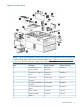
System board components Item Description 1 Optional I/O expansion board connectors: • PCI-X/PCI Express I/O expansion board • PCI Express I/O expansion board 94 2 Slot 7 PCIe2 x8 (4, 2, 1) 3 Slot 8 PCIe2 x8 (4, 2, 1) 4 Slot 9 PCIe2 x16 (8, 4, 2, 1) 5 Slot 10 PCIe2 x8 (4, 2, 1) 6 Slot 11 PCIe2 x8 (8, 4, 2, 1) 7 SPI board connector 8 Internal USB connectors (2) 9 NMI jumper 10 System maintenance switch 11 Optical drive connector 12 Video/USB connector 13 Solid state drive connecto
System maintenance switch The system maintenance switch (SW1) is an eight-position switch that is used for system configuration. The default position for all eight positions is Off. Position Description Function S1 iLO3 security Off = iLO3 security is enabled. On = iLO3 security is disabled. S2 Configuration lock Off = System configuration can be changed. On = System configuration is locked.
SPI board components Item Description 1 Mini SAS connectors (2) 2 SAS cache connector 3 TPM connector 4 Fan data connector 5 RMII connector 6 SD card slot 7 Battery 8 10Gb NIC connector 9 NIC cache connector 10 NIC 3 connector 11 NIC 1 connector 12 Video connector 13 Keyboard connector 14 USB connectors (2) 15 iLO 3 connector 16 Mouse connector 17 Serial connector 18 NIC 2 connector 19 NIC 4 connector Expansion board components • 96 PCI-X/PCI Express I/O expansion
Item Description 1 Slot 6 PCIe2 x16 (16, 8, 4, 2, 1) 2 Slot 4 PCIe2 x8 (4, 2, 1) 3 Slot 3 PCIe2 x16 (16, 8, 4, 2, 1) 4 Slot 2 PCI-X 5 Slot 1 PCI-X 1 • 1 Slot 4 is physically a x8 slot but operates electrically as a x4 slot.
Item Description 5 6 • Slot 1 PCIe1 x8 (4, 2, 1) 6 1 Slots 2, 3, 5 and 6 are physically x16 slots but operate electrically as x8 slots. 2 Slots 2, 3, 5 and 6 are physically x16 slots but operate electrically as x8 slots. 3 Slots 1 and 4 are physically x8 slots but operate electrically as x4 slots. 4 Slots 2, 3, 5 and 6 are physically x16 slots but operate electrically as x8 slots. 5 Slots 2, 3, 5 and 6 are physically x16 slots but operate electrically as x8 slots.
Device numbers Battery pack LEDs Item Color Description 1 Green System Power LED. This LED is on when the system is powered up and 12 V system power is available. This power supply is used to maintain the battery charge and provide supplementary power to the cache microcontroller. 2 Green Auxiliary Power LED. This LED is on when 3.3V auxiliary voltage is detected.
Item Color Description 3 Amber Battery Health LED. To interpret the illumination patterns of this LED, see the following table. 4 Green BBWC Status LED. To interpret the illumination patterns of this LED, see the following table. LED3 pattern LED4 pattern Interpretation Off Flashing (2 Hz) The system is powered down, and the cache contains data that has not yet been written to the drives. Restore system power as soon as possible to prevent data loss.
LED3 pattern LED4 pattern Interpretation battery pack is replaced. The life expectancy of a battery pack is typically more than 3 years.
6 Cabling XNC cabling CAUTION: XNC cabling (“XNC cabling” (page 102)) is required for eight processor systems. Failure to cable the XNC will result in the lower processor memory drawer not being recognized by the server. For best cable management, follow the recommend connection order.
1. 2. Make connections labeled 1 through 8 in the illustration. Refer to cabling illustrations and table to make connections 9 though 16. For example, to make the ninth connection, to upper board 1, use the cable connected to lower board 4.
7 Specifications Environmental Specifications Specification Value System inlet temperature — Operating 10° to 35°C (50° to 95°F) at sea level with an altitude derating of 1.0°C per every 305 m (1.8°F per every 1000 ft) above sea level to a maximum of 3050 m (10,000 ft), no direct sustained sunlight. Maximum rate of change is 10°C/hr (18°F/hr). The upper limit may be limited by the type and number of options installed. System performance may be reduced if operating with a fan fault or above 30°C (86°F).
Server Specifications Specification Value Dimension — Height 35.36 cm (13.92 in) Depth 87.63 cm (34.5 in) Width 48.26 cm (19.0 in) Weight (maximum) 93 kg (205 lb) Weight (one hard drive, power supply and processor installed) 75 kg (165 lb) Input requirement1 — Rated line voltage 100-240 VAC Rates input current 9.3A @ 100 VAC 9.5A @ 108-120 VAC 6.
sufficient power to operate normally. If the solution is deemed sufficient, a ROM-Based Setup Utility option, outlined below, can be used to allow the system to operate in this configuration. If the HP Power Advisor has determined that the server can be reliably powered at low-line power in this configuration, perform the following steps to override the Power Supply Requirements setting in ROM-Based Setup Utility (RBSU): 1. When the server halts, access RBSU. 2. Select "Advanced Options". 3.
8 Acronyms and abbreviations ABEND abnormal end AMP Advanced Memory Protection ASR Automatic Server Recovery BBWC battery-backed write cache FBWC flash-backed write cache GPU graphics processing unit IEC International Electrotechnical Commission iLO 3 Integrated Lights-Out 3 IML Integrated Management Log NVRAM nonvolatile memory ORCA Option ROM Configuration for Arrays PCIe peripheral component interconnect express PCI-X peripheral component interconnect extended POST Power-On Self Test RBSU R
SAS serial attached SCSI SD Secure Digital SFF small form factor SIM Systems Insight Manager SPI system peripheral interface SSD support software diskette TPM Trusted Platform Module UID unit identification USB universal serial bus 108 Acronyms and abbreviations
9 Documentation feedback HP is committed to providing documentation that meets your needs. To help us improve the documentation, send any errors, suggestions, or comments to Documentation Feedback. Include the document title and part number, version number, or the URL when submitting your feedback.
Index Symbols 4s to 8s upgrade, 74 B battery Battery, 60 SPI board components, 96 battery pack LEDs, 99 battery-backed write cache (BBWC) Battery pack LEDs, 99 Battery-backed write cache procedures, 53 BBWC low profile I/O expander location, 55 Recovering data from the battery-backed write cache, 55 Removing the BBWC battery pack, 54 SPI board components, 96 battery-backed write cache battery pack Battery-backed write cache procedures, 53 Removing the BBWC battery pack, 54 BBWC (battery-backed write cache)
K Removal and replacement procedures, 21 Required tools, 21 keyboard connector, 96 L S LED, health, 84 LED, iLO 3 link Rear panel components, 88 Rear panel LEDs, 90 LED, UID Front panel LEDs, 84 Rear panel LEDs, 90 LEDs, 91 LEDs, battery pack, 99 LEDs, front panel, 84 LEDs, hard drive Hard drive LED combinations, 87 Hard drive LEDs, 87 LEDs, power supply, 91 LEDs, rear panel, 90 LEDs, Systems Insight Display, 85 LEDs, unit identification (UID), 84 safety considerations, 21 safety information, 21 SAS b
V video connector, 96 VMware ESX Server, configuring, 82 X XNC Module, 67 112 Index