HP ProLiant MicroServer Gen8 Maintenance and Service Guide Abstract This document is for an experienced service technician. It is helpful if you are qualified in the servicing of computer equipment and trained in recognizing hazards in products with hazardous energy levels and are familiar with weight and stability precautions.
© Copyright 2013 Hewlett-Packard Development Company, L.P. The information contained herein is subject to change without notice. The only warranties for HP products and services are set forth in the express warranty statements accompanying such products and services. Nothing herein should be construed as constituting an additional warranty. HP shall not be liable for technical or editorial errors or omissions contained herein. Microsoft® and Windows® are U.S. registered trademarks of Microsoft Corporation.
Contents Customer self repair ...................................................................................................................... 5 Parts only warranty service ............................................................................................................................ 5 Illustrated parts catalog ............................................................................................................... 15 Mechanical components ..........................................
HP product QuickSpecs .............................................................................................................................. 63 HP Insight Diagnostics ................................................................................................................................ 63 HP Insight Diagnostics survey functionality .......................................................................................... 63 HP Insight Remote Support software ................................
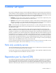
Customer self repair HP products are designed with many Customer Self Repair (CSR) parts to minimize repair time and allow for greater flexibility in performing defective parts replacement. If during the diagnosis period HP (or HP service providers or service partners) identifies that the repair can be accomplished by the use of a CSR part, HP will ship that part directly to you for replacement. There are two categories of CSR parts: • Mandatory—Parts for which customer self repair is mandatory.
Obligatoire - Pièces pour lesquelles la réparation par le client est obligatoire. Si vous demandez à HP de remplacer ces pièces, les coûts de déplacement et main d'œuvre du service vous seront facturés. Facultatif - Pièces pour lesquelles la réparation par le client est facultative. Ces pièces sont également conçues pour permettre au client d'effectuer lui-même la réparation.
In base alla disponibilità e alla località geografica, le parti CSR vengono spedite con consegna entro il giorno lavorativo seguente. La consegna nel giorno stesso o entro quattro ore è offerta con un supplemento di costo solo in alcune zone. In caso di necessità si può richiedere l'assistenza telefonica di un addetto del centro di supporto tecnico HP. Nel materiale fornito con una parte di ricambio CSR, HP specifica se il cliente deve restituire dei componenti.
defekte Teil nicht zurückschicken, kann HP Ihnen das Ersatzteil in Rechnung stellen. Im Falle von Customer Self Repair kommt HP für alle Kosten für die Lieferung und Rücksendung auf und bestimmt den Kurier-/Frachtdienst. Weitere Informationen über das HP Customer Self Repair Programm erhalten Sie von Ihrem Servicepartner vor Ort. Informationen über das CSR-Programm in Nordamerika finden Sie auf der HP Website unter (http://www.hp.com/go/selfrepair).
enviara el componente defectuoso requerido, HP podrá cobrarle por el de sustitución. En el caso de todas sustituciones que lleve a cabo el cliente, HP se hará cargo de todos los gastos de envío y devolución de componentes y escogerá la empresa de transporte que se utilice para dicho servicio. Para obtener más información acerca del programa de Reparaciones del propio cliente de HP, póngase en contacto con su proveedor de servicios local.
Neem contact op met een Service Partner voor meer informatie over het Customer Self Repair programma van HP. Informatie over Service Partners vindt u op de HP website (http://www.hp.com/go/selfrepair). Garantieservice "Parts Only" Het is mogelijk dat de HP garantie alleen de garantieservice "Parts Only" omvat. Volgens de bepalingen van de Parts Only garantieservice zal HP kosteloos vervangende onderdelen ter beschikking stellen.
No caso desse serviço, a substituição de peças CSR é obrigatória. Se desejar que a HP substitua essas peças, serão cobradas as despesas de transporte e mão-de-obra do serviço.
Customer self repair 12
Customer self repair 13
Customer self repair 14
Illustrated parts catalog Mechanical components Item Description Spare part number Customer self repair (on page 5) 1 Chassis cover 724494-001 Mandatory1 2 Optical drive blank 724499-001 Mandatory1 3 LFF non-hot-plug drive carrier* 691585-001 Mandatory1 4 Front bezel assembly 724490-001 Mandatory1 5 System board tray 724500-001 Mandatory1 6 Heatsink 724501-001 Optional2 * When no drive is installed in the non-hot-plug drive carrier, it serves as a blank for a non-hot-plug drive
Optional—Parts for which customer self repair is optional. These parts are also designed for customer self repair. If, however, you require that HP replace them for you, there may or may not be additional charges, depending on the type of warranty service designated for your product. 3 No—Some HP parts are not designed for customer self repair. In order to satisfy the customer warranty, HP requires that an authorized service provider replace the part.
Optional: Opcional—Peças cujo reparo feito pelo cliente é opcional. Essas peças também são projetadas para o reparo feito pelo cliente. No entanto, se desejar que a HP as substitua, pode haver ou não a cobrança de taxa adicional, dependendo do tipo de serviço de garantia destinado ao produto. 3 No: Nenhuma—Algumas peças da HP não são projetadas para o reparo feito pelo cliente. A fim de cumprir a garantia do cliente, a HP exige que um técnico autorizado substitua a peça.
System components Item Description Spare part number Customer self repair (on page 5) 7 LFF non-hot-plug drive bracket assembly 724493-001 Mandatory1 8 Capacitor pack 671353-001 Mandatory1 9 Front I/O module assembly 724492-001 No3 10 SATA DVD-RW optical drive (9.5 mm, 0.37 in) 724498-001 Mandatory1 11 LFF non-hot-plug 6G SATA drives (8.89 cm, 3.
Item Description Spare part number Customer self repair (on page 5) c) 4 GB, dual-rank x8 PC3-12800E-11* 684034-001 Mandatory1 d) 4 GB, dual-rank x8 PC3L-10600E-9* 664695-001 Mandatory1 e) 8 GB, dual-rank x8 PC3-12800E-11* 684035-001 Mandatory1 f) 8 GB, dual-rank x8 PC3L-10600E-9* 664696-001 Mandatory1 17 System fan 724491-001 Mandatory1 18 Ambient temperature sensor cable* 725205-001 No3 * Not shown Mandatory—Parts for which customer self repair is mandatory.
No: No—Algunos componentes no están diseñados para que puedan ser reparados por el usuario. Para que el usuario haga valer su garantía, HP pone como condición que un proveedor de servicios autorizado realice la sustitución de estos componentes. Dichos componentes se identifican con la palabra “No” en el catálogo ilustrado de componentes. 3 Mandatory: Verplicht—Onderdelen waarvoor Customer Self Repair verplicht is.
Removal and replacement procedures Required tools You need the following items for some procedures: • T-10/T-15 Torx screwdriver (on page 74) • HP Insight Diagnostics (on page 63) Safety considerations Before performing service procedures, review all the safety information. Preventing electrostatic discharge To prevent damaging the system, be aware of the precautions you need to follow when setting up the system or handling parts.
This symbol on an RJ-45 receptacle indicates a network interface connection. WARNING: To reduce the risk of electric shock, fire, or damage to the equipment, do not plug telephone or telecommunications connectors into this receptacle. This symbol indicates the presence of a hot surface or hot component. If this surface is contacted, the potential for injury exists. WARNING: To reduce the risk of injury from a hot component, allow the surface to cool before touching.
• Remove the front bezel (on page 25). • Remove the chassis cover (on page 26). • Remove the system board assembly (on page 28). Power down the server Before powering down the server for any upgrade or maintenance procedures, perform a backup of critical server data and programs. WARNING: To reduce the risk of personal injury, electric shock, or damage to the equipment, remove the power cord to remove power from the server.
Open the front bezel If the front bezel is not secured from inside the chassis, open the bezel. If the front bezel is secured from inside the chassis, do the following (Perform steps 1 to 3 only if the server is turned on.): 1. Power down the server (on page 23). 2. Disconnect the power cord from the AC source. 3. Disconnect the power cord from the server. 4. Remove the chassis cover (on page 26). 5. Slide the release tab upward to unlock the front bezel from the chassis.
6. Open the front bezel. Remove the front bezel If the front bezel is not secured from inside the chassis, open the front bezel, and then release the hinges from the front panel. If the front bezel is secured from inside the chassis, do the following (Perform steps 1 to 3 only if the server is turned on.): 1. Power down the server (on page 23). 2. Disconnect the power cord from the AC source. 3. Disconnect the power cord from the server. 4. Remove the chassis cover (on page 26).
5. Slide the release tab upward to unlock the front bezel from the chassis. 6. Open the front bezel. 7. Release the bezel hinges from the front panel. Remove the chassis cover 1. Power down the server (on page 23). 2. Disconnect the power cord from the AC source. 3. Disconnect the power cord from the server. 4. Disconnect all peripheral cables from the server. 5. If a Kensington security cable is installed, disconnect it from the rear panel.
7. Slide the chassis cover toward the rear panel, and then lift it to remove it from the chassis. Install the chassis cover 1. Align the installation markers on the chassis cover with those located on the front edge of the chassis, and then slide the chassis cover back onto the server. 2. Tighten the rear thumbscrews to secure the chassis cover in place. 3. Connect the peripheral devices to the server. 4. If a Kensington security cable was removed, connect it to the rear panel.
7. Power up the server. Remove the system board assembly 1. Power down the server (on page 23). 2. Disconnect the power cord from the AC source. 3. Disconnect the power cord from the server. 4. Remove the chassis cover (on page 26). 5. It is recommended that you take a picture of the current system board cable connections for reference during server reassembly. 6. If the drive cage is connected to a storage controller board, disconnect the Mini-SAS cable from the board. 7.
8. Press the system board tray latch. 9. Slide the system board assembly completely out of the chassis.
Install the system board assembly 1. Slide the system board assembly into the chassis. 2. Connect all cables disconnected from the system board and/or expansion board. Drive carrier CAUTION: To prevent improper cooling and thermal damage, do not operate the server unless all bays are populated with either a component or a blank. To remove the component: 1. Open the front bezel (on page 24). 2. Remove the drive carrier. To replace the component, slide the component into the bay until it clicks.
LFF non-hot-plug drive CAUTION: To prevent improper cooling and thermal damage, do not operate the server unless all bays are populated with either a component or a blank. To remove the component: 1. Back up all server data on the drive. 2. Power down the server (on page 23). 3. If the front bezel is not secured from inside the chassis, open the bezel. 4. If the front bezel is secured from inside the chassis, do the following: a. Disconnect the power cord from the AC source. b.
e. Release the bezel hinges from the front panel. 5. Remove the drive. 6. Remove the drive from the carrier. To replace the component, reverse the removal procedure.
Optical drive blank To remove the component: 1. Power down the server (on page 23). 2. Disconnect the power cord from the AC source. 3. Disconnect the power cord from the server. 4. Remove the chassis cover (on page 26). 5. Press the optical drive blank release latches, and then pull the blank out of the drive bay. To replace the component, reverse the removal procedure.
6. Press the optical drive release lever, and then push the drive out of the bay. To replace the component, reverse the removal procedure.
4. Remove the chassis cover (on page 26). CAUTION: When connecting or disconnecting the capacitor pack cable, the connectors on the cache module and cable are susceptible to damage. Avoid excessive force and use caution to avoid damage to these connectors. 5. Disconnect the capacitor pack cable from the cache module. 6. Remove the cache module. To replace the component, reverse the removal procedure.
2. Disconnect the power cord from the AC source. 3. Disconnect the power cord from the server. 4. Remove the chassis cover (on page 26). 5. If the existing cache module is connected to a capacitor pack, observe the FBWC module LEDs: o If a backup is in progress, wait for the backup to complete. o If the backup is complete, or if the cache has failed, remove the controller from the server, and then continue with the next step. 6. Disconnect the capacitor pack cable from the cache module. 7.
Recovering data from the flash-backed write cache If the server fails, use the following procedure to recover data temporarily stored in the FBWC. CAUTION: Before starting this procedure, read the information about protecting against electrostatic discharge ("Preventing electrostatic discharge" on page 21). 1. Perform one of the following: o Set up a recovery server using an identical server model. Do not install any internal drives or FBWC in this server. (HP recommends this option.
c. 9. To detach the cover from the chassis, push the latches toward the front. Remove the power button/LED module: a. Release the module cable from the top chassis clips. b. Remove the module bracket screw. c. Remove the module bracket.
d. Press the two module latches together, and then pull the module from the chassis. 10. Remove the front USB module: a. Remove the USB module screw. b. Pull the USB module out of the chassis. 11. Remove the front I/O module assembly: a. Pull the blue loop to disconnect the front I/O module cable from the system board. b. Release the cable from the two chassis cable clips located on the underside of the drive cage.
c. Release the cable from the left-side cable clip. d. Pull the module cable out through the top chassis opening. e. Pull the entire assembly out of the front USB module chassis opening. To replace the component, reverse the removal procedure. Ambient temperature sensor cable To remove the component: 1. Power down the server (on page 23). 2. Disconnect the power cord from the AC source. 3. Disconnect the power cord from the server. 4. Remove the front bezel (on page 25). 5.
6. Remove the ambient temperature sensor cable: a. Open the left-side chassis cable clip. b. If more working room is required, disconnect the following cables from the system board: — System board power cable — Optical drive SATA cable — Mini-SAS cable c. Pull the brown loop to disconnect the sensor cable from the system board. d. Detach the cable end with the rubber stopper from the chassis. e. Remove the rubber stopper from the sensor cable. To replace the component, reverse the removal procedure.
3. Disconnect the power cord from the server. 4. Open the front bezel (on page 24). 5. Remove all drives ("LFF non-hot-plug drive" on page 31) and drive carriers ("Drive carrier" on page 30). 6. If the chassis cover was not removed in step 4, remove it ("Remove the chassis cover" on page 26). 7. Open the left and right side chassis cable clips to allow the drive cable removal. 8. o Right side cable clip o Left side cable clip Disconnect the drive power cable: a.
c. Disconnect the drive power cable from the PSU 4-pin drive power connector. d. Pull the drive power cable out from the right side chassis opening. 9.
a. Disconnect the Mini-SAS cable from the system board or from a storage controller. b. Pull the Mini-SAS cable out from the left side chassis opening toward the right side one until the cable is released from the chassis. 10. Remove the non-hot-plug drive cage bracket: a. Remove the bracket screws. b. To release the bracket from the chassis tabs, pull it up and move it backward.
c. Pull the bracket out of the chassis. To replace the component, reverse the removal procedure. System fan To remove the component: 1. Power down the server (on page 23). 2. Disconnect the power cord from the AC source. 3. Disconnect the power cord from the server. 4. Remove the chassis cover (on page 26). 5. Disconnect the fan cable. 6. Remove the screws securing the system fan, and then remove the fan. To replace the component, reverse the removal procedure.
Integrated power supply WARNING: To reduce the risk of personal injury from hot surfaces, allow the power supply or power supply blank to cool before touching it. To remove the component: 1. Power down the server (on page 23). 2. Disconnect the power cord from the AC source. 3. Disconnect the power cord from the server. 4. Remove the chassis cover (on page 26). 5. If installed, remove the optical drive ("Optical drive" on page 33). 6. Disconnect all power supply cables: a.
c. Remove the power supply. To replace the component, reverse the removal procedure. Expansion board To remove the component: 1. Power down the server (on page 23). 2. Disconnect the power cord from the AC source. 3. Disconnect the power cord from the server. 4. Remove the chassis cover (on page 26). 5. Disconnect all cables connected to the expansion board. 6. To open the expansion slot cover retainer latch, press it. 7. If the expansion board is secured with a screw, remove the screw.
8. Remove the expansion board. To replace the component, reverse the removal procedure. DIMMs General DIMM slot population guidelines • The server supports a maximum of 16 GB memory using two 8 GB single-rank or dual-rank UDIMMs. • The server supports up to 1600 MT/s ECC UDIMMs. • LV DIMMs operate at 1.35 V instead of the 1.5 V for standard DDR3 DIMMs. LV DIMMs can be installed in this server, but the system does not recognize the reduced power consumption feature.
Removing a DIMM 1. Power down the server (on page 23). 2. Disconnect the power cord from the AC source. 3. Disconnect the power cord from the server. 4. Remove the chassis cover (on page 26). 5. Open the DIMM slot latches. 6. Remove the DIMM. To replace the component, reverse the removal procedure. Heatsink To remove the component: 1. Power down the server (on page 23). 2. Disconnect the power cord from the AC source. 3. Disconnect the power cord from the server. 4.
b. Completely loosen all screws in the same sequence. c. Remove the heatsink from the processor backplate. To replace the component: 1. Clean the old thermal grease from the processor with the alcohol swab. Allow the alcohol to evaporate before continuing. 2. Remove the thermal interface protective cover from the heatsink. CAUTION: Heatsink retaining screws should be tightened or loosened in diagonally opposite pairs (in an "X" pattern).
c. Finish the installation by completely tightening the screws in the same sequence. 4. Install the system board assembly (on page 30). 5. Install the chassis cover (on page 27). 6. Connect the power cord to the server. 7. Connect the power cord to the AC power source. 8. Press the Power On/Standby button. The server exits standby mode and applies full power to the system. The system power LED changes from amber to green.
CAUTION: The pins on the processor socket are very fragile. Any damage to them may require replacing the system board. 7. Open the processor locking lever, and then open the processor retaining bracket. 8. Grasp the processor by the edges, and then lift it out of the socket. To replace the component: CAUTION: Failure to completely open the processor locking lever prevents the processor from seating during installation, leading to hardware damage.
2. Close the processor retaining bracket, and then secure the processor locking lever. 3. Clean the old thermal grease from the heatsink with the alcohol swab. Allow the alcohol to evaporate before continuing. 4. Apply all the grease to the top of the processor in the following pattern to ensure even distribution. 5. Install the heatsink ("Heatsink" on page 49). 6. Install the system board assembly (on page 30). 7. Install the chassis cover (on page 27). 8.
To remove the system board: 1. Power down the server (on page 23). 2. Disconnect the power cord from the AC source. 3. Disconnect the power cord from the server. 4. Remove the chassis cover (on page 26). 5. Remove the system board assembly. WARNING: To reduce the risk of personal injury from hot surfaces, allow the heatsink to cool before touching it. CAUTION: Heatsink retaining screws should be tightened or loosened in diagonally opposite pairs (in an "X" pattern).
8. Grasp the processor by the edges, and then lift it out of the socket. 9. Remove all DIMMs ("Removing a DIMM" on page 49). 10. If installed, remove the expansion board ("Expansion board" on page 47). 11. Remove the failed system board.
To replace the system board: 1. Install the system board. CAUTION: Failure to completely open the processor locking lever prevents the processor from seating during installation, leading to hardware damage. CAUTION: To avoid damage to the processor, do not touch the bottom of the processor, especially the contact area. 2. Open the processor locking lever, and then open the processor retaining bracket.
3. Remove the processor socket cover. CAUTION: THE PINS ON THE SYSTEM BOARD ARE VERY FRAGILE AND EASILY DAMAGED. To avoid damage to the system board: • Do not touch the processor socket contacts. • Do not tilt or slide the processor when lowering the processor into the socket. 4. Install the processor. Use the notches on both sides of the processor to properly align it into the socket. CAUTION: Be sure to close the processor socket retaining bracket before closing the processor locking lever.
5. Close the processor retaining bracket, and then secure the processor locking lever. 6. Clean the old thermal grease from the heatsink and the top of the processor with the alcohol swab. Allow the alcohol to evaporate before continuing. 7. Apply all the grease to the top of the processor in the following pattern to ensure even distribution. CAUTION: Heatsink retaining screws should be tightened or loosened in diagonally opposite pairs (in an "X" pattern).
c. Finish the installation by completely tightening the screws in the same sequence. CAUTION: When returning a damaged system board to HP, always install all processor socket covers to prevent damage to the processor sockets and system board. 9. Install the processor socket cover on the failed system board. 10. Install the system board assembly (on page 30). 11. Install the DIMMs. 12. If removed, install the expansion board. 13. Install the chassis cover (on page 27). 14.
2. Select the Advanced Options menu. 3. Select Service Options. 4. Select Serial Number. The following warning appears: Warning: The serial number should ONLY be modified by qualified service personnel. This value should always match the serial number located on the chassis. 5. Press the Enter key to clear the warning. 6. Enter the serial number and press the Enter key. 7. Select Product ID.
7. Remove the battery. IMPORTANT: Replacing the system board battery resets the system ROM to its default configuration. After replacing the battery, reconfigure the system through RBSU. To replace the component, reverse the removal procedure. For more information about battery replacement or proper disposal, contact an authorized reseller or an authorized service provider. HP Trusted Platform Module The TPM is not a customer-removable part.
Troubleshooting Troubleshooting resources The HP ProLiant Gen8 Troubleshooting Guide, Volume I: Troubleshooting provides procedures for resolving common problems and comprehensive courses of action for fault isolation and identification, issue resolution, and software maintenance on ProLiant servers and server blades. To view the guide, select a language: • English (http://www.hp.com/support/ProLiant_TSG_v1_en) • French (http://www.hp.com/support/ProLiant_TSG_v1_fr) • Spanish (http://www.hp.
Diagnostic tools HP product QuickSpecs For more information about product features, specifications, options, configurations, and compatibility, see the product QuickSpecs on the HP Product Bulletin website (http://www.hp.com/go/productbulletin).
The HP Insight Remote Support software extends the HP enterprise remote support portfolio for customers with small and medium size IT environments. The software is available in two variants: • HP Insight Remote Support 7.x software is optimized to support up to 500 managed systems and can be installed on a Windows ProLiant hosting device or a Windows ESXi Virtual Machine. It can be integrated easily to work with a supported version of HP Systems Insight Manager. HP Insight Remote Support 7.
• From within HP Insight Diagnostics (on page 63) USB support and functionality USB support HP provides standard USB 2.0 support, standard USB 3.0 support, and legacy USB support. Standard support is provided by the OS through the appropriate USB device drivers. Before the OS loads, HP provides support for USB 2.0 devices through legacy USB support, which is enabled by default in the system ROM. USB 3.0 ports are not functional before the OS loads. The native OS provides USB 3.
Component identification Front panel components Item Description 1 USB 2.
Front panel LEDs and buttons Item Description Status 1 Power On/Standby button and system power LED Solid green = System on Flashing green (1 Hz/cycle per sec) = Performing power on sequence Solid amber = System in standby Off = No power present* 2 NIC status LED Solid green = Link to network Flashing green (1 Hz/cycle per sec) = Network active Off = No network activity 3 Drive status LED Solid green = System on Flashing green = Drive activity Off = System in standby or no power present 4 Heal
Rear panel components Item Description 1 Kensington security slot 2 Power supply 3 Serial number/iLO information tag* 4 Power cord connector 5 Dedicated iLO connector 6 Video connector 7 USB 3.0 connectors 8 USB 2.0 connectors 9 NIC connector 2 10 NIC connector 1/shared iLO connector 11 System fan * The serial number/iLO information tag shows the server serial number and the default iLO account information.
Rear panel LEDs and buttons Item Description Status 1 NIC link LED Solid green = Link exists Off = No link exists 2 NIC status LED Solid green = Link to network Flashing green (1 Hz/cycle per sec) = Network active Off = No network activity System board components Component identification 69
Item Description 1 Fan connector 2 DIMM slots 3 Front I/O connector 4 Processor socket 5 TPM connector 6 System battery 7 Mini-SAS connector 8 Optical drive SATA connector 9 Ambient temperature sensor connector 10 24-pin system board power connector 11 Internal USB 2.
DIMM slot locations DIMM slots are numbered sequentially (1 through 4) for the processor. The supported AMP modes use the letter assignments for population guidelines. System maintenance switch Position Default Function S1 Off Off = iLO security is enabled. On = iLO security is disabled. S2 Off Off = System configuration can be changed. On = System configuration is locked. S3 Off Reserved S4 Off Reserved S5 Off Off = Power-on password is enabled. On = Power-on password is disabled.
CAUTION: Clearing CMOS and/or NVRAM deletes configuration information. Be sure to properly configure the server or data loss could occur. NMI functionality An NMI crash dump creates a crash dump log before resetting a system which is not responding. Crash dump log analysis is an essential part of diagnosing reliability problems, such as failures of operating systems, device drivers, and applications. Many crashes freeze a system, and the only available action for administrators is to restart the system.
FBWC module LED definitions The FBWC module has three single-color LEDs (one amber and two green). The LEDs are duplicated on the reverse side of the cache module to facilitate status viewing. 1 - Amber 2 - Green 3 - Green Interpretation Off Off Off The cache module is not powered. Off Flashing 0.5 Hz Flashing 0.5 Hz The cache microcontroller is executing from within its boot loader and receiving new flash code from the host controller.
Fan location The server has one system fan located at the rear of the server. T-10/T-15 Torx screwdriver The server includes a T-10/T-15 Torx screwdriver located on the front panel. Use this screwdriver to loosen screws during hardware configuration procedures.
Cabling Cabling overview This section provides guidelines that help you make informed decisions about cabling the server and hardware options to optimize performance. For information on cabling peripheral components, refer to the white paper on high-density deployment at the HP website (http://www.hp.com/products/servers/platforms). CAUTION: When routing cables, always be sure that the cables are not in a position where they can be pinched or crimped.
• Mini-SAS cable connected to controller board Item Description 1 4-pin power cable (connected to the PSU P2 cable) 2 Mini-SAS cable Capacitor pack cabling Cabling 76
Optical drive cabling Item Description 1 4-pin power connector (connected to the PSU P3 cable) of the optical drive SATA Y-cable 2 Common end of the optical drive SATA Y-cable 3 SATA connector of the optical drive SATA Y-cable Front I/O assembly cabling Cabling 77
Ambient temperature sensor cabling System fan cabling Cabling 78
Power supply cabling Item PSU cable marker Description 1 P3 4-pin optical drive power cable 2 P2 4-pin drive power cable 3 P1 24-pin system board power cable Cabling 79
Specifications Environmental specifications Specification Value Temperature range* Operating 10°C to 35°C (50°F to 95°F) Nonoperating -30°C to 60°C (-22°F to 140°F) Relative humidity (noncondensing) Operating, maximum wet bulb 10% to 90% temperature of 28°C (82.4°F) Nonoperating, maximum wet 5% to 95% bulb temperature of 38.7°C (101.7°F) * All temperature ratings shown are for sea level. An altitude derating of 1°C per 304.8 m (1.8°F per 1,000 ft) to 3048 m (10,000 ft) is applicable.
Rated input voltage 100 V AC to 240 V AC Rated input frequency 47 Hz to 63 Hz Rated input current 3.
Acronyms and abbreviations ABEND abnormal end AMP Advanced Memory Protection ASR Automatic Server Recovery CSR Customer Self Repair DDR3 double data rate-3 FBWC flash-backed write cache HP SIM HP Systems Insight Manager iLO Integrated Lights-Out IML Integrated Management Log LFF large form factor LV DIMM low-voltage DIMM NMI nonmaskable interrupt Acronyms and abbreviations 82
NVRAM nonvolatile memory PCIe Peripheral Component Interconnect Express POST Power-On Self Test PSU power supply unit RBSU ROM-Based Setup Utility RDIMM registered dual in-line memory module SAS serial attached SCSI SATA serial ATA SD Secure Digital SPP HP Service Pack for ProLiant TPM Trusted Platform Module UDIMM unregistered dual in-line memory module USB universal serial bus Acronyms and abbreviations 83
Documentation feedback HP is committed to providing documentation that meets your needs. To help us improve the documentation, send any errors, suggestions, or comments to Documentation Feedback (mailto:docsfeedback@hp.com). Include the document title and part number, version number, or the URL when submitting your feedback.
Index A ambient temperature sensor cable 40 ambient temperature sensor, cabling 78 Automatic Server Recovery (ASR) 65 B bezel, opening 24 bezel, removing 25 C cabling, drive cage 75 cabling, FBWC 76 cabling, front I/O 77 cabling, internal power 79 cabling, optical drive 77 cache module 34, 73 capacitor pack 35 capacitor pack cabling 76 chassis cover, installing 27 chassis cover, removing 26 clearing NVRAM 71 CMOS 71 components, front panel 66 components, mechanical 15 components, rear panel 68 components,
K Q Kensington security slot 68 QuickSpecs 63 L R LED, system power 67 LEDs, drive 67 LEDs, FBWC module 73 LEDs, front panel 67 LEDs, NIC 67, 69 LEDs, rear panel 69 low-voltage DIMMs 48 rear panel buttons 69 rear panel components 68 rear panel LEDs 69 recovering the data from the cache 37 re-entering the server serial number 53 removal and replacement procedures 21 replacement procedures 21 required tools 21 requirements, environmental 80 ROM legacy USB support 65 ROM-Based Setup Utility (RBSU) 64 M
U USB connectors 69 USB support 65 utilities 63 V video connector 69 W warnings 22 weight 80 Index 87