HP ProLiant ML110 Generation 2 Server Maintenance and Service Guide February 2005 (First Edition) Part Number 375599-001
© Copyright 2005 Hewlett-Packard Development Company, L.P. The information contained herein is subject to change without notice. The only warranties for HP products and services are set forth in the express warranty statements accompanying such products and services. Nothing herein should be construed as constituting an additional warranty. HP shall not be liable for technical or editorial errors or omissions contained herein. Microsoft and Windows are U.S. registered trademarks of Microsoft Corporation.
Contents Chapter 1 Illustrated Parts Catalog Customer Self Repair (CSR) ..................................................................................................................... 1-1 Mechanical Parts Exploded View ............................................................................................................. 1-2 System Components Exploded View ........................................................................................................ 1-3 HP Contact Information ........
Contents Chapter 3 Diagnostic Tools PhoenixBIOS Software ..............................................................................................................................3-1 PhoenixBIOS Setup Utility .................................................................................................................3-2 Power-On Self Test (POST)..............................................................................................................3-14 Diagnostics for Windows..................
1 Illustrated Parts Catalog This chapter provides the illustrated parts breakdown and spare parts lists for the HP ProLiant ML110 Generation 2 server. Information for contacting HP is also provided. Customer Self Repair (CSR) What is customer self repair? HP's customer self-repair program offers you the fastest service under either warranty or contract. It enables HP to ship replacement parts directly to you so that you can replace them. Using this program, you can replace parts at your own convenience.
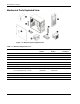
Illustrated Parts Catalog Mechanical Parts Exploded View Figure 1-1: Mechanical parts exploded view Table 1-1: Mechanical Spare Parts List Item Description Assembly Number Spare Part Number Customer Self Repair 1 Front bezel 377587-001 382953-001 Yes 2 Access panel — — — 3 Air baffle 385712-001 385758-001 Yes 4 PCI retainer clips — — Yes 5 Release lever (for the full-height drive bay) — — Yes 6 Feet (4) — — Yes 382992-001 Hard disk drive (HDD) cage 7 Non-hot-plug HDD c
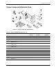
Illustrated Parts Catalog System Components Exploded View Figure 1-2: System components exploded view Table 1-2: System Components Spare Parts List Item Description Assembly Number Spare Part Number Customer Self Repair 1 System fan 381458-001 382109-001 Yes 2 Processor heatsink-cooling fan (HSF) assembly 379265-001 382110-001 No 3 Processor a) Intel Celeron D 2.8 GHz/533 MHz FSB with 256 KB L2 cache 367744-001 382232-001 No b) Intel Pentium 4 3.
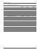
Illustrated Parts Catalog Table 1-2: System Components Spare Parts List continued Item Description Assembly Number Spare Part Number Customer Self Repair Mass storage devices 10 IDE CD-ROM drive (48X) 266072-001 288894-005 Yes 11 Non-hot-plug SCSI hard drive, 36 GB 357014-001 372659-005 Yes 12 Non-hot-plug SATA hard drive, 80 GB 332649-003 373311-005 Yes 377580-001 382097-001 Yes Yes Power 13 350-W power supply unit with cable assembly Cable assembly 14 IDE CD-ROM drive cable ass
Illustrated Parts Catalog HP Contact Information For the name of the nearest HP authorized reseller: • In the United States, call 1-800-345-1518. • In Canada, call 1-800-263-5868. • In other locations, refer to the HP website at http://www.hp.com/. For HP technical support: • In North America: — Call 1-800-HP-INVENT (1-800-474-6836). This service is available 24 hours a day, 7 days a week. For continuous quality improvement, calls may be recorded or monitored.
2 Removal and Replacement Procedures This chapter provides subassembly/module-level removal and replacement procedures for the HP ProLiant ML110 Generation 2 server. Review the specifications of a new component before installing it to make sure it is compatible with the server. When you integrate new components into the system, record its model and serial number, and any other pertinent information for future reference.
Removal and Replacement Procedures Non-hot-plug Device If the device is non-hot-plug, the server must be powered down. Non-hot-plug devices in the server include the processor, all boards, memory modules, fans, PCI option cards, and non-hot-plug disk drives. Electrostatic Discharge Information ESD can damage static-sensitive devices or microcircuitry. Proper packaging and grounding techniques are necessary precautions to prevent damage.
Removal and Replacement Procedures This symbol indicates the presence of electric shock hazards. The area contains no user or field serviceable parts. Do not open for any reason. WARNING: To reduce the risk of injury from electric shock hazards, do not open this enclosure. This symbol on an RJ-45 receptacle indicates a network interface connection. WARNING: To reduce the risk of electric shock, fire, or damage to the equipment, do not plug telephone or telecommunications connectors into this receptacle.
Removal and Replacement Procedures 3. Disconnect telecommunication cables to avoid exposure to shock hazard from ringing voltages. 4. Open the server according to the instructions described in the “System Covers” section in this chapter. 5. Follow the ESD precautions listed previously in this chapter when handling a server component. Post-installation Instructions Observe the following items after installing or removing a server component: 1.
Removal and Replacement Procedures WARNING: To reduce the risk of personal injury from hot surfaces, allow the internal system components to cool before touching them. CAUTION: Protect the server from power fluctuations and temporary interruptions with a regulating uninterruptible power supply (UPS). This device protects the hardware from damage caused by power surges and voltage spikes, and keeps the system in operation during a power failure.
Removal and Replacement Procedures c. Pull the panel upward to remove it from the chassis. Figure 2-1: Removing the access panel 3. Place the access panel in a safe place for reinstallation later. After completing any removal or replacement procedure, replace the access panel. Follow the steps below: 1. If you have been installing accessories or servicing the server, return the server to its normal upright position. 2. Perform steps 1 through 4 of the post-installation instructions. 3.
Removal and Replacement Procedures Figure 2-2: Reinstalling the access panel 4. Perform steps 5 through 7 of the post-installation instructions. Front Bezel The front bezel must be removed to access the hard disk drive (HDD) cage. To remove the front bezel: 1. Remove the access panel. 2. Remove the front bezel: a. Press the two plastic retention clips on the bottom of the bezel upward to release them from their tabs on the inside of the chassis. b.
Removal and Replacement Procedures Figure 2-3: Removing the front bezel 3. Place the front bezel in a safe place for reinstallation later. To replace the front bezel, follow the steps below: 1. Position the bezel so the two mounting tabs are aligned with their notch on the front panel, then insert the tabs into their notch. 2. Align then insert the two plastic retention clips to their notch on the front panel, and then press them firmly until they snap into place.
Removal and Replacement Procedures Air Baffle Remove the air baffle to better access the system fan and the system board components.
Removal and Replacement Procedures Drive Bay Configuration The server supports a maximum of seven internal drives. The upper drive bay is for removable media devices, while the lower drive bay is for an HDD cage. The upper drive bay contains a one-half height IDE CD-ROM drive and two empty full-height drive bays. The lower drive bay can accommodate a hot-plug or a non-hot-plug HDD cage.
Removal and Replacement Procedures IDE CD-ROM Drive Cable Routing Figure 2-8: IDE CD-ROM drive cable routing Item Description 1 IDE CD-ROM drive power cable 2 IDE CD-ROM drive data cable Optional Media Drive Cable Routing Figure 2-9: Optional media drive cable routing Item Description 1 Optional media drive power cable 2 Optional media drive data cable HP ProLiant ML110 Generation 2 Server Maintenance and Service Guide 2-11
Removal and Replacement Procedures Non-hot-plug SCSI/SATA HDD Cable Routing Figure 2-10: Non-hot-plug SCSI HDD cable routing No. Description 1 SCSI power cable 2 SCSI data cable Figure 2-11: Non-hot-plug SATA HDD cable routing 2-12 No.
Removal and Replacement Procedures Hot-plug SATA HDD Cable Routing Figure 2-12: Hot-plug SATA HDD cage cable routing No. Description 1 SATA power cables 2 4-in-1 SATA data cables 3 SATA LED cable Figure 2-13: Hot-plug SATA HDD backplane board No.
Removal and Replacement Procedures Figure 2-14: Hot-plug SATA HDD RAID card No. Connector Description 1 PORT0 – PORT5 SATA HD connectors (connects to the HD connectors on the backplane board) 2 I2C SATA I2C LED connector (connects to CN3 on the backplane board) 3 ACT_LED SATA HD active LED connector IDE CD-ROM Drive To replace the IDE CD-ROM drive: 1. Perform steps 1-3 of the pre-installation instructions. 2. Remove the access panel. 3. Remove the front bezel. 4.
Removal and Replacement Procedures Figure 2-15: Removing the IDE CD-ROM drive 5. Place the old CD-ROM on a static-dissipating work surface or inside an anti-static bag. 6. Remove the new CD-ROM from its protective packaging. 7. Check that the IDE jumper on the rear section of the CD-ROM drive is set to Cable-Select mode. 8. Install the new CD-ROM drive: a.
Removal and Replacement Procedures Figure 2-16: Installing the IDE CD-ROM drive 9. Observe the post-installation procedures. Optional Media Device The two full-height drive bays may be used for a DVD-ROM drive, tape drive, non-hot-plug hard drive, any SCSI device or a 2-bay SCSI drive cage, including a DLT tape drive. A DLT tape drive or the 2-bay SCSI drive cage requires both empty full-height drive bays. To install an optional media drive: 1.
Removal and Replacement Procedures Figure 2-17: Preparing the drive bay for installation 6. Prepare the new drive for installation. Refer to the documentation that came with the drive for related installation procedures. 7. Install the new drive: a. Guide the new drive into the selected common bay, with the cable connectors of the drive facing the rear of the chassis, then push the drive all the way into the chassis until the mounting holes are aligned. b. Press the retaining lever downward. c.
Removal and Replacement Procedures HDD Cage The lower drive bay on the front panel accommodates an HDD cage for installation of up to four additional hard drives. The hot-plug HDD cage model supports SATA drives, while the non-hot-plug one supports both SATA and SCSI drives. To install an HDD cage: 1. Perform steps 1 through 3 of the pre-installation instructions. 2. Remove the access panel. 3. Remove the front bezel. 4. Install the HDD cage: a.
Removal and Replacement Procedures Figure 2-20: Installing a non-hot-plug HDD cage (SATA) For the hot-plug HDD cage, connect the SATA power, data, and LED cables to their corresponding backplane board connectors. Refer to Figure 2-13 for an illustration of the backplane board. Make sure that the other end of the power cable is connected to the PSU, and the other end of the data and LED cables are connected to their corresponding connector on the SATA RAID card.
Removal and Replacement Procedures Non-hot-plug HDD Cage To install a SCSI drive in a non-hot-plug HDD cage: 1. Perform steps 1 through 3 of the pre-installation instructions. 2. Remove the access panel. 3. Remove the front bezel. 4. Remove the non-hot-plug HDD cage: Step (a) below assumes that a drive is currently installed in the cage. If the cage is empty, go directly to step (b). a. Disconnect the power and data cables from the rear of the drive.
Removal and Replacement Procedures 6. Install the new SCSI hard disk into the cage: a. Slide the new hard disk into the selected bay. b. If you are installing the new hard disk in a previously occupied drive bay, use the screws you removed from that old drive to secure the new drive. If you are installing the new hard disk in an empty drive bay, use the four screws you removed earlier from the side of the chassis to secure the new drive.
Removal and Replacement Procedures Figure 2-24: Removing the non-hot-plug HDD cage for SATA drive installation 5. Select a drive bay in the cage where you want to install the new SATA hard disk. If you going to install the new hard disk in a previously occupied drive bay, pull out the installed drive by removing the four screws securing the old drive to the cage, before sliding the drive out of the cage. You will be reusing these screws when you install the new hard disk.
Removal and Replacement Procedures 7. Reinstall the HDD cage into the chassis following the procedures described in step 4 of the “To install an HDD cage” section. 8. Observe the post-installation procedures. Hot-plug HDD Cage To install a SATA drive in a hot-plug HDD cage: 1. Remove the front bezel. 2. Select a drive bay in the cage where you want to install the SATA new hard disk. If the desired drive bay is occupied, remove the currently installed drive from the cage. Proceed to step 3 for procedures.
Removal and Replacement Procedures 4. Install the SATA new hard disk: a. Slide the new drive into the selected drive bay. b. Close the ejector lever to secure the new drive in the cage. Figure 2-27: Installing a SATA hard disk in the hot-plug HDD cage 5. Reinstall the front bezel. If you need to remove the hot-plug HDD cage from the chassis, follow the steps below: CAUTION: Failure to remove hard drives from the hot-plug HDD cage prior to removing the cage from the chassis may cause damage to the drives.
Removal and Replacement Procedures c. Gently slide out the cage from the chassis. Figure 2-28: Removing the hot-plug HDD cage System Board Components Refer to the following sections for instructions on how to remove or replace the processor, the memory modules, the expansion cards, and the system battery. Processor The server LGA775 processor socket supports Intel Pentium 4 processors. Figure 2-29: LGA775 processor socket To replace the processor: 1.
Removal and Replacement Procedures 4. Pull out the air baffle for better access to the processor socket (U10). 5. If necessary, remove any accessory boards or cables that prevent access to the processor socket. 6. Remove the heatsink-cooling fan (HSF) assembly: a. Disconnect the processor fan cable from the connector on the system board (CN7). b. Twist the mounting pins clockwise to loosen them up. c. Once you have loosened all four mounting pins, lift the HSF away from the system board.
Removal and Replacement Procedures Figure 2-31: Removing the processor 8. Place the old processor on a static-dissipating work surface or inside an anti-static bag. To allow the heatsink to draw away as much heat as possible from the processor base, it is required there be a tight connection between the contact surfaces—the heatsink base and the top side of the processor. To ensure this, it is required that a thermal grease compound be applied.
Removal and Replacement Procedures CAUTION: Applying too much grease will cause a gap between the contact surfaces. This means that the heatsink is not even in direct contact with the processor, and therefore its capacity to draw out heat is greatly reduced. Applying too much grease could also make the grease squish out from the sides and go all over the processor pins or to the system board base once the heatsink is installed. This may cause electrical shorts that can damage your system. 10.
Removal and Replacement Procedures 11. Replace the heatsink-cooling fan assembly: a. Align the HSF mounting pins to the system board holes and press it down until you hear a click. b. Twist the mounting pins counter-clockwise to secure the HSF’s connection to the system board. c. Connect the processor fan cable to its connector on the system board (CN7).
Removal and Replacement Procedures Memory The HP ProLiant ML110 Generation 2 server has four DIMM slots that support up to 4 GB maximum system memory (1 GB in each of the four DIMM slots). Figure 2-34: DIMM slots Guidelines for Installing Memory Modules The following guidelines must be followed when memory modules are being added or replaced: 2-30 • Use only DDR1-400 unbuffered ECC and non-ECC DIMMs in 256-MB, 512-MB, or 1-GB configuration.
Removal and Replacement Procedures To remove a memory module: 1. Perform steps 1 through 3 of the pre-installation instructions. 2. Remove the access panel. 3. Lay the server on its side (components showing). 4. Remove the air baffle for better access to the DIMM slots (DIMM1 to DIMM4). 5. If necessary, remove any accessory boards or cables that prevent access to the DIMM slots. 6. Locate the memory module you want to remove. 7. Remove the selected memory module: a.
Removal and Replacement Procedures b. Firmly press the holding clips inward to secure the memory module in place. If the holding clips do not close, the module is not inserted correctly. Figure 2-36: Installing a memory module 4. Observe the post-installation procedures. Expansion Cards The HP ProLiant server supports five PCI slots with three separate bus channels: • Three 64-bit/100-MHz, 3.
Removal and Replacement Procedures To install an expansion card: 1. Perform steps 1 through 3 of the pre-installation instructions. 2. Remove the access panel. 3. Remove the air baffle for better access to the PCI slots (PCI1 to PCI5). 4. If necessary, remove any accessory boards or cables that prevent access to the PCI slots. 5. Locate an empty PCI slot on the system board. 6. Prepare the selected PCI slot for installation: a. Press the retention clip of the slot cover opposite the selected PCI slot. b.
Removal and Replacement Procedures 8. Install the expansion card: a. Slide the expansion card into the selected slot and press it down to seat it properly. b. Firmly press the retention clip until it snaps into place. Figure 2-39: Installing an expansion card 9. Connect the necessary cable to the card. 10. Observe the post-installation procedures. System Battery The HP ProLiant server uses nonvolatile memory that requires a battery to retain system information when power is removed.
Removal and Replacement Procedures If the server no longer automatically displays the correct date and time, the system battery that provides power to the real-time clock may need to be replaced. Under normal use, battery life is 5 to 10 years. WARNING: Note the following reminders when replacing the system battery. • Replace the battery with the same type as the battery recommended by HP. Use of another battery may present a risk of fire or explosion.
Removal and Replacement Procedures Figure 2-41: Replacing the battery 6. Observe the post-installation procedures. Power Supply Unit (PSU) Located on the rear panel of the server is a single standard autoranging 350-watts PSU with PFC (power factor correction) function. WARNING: Take note of the following reminders to reduce the risk of personal injury from electric shock hazards and/or damage to the equipment.
Removal and Replacement Procedures c. Gently slide the PSU out of the chassis. Figure 2-42: Removing the PSU 5. Install a new PSU: Perform step (a) and (b) simultaneously. a. Align the new PSU to the support ledges inside the chassis. b. Secure the PSU in place using the four screws you removed earlier. c. Reconnect the processor and system board power cables to their connectors (PWRCON1 and PWRCON2), then connect the power cables of all installed drives to the PSU. Figure 2-43: Installing a PSU 6.
Removal and Replacement Procedures System Fan A new system fan can be installed to allow the server to operate properly in case the default system fan becomes defective. To replace the system fan: 1. Perform steps 1 through 3 of the pre-installation instructions. 2. Remove the access panel. 3. Remove the air baffle. 4. Remove the default system fan: WARNING: Be sure to support the system fan with your hands when removing it from the chassis.
Removal and Replacement Procedures 5. Detach the old fan from its frame: a. Unclasp the four retention latches on the frame. b. Pull the fan away from its frame. Figure 2-45: Removing a system fan from its frame 6. Install the new fan to its frame by aligning the pegs on the frame to their corresponding notch on the fan, and then firmly press the two together until the retention latches snap into place.
Removal and Replacement Procedures 7. Install a new system fan: a. Insert the tabs on the system fan frame to their chassis notch. b. Slide the system fan downward to secure it to the chassis. c. Connect the system fan cable to its connector (CN10) on the system board. Figure 2-47: Installing a system fan on the chassis 8. Observe the post-installation procedures.
3 Diagnostic Tools This chapter describes the system diagnostic tools available for the HP ProLiant ML110 Generation 2 server. It also provides a comprehensive list of POST-related messages and their meanings. PhoenixBIOS Software PhoenixBIOS software is a ROM BIOS-based diagnostic tool that monitors system activity and performs constant hardware testing to ensure proper system operation. ROM BIOS is a set of programs permanently stored in an EEPROM chipset (U34) located on the system board.
Diagnostic Tools PhoenixBIOS Setup Utility NOTE: For ease of reading, PhoenixBIOS Setup Utility will be simply referred to as “Setup” or “Setup Utility” in this guide. NOTE: The screenshots used in this guide display default system values. These values may not be the same those in your server. PhoenixBIOS Setup Utility is a hardware configuration program built into your system's Basic Input/Output System (BIOS).
Diagnostic Tools Accessing the Setup Utility 1. Turn on the monitor and the server. If the server is already turned on, save your data and exit all open applications, then restart the server. 2. During POST, press F10. If you fail to press F10 before POST is completed, you will need to restart the server. The first page to be displayed will be the Main menu showing the Setup Utility’s menu bar. Use the left (←) and right (→) arrow keys to move between selections on the menu bar.
Diagnostic Tools Navigating Through the Setup Utility Use the keys listed in the legend bar on the bottom of the Setup screen to work your way through the various menu and submenu screens of the Setup Utility. Table 3-1 lists these legend keys and their respective functions. Table 3-1: Setup Utility’s Navigation Keys Key Function ← and → To move between selections on the menu bar. ↑ and ↓ To move the cursor to the field you want. The currently selected field will be highlighted.
Diagnostic Tools Setup Utility Primary Menus The Setup Utility’s menu bar displays the six primary menu selections. Table 3-2 lists these menus and their corresponding functions. Table 3-2: Setup Utility's Primary Menus Menu Function Main Use this menu to: Advanced • Set the system time and date. • Select the type of diskette drive type. • Configure drive settings for available IDE and SATA devices. • Select which options to run during system boot-up.
Diagnostic Tools Table 3-2: Setup Utility's Primary Menus continued Menu Function Security Use this menu to safeguard and protect the system from unauthorized use by setting up access passwords. For more information on using this menu, go to the “System Passwords” section in this chapter. Power Use this menu to: Boot • Set the mode of operation if an AC power loss occurs. • Enable or disable the PCI PME power-up function.
Diagnostic Tools System Summary Screen The System Summary Screen displays basic and important information about the current server configuration and is necessary for troubleshooting and may be required when asking for technical support.
Diagnostic Tools The System Summary Screen is displayed briefly at the end of POST. Figure 3-2: System Summary Screen 6. Press the Pause/Break key to continue displaying the screen until another key is pressed. 7. Press any key to continue with the system bootup. System Passwords The Security menu lets you set system passwords that would provide different levels of protection for the server.
Diagnostic Tools To set a system password: NOTE: A Supervisor password should be set first before a User password can be defined. 1. In the Security menu screen, select a set password field—Set User Password or Set Supervisor Password, then press Enter. Figure 3-3: Setup window for setting a system password 2. Type a new password in the password box. The password may consist of up to eight alphanumeric characters (A-Z, a-z, 0-9). 3. Retype the password to verify the first entry, then press Enter. 4.
Diagnostic Tools To change a system password: 1. In the Security menu screen, select a set password field—Set User Password or Set Supervisor Password, then press Enter. Figure 3-4: Setup window for changing a system password 2. Type the original password in the password box. 3. Type a new password then press Enter. 4. Retype the new password to verify the first entry then press Enter again. 5. Press F10 to save the password and close the Setup Utility. To remove a system password: 1.
Diagnostic Tools To reset a system password: If you have forgotten the user password or the supervisor password, the server will continue to function normally but you will not be able to access the Setup Utility. If you have enabled the Password on Boot field and have forgotten both the user password and the supervisor password, you will not be able to reboot the server. If you have forgotten the user password, you can use the supervisor password to reset it.
Diagnostic Tools Loading System Defaults If your system fails after you make changes in the Setup menus, reboot the server, enter Setup and load the system default settings to correct the error. These default settings have been selected to optimize your server’s performance. To load the system defaults: 1. Reboot the server in a normal manner. 2. During POST, press F10 to access the Setup Utility. 3. Press F9 to load the default values. 4. Press F10 to save the changes you made and close the Setup Utility.
Diagnostic Tools Setting Hardware Protection You have the option to lock and unlock some of the I/O ports available on the server. 1. In the Advanced menu screen, select the Hardware Protection field, then press Enter. Figure 3-5: Setup Utility’s Hardware Protection window 2. Select the hardware item you want to lock. Options include: • Serial port • Parallel port • USB ports 3. Press the (+) or (-) key to set the selected hardware to Lock. 4.
Diagnostic Tools Power-On Self Test (POST) When the server boots up, a series of tests are displayed on the screen. This is referred to as Power–On Self–Test or POST. POST is a series of diagnostic tests that checks firmware and assemblies to ensure that the server is properly functioning. This diagnostic function automatically runs each time the server is powered on.
Diagnostic Tools Table 3-3 lists down the most common POST error messages with their corresponding troubleshooting recommendation. It is recommended that you correct the error before proceeding, even if the server appears to boot successfully. If your system displays one of the messages marked below with an asterisk (*), write down the code and message and contact your HP Customer Support provider. When no POST error message is displayed but the server stops during POST, listen for beep codes.
Diagnostic Tools Table 3-3: POST Error Messages continued Error code Error message Description/corrective action 0250 System battery is dead Replace and run SETUP The CMOS clock battery indicator shows the system battery is dead. 0251 System CMOS checksum bad - Default configuration used 1. Replace the system battery. Go to the “System Battery” section of Chapter 2. 2. Run Setup to reconfigure the system.
Diagnostic Tools Table 3-3: POST Error Messages continued Error code Error message Description/corrective action 02D0 System cache error - Cache disabled * RAM cache failed and BIOS disabled the cache. Invalid System Configuration Data Problem with the CMOS data. You can do any of the following: • Load the system default values. Refer to the “Loading System Defaults” section in this chapter for details. • Access Setup and enter your own custom values.
Diagnostic Tools POST-related Troubleshooting Perform the following procedures when POST fails to run or display error messages or emit beep codes. If the POST failure is during a routine bootup, check the following: • All external cables and power cables should be firmly plugged in. • The power outlet to which the server is connected is working. • The server and monitor are both turned on. The bicolor status LED indicator on the front panel must be lit up green.
Diagnostic Tools Diagnostics for Windows Diagnostics for Windows provides an easy-to-use hardware diagnostic for server verification and rapid troubleshooting. This utility is installed from the HP ProLiant ML110 Generation 2 Server Support CD, and run under Microsoft Windows. For instructions on installation and use, refer to the README file located inside the Diagnostics for Windows folder in the Support CD.
4 Connectors, Switches, and LEDs This chapter contains illustrations and tables identifying and describing the connectors, switches, buttons, and LED indicators located on the front panel, rear panel, system board and hard drives of the HP ProLiant ML110 Generation 2 server. Connectors and Components This section contains illustrations and tables identifying connectors and components on the front and rear panels of the server, as well as those located on the system board.
Connectors, Switches, and LEDs Table 4-1: Front Panel Components Item Icon Component 1 IDE CD-ROM drive 2 IDE CD-ROM drive mechanical eject hole 3 IDE CD-ROM drive eject button 4 IDE CD-ROM drive activity LED indicator (amber) 5 Full-height common bays 6 Power/system health LED indicator (bicolor: green/amber) 7 Power button 8 • Powers up the server. • Places the server in standby mode. • Powers down the server.
Connectors, Switches, and LEDs Rear Panel Components Figure 4-2 and Table 4-2 show and describe the components on the rear panel of the server. Figure 4-2: Rear panel components Table 4-2: Rear Panel Components Item Icon Component 1 PS/2 mouse port (green) 2 PS/2 keyboard port (purple) 3 Serial port (teal) 4 Parallel port (burgundy) 5 Video port (blue) 6 Rear USB 2.
Connectors, Switches, and LEDs I/O Device Connection The color-coded I/O ports on the rear panel are each marked with icons that indicate the kind of devices that can be connected to them. Figure 4-3: Connecting I/O devices System Board Components Figure 4-4 and Table 4-3 show and describe the components on the system board.
Connectors, Switches, and LEDs Table 4-3: System Board Components Item Component Code Component 1 CN1 Top: PS/2 mouse port Bottom: PS/2 keyboard port 2 CN2 Top: Parallel port Left: Video port Right: Serial port 3 CN5 Rear USB 2.0 ports (two) 4 CN6 LAN port (RJ-45) 5 CN7 3-pin processor fan connector 6 CN10 3-pin system fan connector (rear) 7 PCI1 – PCI3 64-bit/100-MHz, 3.
Connectors, Switches, and LEDs Table 4-3: System Board Components continued Item Component Code Component 26 IDE1 IDE connector 27 SW1 System configuration switch (dip switch) 28 U46 Intel 82801FR I/O controller hub 6 R (ICH6R) chipset (south bridge) 29 JP1 PCI-X bus speed jumper Jumper setting: • 1-2 – 133 MHz PCI-X bus (default) • 2-3 – 100 MHz PCI-X bus 30 BT1 Maxell CR2032 H 3 V internal lithium system battery 31 U16 Intel 6702 PXH-V (PCI-X hub) chipset (PCI bridge) 32 U9 Inte
Connectors, Switches, and LEDs Table 4-4: System Configuration Switch Settings Switch Status Function SW1-1 On Enable FWH (firmware hub) protection by software Off No FWH protection On Clear password enabled Off Clear password disabled On Boot block enabled Off Normal boot On Clear CMOS enabled Off Clear CMOS disabled SW1-2 SW1-3 SW1-4 Status LED Indicators This section contains illustrations and descriptions of internal and external status LED indicators located on the: • Front pane
Connectors, Switches, and LEDs IDE CD-ROM Drive Activity LED Indicator The IDE CD-ROM drive has an activity indicator that shows when a compact disc (audio, video, or data disc) is being read Figure 4-6: IDE CD-ROM drive activity LED indicator Activity states for the IDE CD-ROM drive are as follows: • Flashing amber – Ongoing drive activity • Off – No drive activity Power/System Health LED Indicator The power status and health condition of the server is indicated by the bicolor LED found on the front
Connectors, Switches, and LEDs Table 4-5: Power/System Health LED Indicator Status Function Status Description Power status indicator Steady green The server is operating normally. Flashing green The server is in standby mode (auxiliary power present). Off The server is powered off (AC power disconnected). Steady amber A pre-failure system threshold has been breached.
Connectors, Switches, and LEDs Hard Drive LED Indicators for Hot-plug SATA Drives A hot-plug SATA device installed in the server has its own set of LED indicators located on its carrier. Figure 4-9 and Table 4-6 show and describe these LEDs.
Connectors, Switches, and LEDs Table 4-6: Hot-plug SATA Drive LED Indicators Status continued Item Component Status Description Flashing green during a drive activity (if command is outstanding continually the indicator is forced to flash at 4 Hz 50% duty cycle instead of solid off) • Drive is currently performing an I/O activity • Drive is a member of a RAID volume • Drive is not in a replacement or failed state for any volumes that it is a member of (drive is online) • Drive is not rebuilding
Connectors, Switches, and LEDs S.M.A.R.T. Function Self-Monitoring Analysis and Reporting Technology or S.M.A.R.T. is an interface function between the system BIOS and the SATA hard drive. When enabled BIOS receives information from the SATA drive that allows the former to send a warning message of possible hard drive failure. To activate the S.M.A.R.T. function: 1. Turn on the monitor and the server.
Connectors, Switches, and LEDs Table 4-7: LAN LED Indicators Status Item Component Status Description 1 LAN activity/link status LED indicator Steady green An active network link exists. Flashing green An ongoing network data activity exists. Off The server is off-line Steady green The LAN connection is using a GbE link. Steady amber The LAN connection is using a 100 Mbps link. Off The LAN connection is using a 10 Mbps link.
5 Physical and Operating Specifications This chapter provides physical and operating specifications for the HP ProLiant ML110 Generation 2 server.
Physical and Operating Specifications System Unit Table 5-1: Hardware Specifications Item Component Processor socket Intel LGA775 socket platform Processor support Intel Celeron D Intel Pentium 4 Core logic chipset Intel E7220 (north bridge) Intel ICH6R (south bridge) Intel 6702 PXH-V (PCI bridge) Super I/O chipset SMSC LPC47M192 Hardware monitoring chipset Winbond W83792AD Gigabit Ethernet controller Intel GD8254IPI Memory controller Integrated in the Intel E7220 chipset Storage controller
Physical and Operating Specifications Table 5-1: Hardware Specifications continued Item Component Status LED indicators Front panel Rear panel System board • IDE CD-ROM drive activity • Power/system health status • Hard drive activity • LAN activity/link status • LAN network speed • Standby mode • Power status Power supply unit (PSU) Delta SSI DPS (350 watts) System management function IPMI 1.
Physical and Operating Specifications Table 5-3: Physical Dimensions Item Description System board platform ATX (Advanced Technology eXtended) System board dimensions Length 305 mm (12 in) Width 244 mm (9.6 in) Server dimensions Height • Without foot stands – 430 mm (16.9 in) • With foot stands – 440 mm (17.3 in) Width 200 mm (7.9 in) Length • Without bezel – 500 mm (19.7 in) • With bezel – 535 mm (21.1 in) • Basic configuration (excludes keyboard and monitor) – approximately 14.
Physical and Operating Specifications Table 5-4: Environmental Specifications continued Item Description Altitude Operating 0 to 3,048 m (0 to 10,000 ft) Non-operating 0 to 9,144 m (0 to 30,000 ft) Thermal output (maximum operating) 1907 BTU/hr Acoustic emissions Normal configuration LpA: <38 dBA, operating at room temperature Maximum configuration LpA: <70 dBA Table 5-5: Power Supply Requirements Item Description Model Delta SSI DPS Input type AC Operating power 350-W at 25°C; 320-W at
Physical and Operating Specifications Processor The server’s Intel LGA775 processor socket supports Celeron D and Pentium 4 processors employing the 90 nm process technology. Table 5-7: Intel Celeron D Processor Specifications Operating Frequency FSB Speed On-die L2 Cache Voltage Range Package 3.06 GHz 533 MHz 256 MB 1.25 – 1.4 FC-LGA4 2.93 GHz 533 MHz 256 MB 1.25 – 1.4 FC-LGA4 2.8 GHz 533 MHz 256 MB 1.25 – 1.4 FC-LGA4 2.66 GHz 533 MHz 256 MB 1.25 – 1.4 FC-LGA4 2.
Physical and Operating Specifications Table 5-9: IDE CD-ROM Drive Specifications continued Item Description Supported disc formats • Mixed mode (audio and data combined) • CD-DA, mode 1(basic format), M ode 2, Form 1 and Form 2 • Photo-CD (multi-session), CD-XA • CD-I, CD-Plus/CD-Extra, CD-RW Rotational speed 20x to 48x Data capacity Mode1 and Mode 2, Form 1 2,048 bytes/block Mode 2 2,340/2,336 bytes per block Mode 2, Form 2 2,332 bytes/block CD-DA 2,352 bytes/block Data buffer capacit
Physical and Operating Specifications Non-hot-plug SCSI Hard Drive Table 5-10: Non-hot plug SCSI Hard Drive Specifications Item Description Model Fujitsu Allegro 8LX Capacity 36-GB Dimensions Height 25.4 mm (1.0 in) Width 101.6 mm (4.0 in) Depth 146.0 mm (5.8 in) Weight (max. population) .68 kg (1.
Physical and Operating Specifications SCSI Storage Controller Table 5-12: SCSI Storage Controller Specifications Item Description Model LSI Logic Ultra320 SCSI Host Adapter Processor LSI LSI53C1020 Form factor Low-profile PCI-X Interface type PCI-X/133 MHz Controller interface Ultra320 SCSI Dimensions Height 63.5 mm (2.5 in) Depth 170.2 mm (6.
Physical and Operating Specifications SATA RAID Controller Table 5-13: SATA RAID Controller Specifications Item Description Model Adaptec AAR-2610SA Form factor Half-size, full height PCI Features • Intel 80302 Intelligent I/O processor • Three (3) Silicon Image SI3512 dual SATA 1.
Index A AC power connector 4-3 disconnecting, warning 2-4 power-down procedures 2-4 access panel part number 1-2 reinstalling 2-6 removing 2-5 acoustic emissions, environmental specifications 5-5 air baffle part number 1-2 reinstalling 2-9 removing 2-9 altitude, environmental specifications 5-5 ATX Advanced Technology eXtended See system board, platform B Basic Input/Output System See PhoenixBIOS Setup Utility battery location 2-34 POST error message 3-16 replacement warnings 2-35 replacing 2-35 boot bloc
Index drive bay configuration HDD cage 2-18 IDE CD-ROM drive 2-14 optional media device 2-16 overview 2-10 E EEPROM location 4-5 PhoenixBIOS software 3-1 electric shock symbol 2-2, 2-3 warning 2-2 Electrically Erasable Programmable Read-Only Memory See EEPROM electrostatic discharge See ESD environmental specifications acoustic emissions 5-5 altitude 5-5 relative humidity 5-4 temperature 5-4 thermal output 5-5 ESCD clearing configuration data 3-5 definition 3-5 ESD damage precautions 2-2 work area recomme
Index height with foot stands 5-4 without foot stands 5-4 hot surface symbol 2-3 warning 2-5 HP authorized reseller 1-5 contact information 1-5 technical support 1-5 technical support requirements 1-5 HSF part number 1-3 removing 2-26 replacing 2-29 system board connector 4-5 HT See Hyper-Threading technology Hyper-Threading technology definition 3-5 enabling 3-5 I I/O ports See input/output ports I/O subsystem 5-2 I2C LED cable, part number 1-4 IDE CD-ROM drive activity indicator 4-8 cable assembly, part
Index thermal grease 1-4 N network boot 3-14 network operating system See NOS support non-hot-plug device 2-2 NOS support 5-3 O onboard controllers enabling or disabling 3-5 LAN 5-2 memory controller 5-2 storage controller 5-2 VGA 5-2 operating system, POST error message 3-17 optional media device cable routing 2-11 installing 2-16 P parallel port location 4-3 locking 3-13 part numbers access panel 1-2 air baffle 1-2 boards 1-3 feet 1-2 front bezel 1-2 front panel board cable assembly 1-4 front USB port
Index physical dimensions 5-4 server 5-4 system board 5-4 plastics kit, part number 1-2 POST beep codes 3-17 error indicators 3-14 errors messages 3-15 network boot 3-14 non-fatal errors 3-14 overview 3-14 running 3-14 terminal error 3-17 troubleshooting 3-18 power button 4-2 power cord, electric shock warning 2-4 power fluctuations, caution 2-5 power sources symbol 2-3 power status indicator 4-9 power supply cable socket 4-3 power supply requirements input 5-5 input range 5-5 inrush type 5-5 maximum curre
Index server boards illustration SATA backplane board 2-13 SATA RAID card 2-14 system board 4-4 server dimensions height 5-4 length 5-4 width 5-4 software specifications NOS 5-3 system diagnostics 5-3 specifications environmental 5-4 hardware 5-2 hot-plug SATA hard drive 5-8 IDE CD-ROM drive 5-6 non-hot-plug SCSI hard drive 5-8 physical dimensions 5-4 power supply requirements 5-5 processor 5-6 SATA RAID controller 5-10 SCSI storage controller 5-9 software 5-3 system unit 5-2 standby mode activating 2-5 ef
Index temperature, environmental specifications 5-4 thermal grease caution 2-28 part number 1-4 recommendation 2-27 thermal output, environmental specifications 5-5 thermal patch 2-26 thermal solution 5-3 U uninterruptible power supply See UPS UPS 2-5 USB ports cable assembly, part number 1-4 front 4-2 locking 3-13 rear 4-3 user password 3-8 V VGA controller 5-2 video port 4-3 W warnings battery replacement 2-35 component-level repairs 2-1 hot surface 2-5 improper repairs 2-1 personal injury 2-5 power c