HP ProLiant ML110 G7 Server User Guide Abstract This document is for the person who installs, administers, and troubleshoots servers and storage systems. This document is intended for experienced IT professionals or end-users with no or prior hardware setup experience. HP assumes you are qualified in the servicing of computer equipment and trained in recognizing hazards in products with hazardous energy levels.
© Copyright 2011, 2013 Hewlett-Packard Development Company, L.P. The information contained herein is subject to change without notice. The only warranties for HP products and services are set forth in the express warranty statements accompanying such products and services. Nothing herein should be construed as constituting an additional warranty. HP shall not be liable for technical or editorial errors or omissions contained herein. Microsoft®, and Windows® are U.S.
Contents Component identification ............................................................................................................... 7 Front panel components ............................................................................................................................. 7 Front panel LEDs and buttons ............................................................................................................ 7 Rear panel components ...................................................
Drive installation guidelines ............................................................................................................ 30 Installing a drive ............................................................................................................................ 30 Drive cage options .................................................................................................................................. 32 Four-bay LFF hot-plug drive cage option...............................
HP Insight Remote Support software ................................................................................................. 72 Keeping the system current ....................................................................................................................... 73 Drivers ......................................................................................................................................... 73 Version control .............................................................
Contents 6
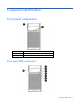
Component identification Front panel components Item Description 1 Media drive bay 2 USB connectors (4) Front panel LEDs and buttons Component identification 7
Item Description Status 1 System health LED Green = Normal Amber = System degraded Red = System critical 2 NIC 1 link/activity LED Green = Network link Flashing green = Network link and activity Off = No link to network (If the power is off, view the rear panel NIC LEDs for status.
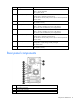
4 Slot 1 PCIe2x16 (16, 8, 4, 1) 5 Slot 2 PCIe2x8 (4, 1) 6 Slot 3 PCIe2x8 (4, 1) 7 Slot 4 PCIe2x4 (1) 8 USB connectors (4) 9 HP dedicated iLO management port (option) 10 UID button/LED 11 10/100/1000 NIC1 connector/shared iLO management port 12 10/100/1000 NIC2 connector 13 Video connector 14 Serial connector Rear panel LEDs and buttons Item Description Status 1 UID LED/button Flashing blue = Activated Off = System being managed remotely/deactivated 2 HP dedicated iLO management
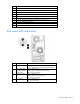
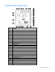
System board components Item Description 1 Dedicated iLO management module connector 2 System maintenance switch 3 RPS connector (1x5 pin) 4 Front system fan connector (2x3 pin) 5 Processor socket 6 DIMM slots (4) 7 24-pin power supply connector 8 Processor-heatsink fan assembly connector (2x3 pin) 9 Rear system fan connector (2x3 pin) 10 RPS connector (2x8 pin) 11 Internal USB connector 12 System battery 13 I2C cable connector 14 SATA connectors (2) 15 SMB bus connector 16
Item Description 27 Rear USB connectors (4) 28 NMI header DIMM slot locations DIMM slots are numbered sequentially (1 through 4) for the processor.
CAUTION: Clearing CMOS and/or NVRAM deletes configuration information. Be sure to properly configure the server or data loss could occur. System board LEDs Item LED description Status 1 Power supply 1 failure Red = Power supply 1 failed Off = Normal 2 Power supply 2 (redundant) failure Red = Power supply 2 failed Off = Normal NMI functionality An NMI crash dump enables you to create crash dump files when a system is hung and not responding to traditional debug mechanisms.
SAS and SATA drive numbering • Four-bay LFF drive model • Eight-bay SFF drive model Component identification 13
SAS and SATA drive LEDs Item Description 1 Fault/UID LED (amber/blue) 2 Online LED (green) SAS and SATA drive LED combinations Online/activity LED (green) Fault/UID LED (amber/blue) Interpretation On, off, or flashing Alternating amber and The drive has failed, or a predictive failure alert has been blue received for this drive; it also has been selected by a management application.
Online/activity LED (green) Fault/UID LED (amber/blue) Interpretation Off Steadily amber A critical fault condition has been identified for this drive, and the controller has placed it offline. Replace the drive as soon as possible. Off Amber, flashing regularly (1 Hz) A predictive failure alert has been received for this drive. Replace the drive as soon as possible. Off Off The drive is offline, a spare, or not configured as part of an array.
LED3 pattern LED4 pattern Interpretation — One blink every two seconds The system is powered down, and the cache contains data that has not yet been written to the drives. Restore system power as soon as possible to prevent data loss. If 3.3 V auxiliary power is available, as indicated by LED 2, then data preservation time is extended. If no auxiliary power is available, only battery power preserves the data. A fully-charged battery can normally preserve data for at least two days.
FBWC module LEDs The FBWC module has two single-color LEDs (green and amber). The LEDs are duplicated on the reverse side of the cache module to facilitate status viewing. 1 Green LED 2 Amber LED Interpretation Off On A backup is in progress. Flashing (1 Hz) On A restore is in progress. Flashing (1 Hz) Off The capacitor pack is charging. On Off The capacitor pack has completed charging.
Fan locations Item Description 1 Rear system fan (for processor cooling) 2 Processor-heatsink fan assembly 3 Front system fan (for expansion board cooling Component identification 18
Operations Power up the server 1. Connect each power cord to the server. 2. Connect each power cord to the power source. 3. Press the Power On/Standby button. The server exits standby mode and applies full power to the system. The system power LED changes from amber to green. Power down the server Before powering down the server for any upgrade or maintenance procedures, perform a backup of critical server data and programs.
Unlock and open the tower bezel The tower bezel must be unlocked and opened to access the drive cage and media bays. It must be unlocked to remove the access panel. The bezel must remain closed during normal server operations. Remove the tower bezel 1. Unlock and open the tower bezel (on page 20). 2. Pull the bezel away from the front chassis. Install the tower bezel 1. Insert the tabs on the tower bezel into the slots on the front chassis.
2. Close and lock the tower bezel. Remove the access panel WARNING: To reduce the risk of personal injury from hot surfaces, allow the drives and the internal system components to cool before touching them. CAUTION: For proper cooling, do not operate the server without the access panel, baffles, expansion slot covers, or blanks installed. If the server supports hot-plug components, minimize the amount of time the access panel is open. 1. Power down the server (on page 19). 2. Remove all power: a.
4. Connect each power cord to the server. 5. Connect each power cord to the power source. IMPORTANT: Be sure that the panel is locked into place securely before powering up the server. 6. Power up the server (on page 19). Remove the air baffle CAUTION: For proper cooling, do not operate the server without the access panel, baffles, expansion slot covers, or blanks installed. If the server supports hot-plug components, minimize the amount of time the access panel is open. 1.
1. Insert the tabs on the baffle into the slots on the rear chassis. 2. Push the front end of the baffle inside the chassis. 3. Install the access panel (on page 21). 4. Lock the tower bezel. 5. Connect each power cord to the server. 6. Connect each power cord to the power source. 7. Power up the server (on page 19).
Setup Optional installation services Delivered by experienced, certified engineers, HP Care Pack services help you keep your servers up and running with support packages tailored specifically for HP ProLiant systems. HP Care Packs let you integrate both hardware and software support into a single package. A number of service level options are available to meet your needs.
Temperature requirements To ensure continued, safe, and reliable equipment operation, install or position the system in a well-ventilated, climate-controlled environment. The maximum recommended TMRA for most server products is 35°C (95°F). The temperature in the room where the server is located must not exceed 35°C (95°F).
Identifying the contents of the server shipping carton Unpack the server shipping carton and locate the materials and documentation necessary for installing the server.
CAUTION: To avoid damage to the equipment, be sure that the rack rails are installed in a predetermined location on the rack so that airflow clearance issues are resolved. For airflow clearance information, refer to the documentation that ships with the server. To install the component: 1. See the "Installing the Product into a Rack" section of the 2U Quick Deploy Rack Rail System Installation Instructions to do the following: a. Install the component rails on the tray. b.
CAUTION: To prevent damage to equipment, do not place the monitor on a rack-mounted server. The rack enabling kit supports only the server. 5. Slide the tray fully into the rack, and then tighten the thumbscrews. 6. Slide the locking bracket forward, and then tighten the thumbscrews. Powering up and configuring the server To power up the server, press the Power On/Standby button.
• Press the F9 key when prompted during the boot process to change the server settings using RBSU. The system is set up by default for the English language. For more information on the automatic configuration, refer to the HP ROM-Based Setup Utility User Guide located on the Documentation CD. Installing the operating system To operate properly, the server must have a supported operating system installed. For the latest information on supported operating systems, see the HP website (http://www.hp.
Hardware options installation Introduction If more than one option is being installed, read the installation instructions for all the hardware options and identify similar steps to streamline the installation process. WARNING: To reduce the risk of personal injury from hot surfaces, allow the drives and the internal system components to cool before touching them. CAUTION: To prevent damage to electrical components, properly ground the server before beginning any installation procedure.
IMPORTANT: Hot-plug capability and drive LED support are only available when a supported optional controller is installed in the server. IMPORTANT: If only one drive is being installed, install it in the bay with the lowest drive number. For drive installation guidelines, see "Drive installation guidelines (on page 30)." 1. Power down the server if performing a non-hot-plug installation or maintenance procedure ("Power down the server" on page 19). 2. Remove the tower bezel (on page 20). 3.
4. Prepare the drive. 5. Install the drive. 6. Install the tower bezel (on page 20). 7. Power up the server (on page 19). Drive cage options Four-bay LFF hot-plug drive cage option To install the component: 1. Power down the server (on page 19). 2. Remove all power: a. Disconnect each power cord from the power source.
b. Disconnect each power cord from the server. 3. Unlock the tower bezel ("Unlock and open the tower bezel" on page 20). 4. Remove the access panel (on page 21). 5. Remove all installed drives. 6. Disconnect the drive cage cables. 7. Using a T-15 Torx screwdriver, remove the four screws, and then remove the drive cage assembly. 8. Slide the optional drive cage assembly partially into the server chassis. 9. Connect the drive backplane cables: a. Connect the power cable to the backplane. b.
For cable routing information, see "Hot-plug, SATA drive support (on page 61)." — Connect one end of the Mini-SAS cable to the backplane and the other end to a HP Smart Array SAS RAID controller card connector (SAS drive support only). For cable routing information, see "Hot-plug, SAS drive support (on page 61).
10. Slide the drive cage assembly fully into the server chassis and install the four screws. 11. Install the drives ("Installing a drive" on page 30). CAUTION: To prevent improper cooling and thermal damage, do not operate the server unless all bays are populated with either a component or a blank. 12. Install the access panel (on page 21). 13. Lock the tower bezel. 14. Connect each power cord to the server. 15. Connect each power cord to the power source. 16. Power up the server (on page 19).
7. Using a T-15 Torx screwdriver, remove the four screws, and then remove the drive cage assembly. 8. Slide the SFF drive cage assembly partially into the server chassis. 9. Connect the drive backplane cables: a. Connect the power cable to the backplane. b. Connect the I2C cable. c. Connect both Mini-SAS cables to the HP Smart Array SAS RAID controller card connector. For cable routing information, see "Eight-bay SFF drive cabling (on page 62).
10. Slide the drive cage assembly fully into the server chassis and install the four screws. 11. Install the drives ("Installing a drive" on page 30). CAUTION: To prevent improper cooling and thermal damage, do not operate the server unless all bays are populated with either a component or a blank. 12. Install the access panel (on page 21). 13. Lock the tower bezel. 14. Connect each power cord to the server. 15. Connect each power cord to the power source. 16. Power up the server (on page 19).
9. Connect each power cord to the server. 10. Connect each power cord to the power source. 11. Power up the server (on page 19). Storage controller option IMPORTANT: For additional installation and configuration information, refer to the documentation that ships with the option. To install the component: 1. Power down the server (on page 19). 2. Remove all power: a. Disconnect each power cord from the power source. b. Disconnect each power cord from the server. 3.
CAUTION: After the server is powered down, wait 15 seconds and then check the amber LED before unplugging the cable from the cache module. If the amber LED blinks after 15 seconds, do not remove the cable from the cache module. The cache module is backing up data, and data is lost if the cable is detached. IMPORTANT: The battery pack might have a low charge when installed. In this case, a POST error message is displayed when the server is powered up, indicating that the battery pack is temporarily disabled.
9. Remove the full-length expansion board retainer if any full-length expansion boards are installed. 10. Install the storage controller, if not installed. 11. Install the cache module on the storage controller.
12. Connect the battery/capacitor pack cable to the cache module. 13. Connect the battery/capacitor pack cable to the pack.
14. Install the battery/capacitor pack. 15. Install the full-length expansion board retainer, if any full-length expansion boards were removed. 16. Install the air baffle (on page 22). 17. Install the access panel (on page 21). 18. Lock the tower bezel. 19. Connect each power cord to the server. 20. Connect each power cord to the power source. 21. Power up the server (on page 19). Optical drive option To install the component: 1. Power down the server (on page 19). 2. Remove all power: a.
5. Remove the optical bay blank. 6. Remove the EMI shield. Retain the shield for future use.
7. Install the optical drive into the lower optical drive bay. When fully inserted, the assembly locking latch clicks. 8. Connect the drive cables: a. Connect the power cable to the drive. b. Connect one end of the SATA cable to the drive and the other end to the system board. For cable routing information, see "Optical drive cabling (on page 63)." 9. Install the access panel (on page 21). 10. Lock the tower bezel. 11. Connect each power cord to the server. 12.
Memory options The server memory subsystem supports only UDIMMs. The server supports dual-rank, PC3-10600E (DDR3) DIMMs operating at a speed of 1333 MHz. Depending on the processor model and the number of DIMMs installed, the memory clock speed might be reduced to 1066 or 800 MHz. For more information, see "General DIMM slot population guidelines (on page 47)." DIMM identification To determine DIMM characteristics, use the label attached to the DIMM and the following illustration and table.
For the latest supported memory information, see the QuickSpecs on the HP website (http://h18000.www1.hp.com/products/quickspecs/ProductBulletin.html). At the website, choose the geographic region, and then locate the product by name or product category. Single-rank and dual-rank DIMMs DIMM configuration requirements are based on these classifications: • Single-rank DIMM—One set of memory chips that is accessed while writing to or reading from the memory.
UDIMM maximum memory configurations The server supports a maximum of 16 GB, using 1-GB, 2-GB, and 4-GB single- or dual-rank UDIMMs. General DIMM slot population guidelines • The server has four memory slots. • The server supports two channels with two DIMM slots per channel. o Memory channel A consists of the two DIMM slots that are closest to the processor. o Memory channel B consists of the two DIMM slots that are farthest from the processor.
6. Install the DIMM. 7. Install the access panel (on page 21). 8. Lock the tower bezel. 9. Connect each power cord to the server. 10. Connect each power cord to the power source. 11. Power up the server (on page 19). Expansion board options The server supports PCIe Gen 2 expansion boards. Installing an expansion board 1. Power down the server (on page 19). 2. Remove all power: a. Disconnect each power cord from the power source. b. Disconnect each power cord from the server. 3.
7. Remove the full-length expansion board retainer if any full-length expansion boards are installed. 8. Remove the expansion slot cover.
9. Install the expansion board. 10. Connect any required internal or external cables to the expansion board. See the documentation that ships with the expansion board. 11. If installing a full-length expansion board, install back the board retainer. 12. Install the air baffle (on page 22). 13. Install the access panel (on page 21). 14. Lock the tower bezel. 15. Connect each power cord to the server. 16. Connect each power cord to the power source. 17. Power up the server (on page 19).
5. Using a flat screwdriver, toggle the knockout to loosen it, and then pull it out of the chassis. 6. Install the dedicated iLO management module. 7. Install the access panel (on page 21). 8. Lock the tower bezel. 9. Connect each power cord to the server. 10. Connect each power cord to the power source. 11. Power up the server (on page 19). Enabling the dedicated iLO management port The onboard NIC 1/shared iLO connector is set as the default system iLO port.
2. Select the Network menu. 3. Click the Network Interface Adapter field. 4. To change the setting to ON, press the spacebar. 5. To save the new settings, press the F10 key. 6. Select the File menu, and then to close iLO RBSU, click Exit. 7. To confirm exiting iLO RBSU, click OK. The server automatically reboots. IMPORTANT: If the iLO RBSU settings are reset to the default values, access to the machine will be lost.
Installing the Trusted Platform Module board WARNING: To reduce the risk of personal injury, electric shock, or damage to the equipment, remove the power cord to remove power from the server. The front panel Power On/Standby button does not completely shut off system power. Portions of the power supply and some internal circuitry remain active until AC power is removed.
6. Install the TPM board. Press down on the connector to seat the board. 7. Install the TPM security rivet by pressing the rivet firmly into the system board. 8. Install the rear system fan. 9. Install the access panel (on page 21). 10. Lock the tower bezel. 11. Connect each power cord to the server. 12. Connect each power cord to the power source. 13. Power up the server (on page 19).
To help ensure maximum security, observe the following guidelines when retaining the recovery key/password: • Always store the recovery key/password in multiple locations. • Always store copies of the recovery key/password away from the server. • Do not save the recovery key/password on the encrypted hard drive. Enabling the Trusted Platform Module 1. When prompted during the start-up sequence, access RBSU by pressing the F9 key. 2. From the Main Menu, select Server Security. 3.
6. Remove the power supply. 7. Disconnect all cables from installed optical drives. 8. Remove all installed devices and any EMI shields from the optical drive bays ("Optical drive option" on page 42).
o Remove the EMI shield. 9. Install the RPS cage. 10. Insert the RPS backplane module cables into the optical drive cage, and then slide in the module into the lower optical drive bay. Align the left edge of the module with the guide mark on the bay. NOTE: The RPS Option Kit is sold separately.
11. Do one of the following: o For improved power efficiency, install an HP CS power supply in the upper bay of the RPS cage. NOTE: To install a second redundant power supply in the redundant power supply cage, first remove the cage EMI shield. CAUTION: The default and redundant power supplies in the server must have the same output power capacity. Verify that all power supplies have the same part number and label color.
o For improved power efficiency and redundancy, install two HP CS power supplies: 12. Remove the four screws, and then loosen the drive cage. 13. Route and connect the redundant power supply cables to the system board. 14. Insert the four screws to tighten the drive cage. 15. Install any device originally installed in the upper optical drive bay. 16. Install the EMI shield in the lower optical drive bay. 17. Install the access panel (on page 21). 18.
Cabling Storage cabling Four-bay LFF drive cabling Non-hot-plug, SATA drive support Item Description 1 Power cable 2 Non-hot-plug LFF SATA to Mini-SAS cable Cabling 60
Hot-plug, SATA drive support Item Description 1 Power cable 2 I2C cable 3 Data cable (Mini-SAS cable to system board Mini-SAS connector card) Hot-plug, SAS drive support Item Description 1 Power cable 2 I2C cable 3 Data cable (Mini-SAS cable to optional HP Smart Array P212 controller card) Cabling 61
Eight-bay SFF drive cabling This configuration supports only hot-plug SAS drives.
Optical drive cabling Optical drive cabling in a nonredundant power configuration Item Description 1 Upper optical drive power cable 2 Lower optical drive SATA cable 3 Upper optical drive SATA cable 4 Lower optical drive power cable Optical drive cabling in a redundant power configuration Cabling 63
Item Description 1 Upper media drive power cable 2 Upper media drive SATA cable Battery/capacitor pack cabling Power supply cabling Nonredundant power supply cabling Item Description 1 24-pin power cable Cabling 64
Item Description 2 4-pin power cable Redundant power supply cabling Item Description 1 24-pin power cable 2 16-pin RPS cable 3 3-pin RPS cable 4 4-pin power cable 5 5-pin RPS cable Cabling 65
Configuration and utilities Configuration tools SmartStart software SmartStart is a collection of software that optimizes single-server setup, providing a simple and consistent way to deploy server configuration. SmartStart has been tested on many ProLiant server products, resulting in proven, reliable configurations.
• Displaying system information • Selecting the primary boot controller • Configuring memory options • Language selection For more information on RBSU, see the HP ROM-Based Setup Utility User Guide on the Documentation CD or the HP website (http://www.hp.com/support/smartstart/documentation). Using RBSU To use RBSU, use the following keys: • To access RBSU, press the F9 key during power-up when prompted. • To navigate the menu system, use the arrow keys.
For more information on RBSU, see the HP ROM-Based Setup Utility User Guide on the Documentation CD or the HP website (http://www.hp.com/support/smartstart/documentation). Boot options Near the end of the boot process, the boot options screen is displayed. This screen is visible for several seconds before the system attempts to boot from a supported boot device. During this time, you can do the following: • Access RBSU by pressing the F9 key.
configure arrays, see the Configuring Arrays on HP Smart Array Controllers Reference Guide on the HP website (http://www.hp.com/support/CASAC_RG_en). Option ROM Configuration for Arrays Before installing an operating system, you can use the ORCA utility to create the first logical drive, assign RAID levels, and establish online spare configurations.
Management tools Automatic Server Recovery ASR is a feature that causes the system to restart when a catastrophic operating system error occurs, such as a blue screen, ABEND (does not apply to HP ProLiant DL980 Servers), or panic. A system fail-safe timer, the ASR timer, starts when the System Management driver, also known as the Health Driver, is loaded. When the operating system is functioning properly, the system periodically resets the timer.
For more information about iLO features (which may require an iLO Advanced Pack or iLO Advanced for BladeSystem license), see the iLO documentation on the Documentation CD or on the HP website (http://www.hp.com/go/ilo). Erase Utility CAUTION: Perform a backup before running the System Erase Utility. The utility sets the system to its original factory state, deletes the current hardware configuration information, including array setup and disk partitioning, and erases all connected hard drives completely.
HP Insight Diagnostics survey functionality HP Insight Diagnostics (on page 71) provides survey functionality that gathers critical hardware and software information on ProLiant servers. This functionality supports operating systems that may not be supported by the server. For operating systems supported by the server, see the HP website (http://www.hp.com/go/supportos).
• HP Insight Remote Support Advanced: This software provides comprehensive remote monitoring and proactive service support for nearly all HP servers, storage, network, and SAN environments, plus selected non-HP servers that have a support obligation with HP. It is integrated with HP Systems Insight Manager. A dedicated server is recommended to host both HP Systems Insight Manager and HP Insight Remote Support Advanced. Details for both versions are available on the HP website (http://www.hp.
For more information about version control tools, see the HP Systems Insight Manager Help Guide and the Version Control User Guide on the HP Systems Insight Manager website (http://www.hp.com/go/hpsim). ProLiant Support Packs PSPs represent operating system-specific bundles of ProLiant optimized drivers, utilities, and management agents. Refer to the PSP website (http://h18000.www1.hp.com/products/servers/management/psp.html).
• Downloads the latest components from Web • Enables direct update of BMC firmware (iLO and LO100i) For more information about HP SUM and to access the HP Smart Update Manager User Guide, see the HP website (http://www.hp.com/go/hpsum/documentation). Change control and proactive notification HP offers Change Control and Proactive Notification to notify customers 30 to 60 days in advance of upcoming hardware and software changes on HP commercial products.
Troubleshooting Troubleshooting resources The HP ProLiant Servers Troubleshooting Guide provides procedures for resolving common problems and comprehensive courses of action for fault isolation and identification, error message interpretation, issue resolution, and software maintenance on ProLiant servers and server blades. This guide includes problem-specific flowcharts to help you navigate complex troubleshooting processes. To view the guide, select a language: • English (http://www.hp.
Symbols on equipment The following symbols may be placed on equipment to indicate the presence of potentially hazardous conditions. This symbol indicates the presence of hazardous energy circuits or electric shock hazards. Refer all servicing to qualified personnel. WARNING: To reduce the risk of injury from electric shock hazards, do not open this enclosure. Refer all maintenance, upgrades, and servicing to qualified personnel. This symbol indicates the presence of electric shock hazards.
WARNING: To reduce the risk of electric shock or damage to the equipment: • Do not disable the power cord grounding plug. The grounding plug is an important safety feature. • Plug the power cord into a grounded (earthed) electrical outlet that is easily accessible at all times. • Unplug the power cord from the power supply to disconnect power to the equipment. • Do not route the power cord where it can be walked on or pinched by items placed against it.
2. Record any error messages displayed by the system. 3. Remove all diskettes, CD-ROMs, DVD-ROMs, and USB drive keys. 4. Power down the server and peripheral devices if you will be diagnosing the server offline. If possible, always perform an orderly shutdown: a. Exit any applications. b. Exit the operating system. c. Power down the server (on page 19). 5. Disconnect any peripheral devices not required for testing (any devices not necessary to power up the server).
When requested to break the server down to the minimum configuration, uninstall the following components, if installed: • All additional DIMMs Leave only the minimum required to boot the server—either one DIMM or a pair of DIMMs. For more information, see the memory guidelines in the server user guide. • All additional cooling fans, if applicable For the minimum fan configuration, see the server user guide.
Service notifications To view the latest service notifications, refer to the HP website (http://www.hp.com/go/bizsupport). Select the appropriate server model, and then click the Troubleshoot a Problem link on the product page. Server health LEDs Some servers have an internal health LED and an external health LED, while other servers have a single system health LED. The system health LED provides the same functionality as the two separate internal and external health LEDs.
General diagnosis flowchart The General diagnosis flowchart provides a generic approach to troubleshooting. If you are unsure of the problem, or if the other flowcharts do not fix the problem, use the following flowchart. Item See 1 "Symptom information (on page 78)" 2 "Loose connections (on page 80)" 3 "Service notifications (on page 81)" 4 The most recent version of a particular server or option firmware is available on the HP Support website (http://www.hp.com/support).
Item See 5 "General memory problems are occurring" in the HP ProLiant Servers Troubleshooting Guide located on the Documentation CD or see "Troubleshooting resources (on page 76)" 6 Server maintenance and service guide, located on the Documentation CD or the HP website (http://www.hp.
Server power-on problems flowchart Symptoms: • The server does not power on. • The system power LED is off or amber.
• The external health LED is red or amber. • The internal health LED is red or amber. NOTE: For the location of server LEDs and information on their statuses, refer to the server documentation.
Troubleshooting 86
POST problems flowchart Symptoms: • Server does not complete POST NOTE: The server has completed POST when the system attempts to access the boot device.
Item See 13 • • "Server information you need" in the HP ProLiant Servers Troubleshooting Guide located on the Documentation CD or see "Troubleshooting resources (on page 76)" "Operating system information you need" in the HP ProLiant Servers Troubleshooting Guide located on the Documentation CD or see "Troubleshooting resources (on page 76)" Troubleshooting 88
OS boot problems flowchart Symptoms: • Server does not boot a previously installed operating system • Server does not boot SmartStart Possible causes: • Corrupted operating system • Hard drive subsystem problem • Incorrect boot order setting in RBSU Item See 1 HP ROM-Based Setup Utility User Guide (http://www.hp.
Server fault indications flowchart Symptoms: • Server boots, but a fault event is reported by Insight Management Agents • Server boots, but the internal health LED, external health LED, or component health LED is red or amber NOTE: For the location of server LEDs and information on their statuses, refer to the server documentation.
Possible causes: • Improperly seated or faulty internal or external component • Unsupported component installed • Redundancy failure • System overtemperature condition Item See 1 • • "Integrated Management Log (on page 72)" or in the HP ProLiant Servers Troubleshooting Guide located on the Documentation CD or see "Troubleshooting resources (on page 76)" "Event list error messages" in the HP ProLiant Servers Troubleshooting Guide located on the Documentation CD or see "Troubleshooting resources
POST error messages and beep codes For a complete listing of error messages, refer to the "POST error messages" in the HP ProLiant Servers Troubleshooting Guide located on the Documentation CD or on the HP website (http://www.hp.com/support).
WARNING: To avoid potential problems, ALWAYS read the warnings and cautionary information in the server documentation before removing, replacing, reseating, or modifying system components.
Battery replacement If the server no longer automatically displays the correct date and time, you might have to replace the battery that provides power to the real-time clock. WARNING: The computer contains an internal lithium manganese dioxide, a vanadium pentoxide, or an alkaline battery pack. A risk of fire and burns exists if the battery pack is not properly handled. To reduce the risk of personal injury: • • • • Do not attempt to recharge the battery.
Regulatory information Safety and regulatory compliance For safety, environmental, and regulatory information, see Safety and Compliance Information for Server, Storage, Power, Networking, and Rack Products, available at the HP website (http://www.hp.com/support/Safety-Compliance-EnterpriseProducts). Turkey RoHS material content declaration Ukraine RoHS material content declaration Warranty information HP ProLiant and X86 Servers and Options (http://www.hp.
Electrostatic discharge Preventing electrostatic discharge To prevent damaging the system, be aware of the precautions you need to follow when setting up the system or handling parts. A discharge of static electricity from a finger or other conductor may damage system boards or other static-sensitive devices. This type of damage may reduce the life expectancy of the device. To prevent electrostatic damage: • Avoid hand contact by transporting and storing products in static-safe containers.
Specifications Environmental specifications Specification Value Temperature range* Operating 10°C to 35°C (50°F to 95°F) Shipping -30°C to 50°C (-22°F to 122°F) Storage -30°C to 60°C (-22°F to 140°F) Maximum wet bulb temperature 28°C (82.4°F) Relative humidity (noncondensing)** Operating 10% to 90% Non-operating 5% to 95% * All temperature ratings shown are for sea level. An altitude derating of 1°C per 300 m (1.8°F per 1,000 ft) to 3048 m (10,000 ft) is applicable. No direct sunlight allowed.
Rated input frequency 50 Hz to 60 Hz Rated input current 5.5 A at 100 VAC 2.
Support and other resources Before you contact HP Be sure to have the following information available before you call HP: • Active Health System log (HP ProLiant Gen8 or later products) Download and have available an Active Health System log for 3 days before the failure was detected. For more information, see the HP iLO 4 User Guide or HP Intelligent Provisioning User Guide on the HP website (http://www.hp.com/go/ilo/docs).
providers or service partners) identifies that the repair can be accomplished by the use of a CSR part, HP will ship that part directly to you for replacement. There are two categories of CSR parts: • Mandatory—Parts for which customer self repair is mandatory. If you request HP to replace these parts, you will be charged for the travel and labor costs of this service. • Optional—Parts for which customer self repair is optional. These parts are also designed for customer self repair.
Pour plus d'informations sur le programme CSR de HP, contactez votre Mainteneur Agrée local. Pour plus d'informations sur ce programme en Amérique du Nord, consultez le site Web HP (http://www.hp.com/go/selfrepair). Riparazione da parte del cliente Per abbreviare i tempi di riparazione e garantire una maggiore flessibilità nella sostituzione di parti difettose, i prodotti HP sono realizzati con numerosi componenti che possono essere riparati direttamente dal cliente (CSR, Customer Self Repair).
HINWEIS: Einige Teile sind nicht für Customer Self Repair ausgelegt. Um den Garantieanspruch des Kunden zu erfüllen, muss das Teil von einem HP Servicepartner ersetzt werden. Im illustrierten Teilekatalog sind diese Teile mit „No“ bzw. „Nein“ gekennzeichnet. CSR-Teile werden abhängig von der Verfügbarkeit und vom Lieferziel am folgenden Geschäftstag geliefert. Für bestimmte Standorte ist eine Lieferung am selben Tag oder innerhalb von vier Stunden gegen einen Aufpreis verfügbar.
sustituciones que lleve a cabo el cliente, HP se hará cargo de todos los gastos de envío y devolución de componentes y escogerá la empresa de transporte que se utilice para dicho servicio. Para obtener más información acerca del programa de Reparaciones del propio cliente de HP, póngase en contacto con su proveedor de servicios local. Si está interesado en el programa para Norteamérica, visite la página web de HP siguiente (http://www.hp.com/go/selfrepair).
Opcional – Peças cujo reparo feito pelo cliente é opcional. Essas peças também são projetadas para o reparo feito pelo cliente. No entanto, se desejar que a HP as substitua, pode haver ou não a cobrança de taxa adicional, dependendo do tipo de serviço de garantia destinado ao produto. OBSERVAÇÃO: Algumas peças da HP não são projetadas para o reparo feito pelo cliente. A fim de cumprir a garantia do cliente, a HP exige que um técnico autorizado substitua a peça.
Support and other resources 105
Support and other resources 106
Acronyms and abbreviations ABEND abnormal end ACU Array Configuration Utility AMP Advanced Memory Protection ASR Automatic Server Recovery BBWC battery-backed write cache CSA Canadian Standards Association CSR Customer Self Repair DDR double data rate EMI electromagnetic interference FBWC flash-backed write cache IEC International Electrotechnical Commission iLO Integrated Lights-Out Acronyms and abbreviations 107
IML Integrated Management Log ISEE Instant Support Enterprise Edition LFF large form factor NMI nonmaskable interrupt NVRAM nonvolatile memory ORCA Option ROM Configuration for Arrays PCIe peripheral component interconnect express PCI-X peripheral component interconnect extended PDU power distribution unit POST Power-On Self Test RBSU ROM-Based Setup Utility RDIMM registered dual in-line memory module RDP Rapid Deployment Pack RPS redundant power supply Acronyms and abbreviations 108
SAS serial attached SCSI SATA serial ATA SD Secure Digital SFF small form factor SIM Systems Insight Manager TMRA recommended ambient operating temperature TPM Trusted Platform Module UDIMM unregistered dual in-line memory module UID unit identification UPS uninterruptible power system USB universal serial bus Acronyms and abbreviations 109
Documentation feedback HP is committed to providing documentation that meets your needs. To help us improve the documentation, send any errors, suggestions, or comments to Documentation Feedback (mailto:docsfeedback@hp.com). Include the document title and part number, version number, or the URL when submitting your feedback.
Index A access panel 21 air baffle 22 Array Configuration Utility (ACU) 68 ASR (Automatic Server Recovery) 70 authorized reseller 99 auto-configuration process 67 Automatic Server Recovery (ASR) 70 B battery 94 battery cabling for BBWC 64 battery pack LEDs 15 battery-backed write cache (BBWC) 38 bezel, attaching 20 bezel, removing 20 bezel, tower 20 BIOS Serial Console 68 BIOS upgrade 70 boot options 68 boot problems 89 buttons, front panel 7 buttons, rear panel 9 C cables 60, 80 cabling 60 cabling, BBWC
front panel LEDs 7 memory subsystem architecture 46 G N general diagnosis flowchart 82 grounding methods 96 grounding requirements 25 guidelines 30 NMI functionality 12 NMI header 10 nonredundant power supply cabling 64 notification actions 75, 81 H O hardware configuration 79 hardware installation 30 hardware options installation 26, 30 health driver 70 health LEDs 81 help resources 99 HP Insight Diagnostics 71, 72 HP Insight Diagnostics survey functionality 72 HP Insight Remote Support software 72
rear panel LEDs 9 redundant power supply cabling 65 Re-entering the server serial number 69 registering the server 29 regulatory compliance notices 95 remote support and analysis tools 72 retaining the recovery key/password 54 ROMPaq utility 70 RPS enablement kit 55 S safety considerations 76 safety information 76, 95 SAS drive numbers 14 SATA drive numbers 13 scripted installation 66 serial number 69 server fault indications flowchart 90 server features and options 30 server power-on problems flowchart 84