HP ProLiant ML150 Generation 2 Server Maintenance and Service Guide March 2007 (Fourth Edition) Part Number 368148-004
© Copyright 2005, 2007 Hewlett-Packard Development Company, L.P. The information contained herein is subject to change without notice. The only warranties for HP products and services are set forth in the express warranty statements accompanying such products and services. Nothing herein should be construed as constituting an additional warranty. HP shall not be liable for technical or editorial errors or omissions contained herein. Microsoft and Windows are U.S.
Contents Chapter 1 Illustrated Parts Catalog Exploded View .......................................................................................................................................... 1-2 Chapter 2 Removal and Replacement Procedures Electrostatic Discharge Information.......................................................................................................... 2-2 Symbols on Equipment ................................................................................................
Contents System Battery .........................................................................................................................................2-48 System Board Battery........................................................................................................................2-48 Power Supply ...........................................................................................................................................2-50 Stands.....................................
Contents SATA Hard Drives .................................................................................................................................... 5-5 LAN-on-Motherboard (LOM)...................................................................................................................
1 Illustrated Parts Catalog This chapter provides the illustrated parts breakdown and spare parts lists for the HP ProLiant ML150 Generation 2 (G2) Server. Refer to Table 1-1 for the names of referenced spare parts.
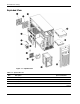
Illustrated Parts Catalog Exploded View Figure 1-1: Exploded view Table 1-1: Spare Parts List Item Description Spare Part Number 1 Power supply 372783-001 2 Rear system fan 372787-001 3 Rear system fan holder 374895-001 4 System board 373275-001 continued 1-2 HP ProLiant ML150 Generation 2 Server Maintenance and Service Guide
Illustrated Parts Catalog Table 1-1: Spare Parts List continued Item Description 5 Memory Spare Part Number a) 512-MB PC2700 DDR ECC Registered DIMM 370780-001 b) 1-GB PC2700 DDR ECC Registered DIMM 367167-001 c) 2-GB PC2700 DDR ECC Registered DIMM 367553-001 6 Heatsink 373584-001 7 3V Lithium battery for system board 234556-001 8 Processor a) Intel® Xeon™ 2.8-GHz/800-MHz 373580-001 b) Intel® Xeon™ 3.0-GHz/800-MHz 373581-001 c) Intel® Xeon™ 3.
Illustrated Parts Catalog Table 1-1: Spare Parts List continued Item Description Spare Part Number 24 SATA card 373013-001 25 SATA LED cable 377227-001 26 SATA hot-plug backplane 373012-001 27 SATA hot-plug hard drive cable a) Green cable 384450-001 b) Yellow cable 384451-001 c) White cable 384452-001 d) Blue cable 384453-001 28 80-GB SATA hot-plug hard drive, 7,200 rpm 29 HP ProLiant ML150 G2 Lights-Out 100 remote management card 372860-001 30 10/100/1000-T PCI card 3534
2 Removal and Replacement Procedures This chapter provides subassembly/module-level removal and replacement procedures for the HP ProLiant ML150 G2 Server. To service the server, a T-15 Torx screwdriver may be needed.
Removal and Replacement Procedures Electrostatic Discharge Information An electrostatic discharge (ESD) can damage static-sensitive devices or microcircuitry. Proper packaging and grounding techniques are necessary precautions to prevent damage. To prevent electrostatic damage, observe the following precautions: 2-2 • Transport products in static-safe containers such as conductive tubes, bags, or boxes. • Keep electrostatic-sensitive parts in their containers until they arrive at static-free stations.
Removal and Replacement Procedures Symbols on Equipment These symbols may be located on equipment in areas where hazardous conditions may exist. WARNING: This symbol, in conjunction with any of the following symbols, indicates the presence of a potential hazard. The potential for injury exists if warnings are not observed. Consult your documentation for specific details. This symbol indicates the presence of hazardous energy circuits or electric shock hazards. Refer all servicing to qualified personnel.
Removal and Replacement Procedures Preparation Procedures WARNING: Only authorized technicians trained by HP should attempt to repair this equipment. Because of the complexity of the individual boards and subassemblies, no one should attempt to make repairs at the component level or to make modifications to any printed wiring board. Improper repairs can create a safety hazard. CAUTION: Electrostatic discharge (ESD) can damage electronic components.
Removal and Replacement Procedures To power down the server: 1. Shut down the operating system in an orderly manner as directed in the operating system instructions. 2. If the server is on, press the power button to power down the server. If you are unable to shut down the server normally, press and hold the power button for more than four seconds to power down the server. 3. Be sure that the power indicator on the front panel is off and that the fan noise has stopped. 4.
Removal and Replacement Procedures Bezel Door To remove the bezel door: 1. Complete the preparation procedures. Refer to “Preparation Procedures” earlier in this chapter. 2. If the bezel lock is locked, unlock the bezel door using the included key.
Removal and Replacement Procedures 3. Open the bezel door fully to the right (1). 4. Lift the bezel door and then pull it away from the chassis (2). Figure 2-2: Removing the bezel door To replace the bezel door, reverse steps 3 through 4. NOTE: There is an EMI shield attached to the back of the bezel door for the SCSI non-hot-plug model. To remove the EMI shield, remove the four screws securing the shield to the bezel door.
Removal and Replacement Procedures Access Panel To remove the access panel: 1. Complete the preparation procedures. Refer to “Preparation Procedures” earlier in this chapter. 2. Loosen the two thumbscrews located on the right of the rear of the chassis (1). 3. Slide the access panel back about 1.5 cm (0.5 inch) (2). 4. Detach the top edge of the access panel from the chassis about 30 degrees, and then pull up to remove the access panel (3).
Removal and Replacement Procedures Cable Routing Diagrams Figure 2-4 through Figure 2-8 show the cable routing for the server. CAUTION: When routing cables, be sure that the cables are not in a position where they can be pinched or crimped.
Removal and Replacement Procedures Diskette Drive Signal Cable Figure 2-5: Diskette drive signal cable routing SCSI Hot-Plug Hard Drive Cable Figure 2-6: SCSI hot-plug hard drive cable routing 2-10 HP ProLiant ML150 Generation 2 Server Maintenance and Service Guide
Removal and Replacement Procedures SCSI Non-Hot-Plug Hard Drive Cable Figure 2-7: SCSI non-hot-plug hard drive cable routing SATA Hot-Plug Hard Drive Cable Figure 2-8: SATA hot-plug hard drive cable routing HP ProLiant ML150 Generation 2 Server Maintenance and Service Guide 2-11
Removal and Replacement Procedures NOTE: When connecting the SATA data cables, be sure to connect them in the following order: • The connectors on the SATA card from left to right: white, yellow, green, blue. • The connectors on the SATA backplane from top to bottom: white, yellow, green; blue on the bottom right corner. NOTE: There are two SATA LED cables which are tied together using a cable tie.
Removal and Replacement Procedures System Fan Modules To remove the rear system fan module: 1. Complete the preparation procedures. Refer to “Preparation Procedures” earlier in this chapter. 2. Open the bezel door. Refer to “Bezel Door” earlier in this chapter. 3. Remove the access panel. Refer to “Access Panel” earlier in this chapter. 4. Disconnect the rear system fan cable (1) from the system board. NOTE: Front system fan cable connection shown for clarity (2).
Removal and Replacement Procedures 5. Press the stopper in the center of the fan module on the rear of the chassis to release the fan module from the rear panel (1). 6. Pull down the fan module slightly to remove it from the rear panel (2). 7. Carefully lift the fan module out and away from the chassis (3). Figure 2-10: Removing the rear system fan module 8.
Removal and Replacement Procedures To remove the front system fan module: 1. Disconnect the front system fan cable from the system board. Refer to Figure 2-9. 2. Press the two tabs of the fan holder together towards the center of the fan module (1) to release the fan module from the front panel. 3. Carefully lift the fan module out and away from the chassis (2). Figure 2-12: Removing the front system fan module 4.
Removal and Replacement Procedures Drive Bay Configuration The server supports a maximum of nine drive bays (three are for removable media devices; six are for hot-plug hard drives). The removable media device bays contain a 3.5-inch 1.44-MB diskette drive; a 5.25-inch IDE optical device; and an empty drive bay. Figure 2-14: Server drive bay configuration Table 2-1: Drive Bay Configuration 2-16 Item Description 1 Optical drive 2 1.
Removal and Replacement Procedures Boot Priority The server’s boot order should be considered when selecting a boot device. This is especially important if you are installing a board that requires a higher priority in the boot order. The board’s boot priority is set by its slot location in the boot order. By default, the server searches for boot devices in the following order: 1. Legacy Floppy Drives (for the flexible diskette drive or virtual floppy) 2.
Removal and Replacement Procedures Flexible Diskette Drive To remove the flexible diskette drive: 1. Complete the preparation procedures. Refer to “Preparation Procedures” earlier in this chapter. 2. Open the bezel door. Refer to “Bezel Door” earlier in this chapter. 3. Press the two release tabs of the rails inward and slide the drive out far enough to expose the connectors. 4. Disconnect the power and signal cable connectors. 5. Hold the drive by its sides and gently slide the drive out of the drive bay.
Removal and Replacement Procedures 6. Remove the rails from the drive. Remove the two screws securing each rail on the side of the drive. Figure 2-16: Removing the rails from the flexible diskette drive To replace the flexible diskette drive, reverse steps 2 through 6. When attaching the rails to the sides of the flexible diskette drive, be sure that the screws are secured in the correct holes on the rails.
Removal and Replacement Procedures CD-ROM Drive To remove the CD-ROM drive: 1. Complete the preparation procedures. Refer to “Preparation Procedures” earlier in this chapter. 2. Open the bezel door. Refer to “Bezel Door” earlier in this chapter. 3. Press the two release tabs of the rails inward and slide the drive out far enough to expose the connectors. 4. Disconnect the power and signal cable connectors. 5. Hold the drive by its sides and gently slide the drive out of the drive bay.
Removal and Replacement Procedures 6. Remove the rails from the drive. Remove the two screws securing each rail on the side of the drive. Figure 2-19: Removing the rails from the CD-ROM drive To replace the CD-ROM drive, reverse steps 2 through 6. When attaching the rails to the sides of the CD-ROM drive, be sure that the screws are secured in the correct holes on the rails.
Removal and Replacement Procedures SCSI Hot-Plug Hard Drive Blank Carrier NOTE: The server does not need to be powered off to complete this operation. To remove the SCSI hot-plug hard drive blank carrier: 1. Open the bezel door. Refer to “Bezel Door” earlier in this chapter. 2. Locate the desired hard drive blank carrier. Hold the handle and slide the blank carrier out of the drive bay.
Removal and Replacement Procedures SCSI Hot-Plug Hard Drive NOTE: The server does not need to be powered off to complete this operation. To remove the SCSI hot-plug hard drive: 1. Open the bezel door. Refer to “Bezel Door” earlier in this chapter. 2. Push in the locking latch of the desired hard drive carrier (1) and then pull the ejector handle towards you (2). 3. Gently pull the hard drive carrier straight out to disengage the connection from the backplane and then out of the drive bay (3).
Removal and Replacement Procedures 5. Separate the hard drive and the carrier. a. Remove the two screws on each side of the carrier. b. Lift the hard drive out of the carrier. Figure 2-23: Separating the hard drive and carrier 6. Place the hard drive in an electrostatic protected container. Do not stack drives. To replace the SCSI hot-plug hard drive: 1. Assemble the hard drive and the carrier. a. Place the hard drive inside the carrier. b. Replace the two screws to each side of the carrier. 2.
Removal and Replacement Procedures SCSI Hot-Plug Hard Drive Cage To remove the SCSI hot-plug hard drive cage: 1. Complete the preparation procedures. Refer to “Preparation Procedures” earlier in this chapter. 2. Remove the bezel door. Refer to “Bezel Door” earlier in this chapter. 3. Remove the access panel. Refer to “Access Panel” earlier in this chapter. 4.
Removal and Replacement Procedures 9. Remove the screw on the side (1) and 10 screws on the front (2) securing the hard drive cage to the chassis with a T-15 Torx screwdriver. 10. Pull the hard drive cage out from the chassis (3). Figure 2-25: Removing the SCSI hot-plug hard drive cage To replace the SCSI hot-plug hard drive cage, reverse steps 2 through 10. When installing the hard drive cage in the chassis, be sure that the hard drive cage is seated properly on the supporter.
Removal and Replacement Procedures SCSI Non-Hot-Plug Hard Drive To remove the SCSI non-hot-plug hard drive: 1. Complete the preparation procedures. Refer to “Preparation Procedures” earlier in this chapter. 2. Open the bezel door. Refer to “Bezel Door” earlier in this chapter. 3. Remove the access panel. Refer to “Access Panel” earlier in this chapter. 4. Disconnect the SCSI hard drive cable and the 4-pin hard drive power connector from the hard drive to be removed.
Removal and Replacement Procedures 7. Remove the rails from the hard drive. Remove the two screws securing each rail on the side of the hard drive. Figure 2-27: Removing the rails from the non-hot-plug hard drive 8. Place the hard drive in an electrostatic protected container. Do not stack drives. To replace the SCSI non-hot-plug hard drive, reverse steps 2 through 8. When attaching the rails to the sides of the hard drive, be sure that the screws are secured in the correct holes on the rails.
Removal and Replacement Procedures SCSI Non-Hot-Plug Hard Drive Cage To remove the SCSI non-hot-plug hard drive cage: 1. Complete the preparation procedures. Refer to “Preparation Procedures” earlier in this chapter. 2. Remove the bezel door. Refer to “Bezel Door” earlier in this chapter. 3. Remove the access panel. Refer to “Access Panel” earlier in this chapter. 4. Remove all hard drives. Refer to “SCSI Non-Hot-Plug Hard Drive” earlier in this chapter. 5.
Removal and Replacement Procedures SATA Hot-Plug Hard Drive Blank Carrier NOTE: The server does not need to be powered off to complete this operation. To remove the SATA hot-plug hard drive blank carrier: 1. Open the bezel door. Refer to “Bezel Door” earlier in this chapter. 2. Push in the locking latch of the desired hard drive blank carrier (1). 3. With the locking latch still being pressed, hold the handle and slide the blank carrier out of the drive bay (2).
Removal and Replacement Procedures SATA Hot-Plug-Hard Drive NOTE: The server does not need to be powered off to complete this operation. To remove the SATA hot-plug hard drive: 1. Open the bezel door. Refer to “Bezel Door” earlier in this chapter. 2. Push in the locking latch of the desired hard drive carrier (1) and then pull the ejector handle towards you (2). 3. Gently pull the hard drive carrier straight out to disengage the connection from the backplane and then out of the drive bay (3).
Removal and Replacement Procedures 5. Separate the hard drive and the carrier. a. Remove the two screws on each side of the carrier. b. Lift the hard drive out of the carrier. Figure 2-32: Separating the hard drive and carrier 6. Place the hard drive in an electrostatic protected container. Do not stack drives. To replace a SATA hot-plug hard drive: 1. Assemble the hard drive and the carrier. a. Place the hard drive inside the carrier. b. Replace the two screws to each side of the carrier. 2.
Removal and Replacement Procedures SATA Hot-Plug Hard Drive Cage To remove the SATA hot-plug hard drive cage: 1. Complete the preparation procedures. Refer to “Preparation Procedures” earlier in this chapter. 2. Remove the bezel door. Refer to “Bezel Door” earlier in this chapter. 3. Remove the access panel. Refer to “Access Panel” earlier in this chapter. 4.
Removal and Replacement Procedures 9. Remove the screw on the side (1) and 10 screws on the front (2) securing the hard drive cage to the chassis with a T-15 Torx screwdriver. 10. Pull the hard drive cage out from the chassis (3). Figure 2-34: Removing the SATA hot-plug hard drive cage To replace the SATA hot-plug hard drive cage, reverse steps 2 through 10. When installing the hard drive cage in the chassis, be sure that the hard drive cage is seated properly on the supporter.
Removal and Replacement Procedures Expansion Slots Figure 2-35: Expansion slot locations Table 2-2: Expansion Slots Item Slot Slot Number 1 PCI-Express x4 6 2 32-bit 33-MHz PCI, 5-V 5 3 64-bit 66-MHz PCI-X, 3.3-V 4 4 64-bit 66-MHz PCI-X, 3.3-V 3 5 64-bit 66-MHz PCI-X, 3.3-V 2 6 64-bit 66-MHz PCI-X, 3.3-V 1 Pre-installed Do with a SCSI or SATA card not insert an add-on card with an RJ-45 connector into PCI-X slot 1.
Removal and Replacement Procedures Expansion Board NOTE: The procedures described below apply to all SCSI hot-plug, SCSI non-hot-plug, and SATA hotplug models. To remove an expansion board: 1. Complete the preparation procedures. Refer to “Preparation Procedures” earlier in this chapter. 2. Remove the access panel. Refer to “Access Panel” earlier in this chapter. 3. Disconnect any cables connected to the expansion board. 4. Remove the IO locking bracket. a. Lift the bracket up. b.
Removal and Replacement Procedures 5. Remove the expansion board. Figure 2-37: Removing an expansion board 6. Replace the IO locking bracket. To replace an expansion board, reverse steps 2 through 6.
Removal and Replacement Procedures Expansion Board Holder You may need to remove the expansion board holder when removing other components, such as the system board. To remove the expansion board holder: 1. Remove the expansion board(s) on the expansion board holder. Refer to “Expansion Board” earlier in this chapter. 2. Carefully place the server upside down. 3. Remove the two screws securing the expansion board holder to the chassis (1). 4. Remove the expansion board holder from the chassis (2).
Removal and Replacement Procedures Memory Module Guidelines CAUTION: To prevent damage to equipment or loss of information, make sure that the server is powered down, all cables are disconnected from the rear of the server, and the power cord is disconnected from the grounded (earthed) AC outlet before removing the access panel. CAUTION: To prevent damage to the system when handling components, refer to the HP ProLiant 100 Series Server User Guide available on the HP ProLiant ML150 G2 Server Support CD.
Removal and Replacement Procedures The following guidelines must be followed when memory modules are being added or replaced: 2-40 • DIMMs must be industry-standard 184-pin PC2700 333-MHz DDR registered ECC memory DIMMs. The DDR memory DIMMs must support CAS Latency 2, CL=2 or greater. They must also contain the mandatory Joint Electronic Device Engineering Council (JEDEC) Serial Presence Detect (SPD) information.
Removal and Replacement Procedures Memory Modules CAUTION: Electrostatic discharge (ESD) can damage electronic components. Be sure that you are properly grounded (earthed) before beginning any installation procedure. Refer to “Electrostatic Discharge Information” earlier in this chapter. To remove a memory module: 1. Complete the preparation procedures. Refer to “Preparation Procedures” earlier in this chapter. 2. Remove the access panel. Refer to “Access Panel” earlier in this chapter. 3.
Removal and Replacement Procedures Processors and Heatsinks Figure 2-41: Processor locations Table 2-4: Processor Locations Item Description 1 Processor 1 socket 2 Processor 1 fan connector 3 Processor 2 socket 4 Processor 2 fan connector CAUTION: Electrostatic discharge (ESD) can damage electronic components. Be sure that you are properly grounded (earthed) before beginning any installation procedure. Refer to “Electrostatic Discharge Information” earlier in this chapter.
Removal and Replacement Procedures To remove a processor and its heatsink: 1. Complete the preparation procedures. Refer to “Preparation Procedures” earlier in this chapter. 2. Remove the access panel. Refer to “Access Panel” earlier in this chapter. 3. Carefully lay the server on its unexposed side to gain access to the system board. 4. Locate the processor and heatsink assembly on the system board. 5. Disconnect the cooling fan connector from the system board. 6.
Removal and Replacement Procedures 8. Open the Zero Insertion Force (ZIF) lever to allow the removal of the processor (1). To open the ZIF lever, pull the lever out away from the ZIF socket and rotate it to the vertical position. 9. Grasp the processor by its edges, lift it out of the socket (2), and place it on a staticdissipating work surface or into an anti-static bag.
Removal and Replacement Procedures To replace the processor and its heatsink: 1. Open the ZIF lever (1). To open the ZIF lever, pull the lever out away from the ZIF socket and rotate it to the vertical position. CAUTION: Failure to fully open the ZIF lever will prevent the processor from seating properly during installation and can potentially lead to hardware damage. 2. Align the processor over the empty processor socket and insert the processor into the socket (2).
Removal and Replacement Procedures 4. Place a new thermal pad on the processor. 5. Align the heatsink to the holes around the processor socket. WARNING: Be sure that the processor heatsink sits squarely on the processor and is aligned with the fan facing towards the front of the server. Failure to install the heastink as directed may result in overheating or damage to the processor. 6. Tighten the four screws on the heatsink.
Removal and Replacement Procedures System Board To remove the system board: 1. Complete the preparation procedures. Refer to “Preparation Procedures” earlier in this chapter. 2. Remove the access panel. Refer to “Access Panel” earlier in this chapter. 3. Carefully lay the server on its unexposed side to gain access to the system board. 4. Remove the system fan modules. Refer to “System Fan Modules” earlier in this chapter. 5.
Removal and Replacement Procedures System Battery The server uses nonvolatile memory that requires a battery to retain system information when power is removed. The battery is on the system board. System Board Battery If the server no longer automatically displays the correct date and time, the system board battery that provides power to the real-time clock may need to be replaced. Under normal use, battery life is 5 to 10 years. WARNING: The system board contains a lithium battery.
Removal and Replacement Procedures 4. Press the battery release lever away from the battery (1). 5. Lift the battery up from that side and out of its holder (2). NOTE: If expansion boards are installed, you may need to remove them to gain access to the battery. Figure 2-47: Locating and removing a system board battery To replace the system board battery, reverse steps 2 through 5. IMPORTANT: The battery should be installed with the positive polarity (+ side) positioned up.
Removal and Replacement Procedures Power Supply To remove the power supply: 1. Complete the preparation procedures. Refer to “Preparation Procedures” earlier in this chapter. 2. Remove the access panel. Refer to “Access Panel” earlier in this chapter. 3. Remove the power cord from the power supply to be removed from the server. 4. Disconnect the power supply connections to the flexible diskette drive, CD-ROM drive, and backplane (for the hot-plug model) or hard drive (for the non-hot-plug model). 5.
Removal and Replacement Procedures Stands To remove the four stands from the chassis, one at a time: 1. Complete the preparation procedures. Refer to “Preparation Procedures” earlier in this chapter. 2. Carefully place the server upside down. 3. Remove the T-15 Torx screw that secures each stand to the chassis (1). 4. Slide each stand towards the proper direction to detach it from the chassis (2) and pull it off the base of the chassis (3).
3 Diagnostic Tools and Setup Utilities This chapter provides an overview of the Power-On Self-Test (POST), the POST error messages, and BIOS, SCSI and SATA setup utilities. POST POST is a series of diagnostic tests that checks firmware and assemblies to ensure that the server is properly functioning. POST runs automatically on HP servers when the server is powered up.
Diagnostic Tools and Setup Utilities Table 3-1: POST Error Messages continued Error Code Error Type Error Message 0271 Extend error Check date and time settings 0280 Extend error Previous boot incomplete - Default configuration used 0281 Extend error Memory size found by POST differed from EISA CMOS 02B0 Extend error Diskette drive A error 02B2 Extend error Incorrect drive A type - run SETUP 02D0 Extend error System cache error - Cache disabled 02D1 Extend error System memory exceeds
Diagnostic Tools and Setup Utilities BIOS Setup Utility The HP server BIOS Setup Utility is used to configure the following options: • Main • Advanced • Security • Power • Monitor • Boot • Exit Accessing the BIOS Setup Utility The BIOS Setup Utility menu offers the choices listed above, and the corresponding items are described in the topics below. 1. Power up the server and monitor. 2. Start the BIOS Setup Utility by pressing the F10 key on the HP logo screen.
Diagnostic Tools and Setup Utilities Menu Bar The BIOS Setup Utility provides a menu bar with several menu selections. The menu bar choices are described in the topics below. Main Menu Figure 3-1: Main menu of the BIOS Setup Utility Use this menu to set the server time and date, and configure the following items: 3-4 • Legacy Diskette A – Set the type of the flexible diskette drive. • IDE Channel 0 Master – Set the type of the CD-ROM drive and related settings.
Diagnostic Tools and Setup Utilities Advanced Menu Figure 3-2: Advanced menu of the BIOS Setup Utility WARNING: Incorrect settings may cause the server to malfunction. To correct the settings, press the F9 key to restore the default settings. Use this menu to configure the following items: • Installed O/S – Select the operating system that you use most often. • Reset Configuration Data – Set if you want to clear the Extended System Configuration Data (ESCD) data.
Diagnostic Tools and Setup Utilities Security Menu Figure 3-3: Security menu of the BIOS Setup Utility Use this menu to configure the following items: • Supervisor Password Is – Display if a Supervisor password is set. • User Password Is – Display if a User password is set. • Set Supervisor Password –Set the Supervisor password, which is required then to enter the BIOS Setup Utility.
Diagnostic Tools and Setup Utilities Power Menu Figure 3-4: Power menu of the BIOS Setup Utility Use this menu to configure the following items: • Power Savings – Select the power management mode for the server. • Wake On LAN – Enable or disable the Wake-On-LAN function. • Resume On Modem Ring – Enable or disable waking up the server when an incoming call is detected on the modem. • Resume On Time – Enable or disable waking up the server at a specific time.
Diagnostic Tools and Setup Utilities Monitor Menu Figure 3-5: Monitor menu of the BIOS Setup Utility This menu displays the data of the system monitoring. The items in this menu cannot be modified in the User mode. Consult the system supervisor if any changes are required. Boot Menu Figure 3-6: Boot menu of the BIOS Setup Utility Use this menu to configure the boot priority.
Diagnostic Tools and Setup Utilities Exit Menu Figure 3-7: Exit menu of the BIOS Setup Utility Use this menu to save changes or discard changes. When you exit, the server reboots. • Exit Saving Changes – Save the changes you have made and exit the BIOS Setup Utility. (You can also press the F10 key.) • Exit Discarding Changes – Exit the BIOS Setup Utility without saving the changes you have made. (You can also press the Esc key.) • Load Setup Defaults – Load the factory default values for all items.
Diagnostic Tools and Setup Utilities BIOS Update To update BIOS, you need to create the BIOS Update diskette. Creating the BIOS Update Diskette 1. Insert one blank, formatted 3.5-in diskette into the flexible diskette drive of a PC running Microsoft® Windows®. 2. Insert the HP ProLiant ML150 G2 Server Support CD in the CD-ROM drive of the above PC. 3. Click the desired operating system from the System Support Software list in the navigation bar. 4.
Diagnostic Tools and Setup Utilities SCSI Configuration Utility The HP server uses the SCSISelect Utility to verify or modify the SCSI controller settings for the devices connected to the system board. If you need to verify or modify SCSI controller settings, or if you need to low-level format SCSI disks or verify SCSI disk media, run the SCSISelect Utility. NOTE: You typically would not need to use this utility unless you are an experienced administrator or requested to do so by a support provider.
Diagnostic Tools and Setup Utilities 4. From the menu that displays, use the arrow keys to select the option you want, and press the Enter key. Figure 3-9: Options menu of the SCSISelect Utility NOTE: If you have difficulty viewing the display, press the F5 key to toggle between color and monochrome modes. (This feature may not work on some monitors.) Exiting SCSISelect 1.
Diagnostic Tools and Setup Utilities Configuring SCSISelect Settings SCSI Bus Interface Definitions • SCSI Controller ID (Default: 7) Set the SCSI ID for the SCSI host bus adapter. The Ultra320 SCSI Host Bus Adapter is set at 7, which gives it the highest priority on the SCSI bus. We recommend that you do not change this setting. • SCSI Controller Parity (Default: Enabled) Verify the accuracy of data transfer on the SCSI bus when set to Enabled.
Diagnostic Tools and Setup Utilities — Send Start Unit Command (Default: Yes) When set to Yes, the Start Unit Command is sent to the SCSI device at boot-up. The following three options have no effect when the SCSI host bus adapter BIOS is disabled. (The SCSI host bus adapter BIOS is normally enabled by default.) — BIOS Multiple LUN Support (Default: No) Leave this setting at No if the device does not have multiple Logical Unit Numbers (LUNs).
Diagnostic Tools and Setup Utilities The following options have no effect if Int 13 support is disabled. — Domain Validation (Default: Enabled) Determine the kinds of SCSI devices connected, reduce data transfer speed when legacy SCSI devices are detected, and display the resulting data transfer rate. — Support Removable Disks Under Int 13 as Fixed Disks (Default: Disabled) Determine which removable media drives are supported by the SCSI host bus adapter BIOS.
Diagnostic Tools and Setup Utilities Using the Taped Based One Button Disaster Recovery 1. Select Taped Based One Button Disaster Recovery (OBDR) from the menu that displays after starting SCSISelect. SCSISelect scans the SCSI bus (to determine the devices installed) and displays a list of all SCSI IDs and the devices assigned to each ID. 2. Use the arrow keys to move the cursor to the tape drive, and press the Enter key. 3. When prompted, press the Yes key to enable the OBDR support. 4.
Diagnostic Tools and Setup Utilities Figure 3-10: Options menu of the ARC Utility NOTE: If you have difficulty viewing the display, press the F5 key to toggle between color and monochrome modes. (This feature may not work on some monitors.) Exiting the ARC Utility 1. Press the Esc key until a message prompts you to exit (if you changed any settings, you are prompted to save the changes before you exit). 2. At the prompt, select Yes and press the Enter key to exit. Then press any key to reboot the server.
Diagnostic Tools and Setup Utilities Using ACU 1. Start the ARC Utility. Refer to “Starting the ARC Utility” earlier in this chapter. 2. From the ARC menu, select Array Configuration Utility. 3. From the ACU main menu, use the arrow keys to select the option you want, and press the Enter key.
Diagnostic Tools and Setup Utilities 5. Repeat Step 4 if you want to add another drive to be initialized. To deselect any disk, select the disk and press the Delete key. 6. Press the Enter key. 7. Read the warning message and make sure that you have selected the correct disk drives to initialize. Press the Y key to continue. Creating Arrays Before creating arrays, make sure the disks for the array are connected and installed in your system.
Diagnostic Tools and Setup Utilities Table 3-2: Creation Options continued RAID Level Create Using When Appropriate RAID 1 Build Creating a RAID 1 and you want to preserve data on an existing drive. You will be asked to select the source drive. The contents of the source drive are preserved and any data on the new drive is lost. RAID 1 Clear Creating a RAID 1 on new drives, or when you want to ensure that the new array contains no existing data. RAID 1 Quick Init Fastest way to create a RAID 1.
Diagnostic Tools and Setup Utilities 4. From the List of Arrays, select the array you want to make bootable, and press the Ctrl-B keys. This changes the selected array’s number to 00, making it the controller’s boot array. 5. Reboot the server. Deleting Arrays CAUTION: Back up the data on an array before you delete it. Otherwise, all data on the array is lost. Deleted arrays cannot be restored. 1. Start the ARC Utility. Refer to “Starting the ARC Utility” earlier in this chapter. 2.
Diagnostic Tools and Setup Utilities 4. You can use the following options: — Format Disk Allow you to simulate a low-level format of the hard drive by writing zeros to the entire disk. SATA drives are low-level formatted at the factory and do not need to be low-level formatted again. — Verify Disk Media Allow you to scan the media of a disk drive for defects.
4 Connectors, Jumpers, and LEDs This chapter contains illustrations and tables identifying and describing connectors, jumpers, and LED locations on the front panel, rear panel, system board and hard drives for the HP ProLiant ML150 G2 Server.
Connectors, Jumpers, and LEDs Connectors and Components This section contains illustrations and tables identifying connector locations and components on the server rear panel and system board. Rear Panel Components Figure 4-1 and Table 4-1 show and describe the locations of the components on the rear panel of the server.
Connectors, Jumpers, and LEDs System Board Components Figure 4-2 and Table 4-2 show and describe the locations of the components on the server system board.
Connectors, Jumpers, and LEDs Table 4-2: System Board Components continued 4-4 Item Description Item Description 21 PCI slot 4 (64-bit PCI-X) 31 DIMM slot 2 22 Winbond Super I/O chipset 32 DIMM slot 1 23 ATI Rage XL graphic chipset 33 USB 2.
Connectors, Jumpers, and LEDs Jumpers System Configuration Jumper Settings The server system board has a 3-position configuration jumper (J29). Figure 4-3 and Table 4-3 show the use of the jumper.
Connectors, Jumpers, and LEDs Clearing System Configuration Settings It may be necessary at some time to clear system configuration settings. When the system configuration jumper J29 is set to the Clear CMOS position, the system is prepared to erase all system configuration settings from both CMOS and nonvolatile RAM (NVRAM): IMPORTANT: Clearing NVRAM deletes the configuration information. 1. Complete the preparation procedures. Refer to “Preparation Procedures” in Chapter 2. 2. Remove the access panel.
Connectors, Jumpers, and LEDs LEDs Several status LEDs and buttons are located on the front and rear of the server. Problem diagnosis is aided by the LEDs that indicate the status of the components and operations of the server.
Connectors, Jumpers, and LEDs Figure 4-4: Power button and system status LEDs Table 4-4: Power Button and System Status LEDs Item Description Status Description 1 Drive activity indicator Off Inactive operation Flashing amber Disk drive activity Off System off (If the AC power cord is still connected, standby power is being supplied to the server.) Green System is on with AC power applied. N/A Allows the user to power up the server and power down the server.
Connectors, Jumpers, and LEDs Hot-Plug Hard Drive LEDs The SCSI and SATA hot-plug hard drive LEDs, located on each physical drive, are visible on the front of the server. • Status LED This LED indicates the drive operating condition: normal, warning, or failure. • Activity LED This LED indicates the disk drive access activity. This LED is controlled by the disk drive directly. When a drive is accessed, the LED shows a green light.
Connectors, Jumpers, and LEDs SATA LED Status Table 4-7 describes the LED signals used to indicate the operating status of a SATA disk drive.
Connectors, Jumpers, and LEDs Figure 4-5: Network Interface Controller (NIC) LEDs Table 4-8: Network Interface Controller (NIC) LEDs Item Description Status Condition 1 Green On Valid 100/1000 Mbps LAN link Flashing 100/1000 Mbps LAN activity On Valid 10/1000 Mbps LAN link Flashing 10/1000 Mbps LAN activity 2 Amber Note: The 1000 Mbps LAN link or activity is shown when both the green and amber LEDs are on or flashing.
5 Physical and Operating Specifications This chapter provides physical and operating specifications for the HP ProLiant ML150 G2 Server. The following specifications are provided: • System unit • Memory • 1.
Physical and Operating Specifications System Unit Table 5-1: System Unit Specifications Item Description Height (without feet) 42.8 cm (16.85 in) Height (with feet) 44.6 cm (17.56 in) Depth (without bezel) 54.1 cm (21.30 in) Depth (with bezel) 58.3 cm (22.95 in) Width (without feet) 20.5 cm (8.07 in) Width (with feet) 27.2 cm (10.71 in) Weight (no drives installed) 22.5 kg (49.
Physical and Operating Specifications Memory Table 5-2: Memory Specifications Item Description Size 512 MB, 1 GB and 2 GB Speed 333 MHz Type PC2700 ECC Registered DDR SDRAM DIMMs Note: DIMMs must be industry-standard 184-pin PC2700 DDR DIMMs. The DDR DIMMs must support CAS Latency 2 or greater. They must also contain the mandatory Joint Electronic Device Engineering Council (JEDEC) Serial Presence Detect (SPD). 1.44-MB Diskette Drive Table 5-3: 1.
Physical and Operating Specifications IDE CD-ROM Drive Table 5-4: IDE CD-ROM Drive Specifications Item Description Capacity 540 MB (mode 1, 12 cm) 650 MB (mode 2, 12 cm) Block size 2,048 bytes (mode 1); 2,340, 2,336 bytes (mode 2); 2,352 bytes (CD-DA); 2,328 (CD-XA) Dimensions Height 41.3 mm (1.63 in) Width 146 mm (5.75 in) Depth 184.7 mm (7.27 in) Weight <720 g (<25.4 oz) Data transfer rate Sustained 3,000 KBps (sustained 1X) Burst 16.67 MBps to 33.
Physical and Operating Specifications Wide Ultra3 SCSI Hard Drives Table 5-5: Wide Ultra3 SCSI Hard Drive Specifications Item 36-GB Drive 72-GB Drive 146-GB Drive Capacity 36 GB 72 GB 146 GB Height 1 in 1 in 1 in Width 4 in 4 in 4 in Interface Wide Ultra3 Wide Ultra3 Wide Ultra3 Transfer Rate 475~841 MBps 475~841 MBps 475~841 MBps Rotational Speed 15,000 RPM 10,000 RPM 10,000 RPM Bytes per sector 512 512 512 Operating Temperature 5°C to 55°C (41°F to 131°F) 5°C to 55°C (41
Physical and Operating Specifications LAN-on-Motherboard (LOM) Table 5-7: Integrated Broadcom 5721 Server LOM Specifications 5-6 Item Description Network interface 10Base-T/100Base-TX/1000Base-T Ethernet Compatibility IEEE 802.
Index A AC power, caution 4-8 access panel removing 2-8 replacing 2-8 ARC Utility 3-16 B battery handling, warning 2-48 part number 1-3 system board 2-48 system board, location 2-49 system board,replacing 2-48 bezel door part number 1-3 removing 2-6 replacing 2-7 BIOS Setup Utility 3-3 Advanced menu 3-5 Boot menu 3-8 Exit menu 3-9 Main menu 3-4 Monitor menu 3-8 Power menu 3-7 Security menu 3-6 BIOS update 3-10 boot configuring 3-8 boot order 2-17 C cable routing caution 2-9 diagrams 2-9 cautions AC power
Index removing 2-38 replacing 2-38 exploded view, parts 1-2 network activity 4-11 network link 4-11 network speed, illustrated 4-11 NIC, illustrated 4-11 NIC, summary 4-10 overview 4-7 power 4-8 system status 4-7 F Flexible diskette drive removing 2-18 replacing 2-19 front system fan part number 1-3 front system fan holder part number 1-3 front system fan module removing 2-15 M memory modules installation guidelines 2-40 part number 1-3 removing 2-41 replacing 2-41 size 5-3 socket locations, illustrated
Index SATA hot-plug hard drive cable – white 1-4 SATA hot-plug hard drive cable – yellow 1-4 SATA hot-plug hard drive cage 1-4 SATA LED cable 1-4 SCSI card 1-3 SCSI hot-plug back plane 1-3 SCSI hot-plug hard drive 1-3 SCSI hot-plug hard drive cable 1-3 SCSI hot-plug hard drive cage 1-3 SCSI hot-plug hard drive carrier 1-3 SCSI non-hot-plug hard drive 1-3 SCSI non-hot-plug hard drive cable 1-3 SCSI non-hot-plug hard drive cage 1-3 system board 1-2 parts catalog, illustrated 1-1 handling 2-2 illustrated 1-2
Index part number 1-3 removing 2-23 replacing 2-24 SCSI hot-plug hard drive blank carrier removing 2-22 replacing 2-22 SCSI hot-plug hard drive cable part number 1-3 SCSI hot-plug hard drive cage part number 1-3 removing 2-25 replacing 2-26 SCSI hot-plug hard drive carrier part number 1-3 SCSI LVD hard drive specifications 5-5 SCSI non-hot-plug hard drive cable routing 2-11 part number 1-3 removing 2-27 replacing 2-28 SCSI non-hot-plug hard drive cable part number 1-3 SCSI non-hot-plug hard drive cage part