
HP ProLiant ML150 Generation 5 Server Redundant Power Supply Installation Instructions

Redundant Power Supply
Installation Instructions
Legal notices
© Copyright 2008 Hewlett-Packard Development Company, L.P.
The information contained herein is subject to change without notice. The only
warranties for HP products and services are set forth in the express warranty
statements accompanying such products and services. Nothing herein should
be construed as constituting an additional warranty. HP shall not be liable for
technical or editorial errors or omissions contained herein.
Microsoft, Windows, and Windows NT are U.S. registered trademarks of
Microsoft Corporation. Windows Server 2003 is a trademark of Microsoft
Corporation. Intel, Pentium, and Itanium are trademarks or registered
trademarks of Intel Corporation or its subsidiaries in the United States and
other countries.
Overview
This document contains instructions for installing the optional
Redundant Power Supply (RPS) in HP servers.
For more information on preparing the server for installation, refer
to the documentation referenced on the Support CD bundled with
the server.
Kit contents
• RPS unit and power cables
• Mounting brackets and hardware
• This document
Important safety information
Read the installation instructions completely before beginning the
installation procedure. Refer to the document titled Important Safety
Information on the Support CD.
CAUTION: Electrostatic discharge (ESD) can damage
electronic components. Be sure you are properly
grounded (earthed) before beginning an installation
procedure.
Installation guidelines
This installation is to be performed by qualified personnel who are
knowledgeable of the procedures, precautions, and hazards
associated with equipment containing hazardous energy circuits.
HP ProLiant 100 Series servers come in two chassis designs for
access panel, right side and left side. Different bracket on the RPS
unit has to be removed to make the unit fitted to the different chassis
designs.
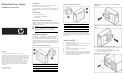
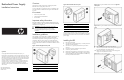
Figure 1 Chassis with right side access panel
Item Description
1 Power supply unit
2 System board
3 Air baffle
Figure 2 Chassis with left side access panel
Item Description
1 Power supply unit
2 System board
3 Air baffle
The connectors for the RPS unit may vary from system to system.
For proper cable connection, refer to the hood label or the system
board diagram to locate the correct connectors for the redundant
power supply.
Installing the RPS
1. Back up the server data.
2. Shut down the operating system (OS) in an orderly manner as
directed in the OS instructions.
3. If the server is on, press the power button to power down
the server.
4. Disconnect the power cord from the system chassis.
5. If necessary, unlock the chassis.
6. Release the rear thumbscrews and remove the access panel.
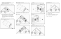
7. Remove the air baffle by pulling up slightly on the four tabs to
release the baffle from the chassis and lift the air baffle away
from the system board and chassis.
Figure 3 Removing the air baffle from the chassis with right side
access panel
Figure 4 Removing the air baffle from the chassis with left side access
panel
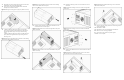
8. Place the server on its side with the open side up.
9. Disconnect all power cables of the existing power supply from
the system board and mass storage devices.
10. Remove the mounting screws that secure the existing power
supply to the rear panel of the chassis.
Figure 5 Removing the mounting screws
Part number 458632-002
May 2008 (Second Edition)