HP ProLiant ML150 G6 Server Installation Sheet Part Number 501527-004
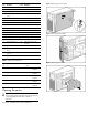
Identifying server components Figure 1 Front and rear panel components Item Description Item Description 1 Media bays 12 System Health LED 2 USB 2.0 ports (2) 13 AC input connector 3 Hard drive bays 1-4 14 Expansion slots 4 Hard drive bays 5-8 15 Keyboard connector 5 Optical drive bay 16 Mouse connector 6 Media eject button 17 Serial port connector 7 Front key lock 18 VGA connector 8 System power button/LED 19 USB 2.
Figure 3 Removing the access panel Item Description Item Description 5 CPU1_DIMM slot 4B 28 SATA 3 connector 6 CPU1_DIMM slot 5F 29 SATA 2 connector 7 CPU1_DIMM slot 6C 30 SATA 1 connector 8 Power supply connector (4-pin) 31 System fan 1 9 Expansion slot 5 32 System fan 2 (redundant) 10 Expansion slot 4 33 System fan 3 11 Expansion slot 3 34 System fan 4 12 Expansion slot 2 35 I2C connector (2) 13 Expansion slot 1 36 NMI button 14 CPU2_DIMM slot 6C 37 SGPIO 15 C
Installing an accessory card Figure 8 Installing a non-hot-plug drive Figure 6 Installing an accessory card Hot-plug drive installation Installing hard drives Figure 9 Installing a hot-plug-drive This system can support SATA and SAS drives in non-hot-plug and hot-plug hard disk drive cages. For detailed drive cabling information, see the server hood label.
Figure 11 Installing an optical drive Figure 12 Installing a DIMM Installing a processor Installing memory For a two-processor system, both processors must be of the same type. To access the processor sockets, remove the air baffle as shown previously. Memory installation guidelines are as follows: • Use registered and unbuffered DDR3 ECC DIMM. • Install DIMMs in identical pairs for best performance. • A single DIMM can be installed in DIMM slot 2A.
Figure 14 Reinserting the processor Figure 16 Removing the tool 5. 3. Align the processor installation tool with the socket, and then install the processor. THE PINS ON THE SYSTEM BOARD ARE VERY FRAGILE AND EASILY DAMAGED. Close the processor socket retaining bracket and the processor locking lever. The processor socket cover is automatically ejected. Remove the cover.
Figure 18 Installing the heatsink NOTE: Ensure that the air flow arrow on top of the heatsink is pointing towards the rear of the chassis.
Legal notices © Copyright 2009, 2012 Hewlett-Packard Development Company, L.P. The information contained herein is subject to change without notice. The only warranties for HP products and services are set forth in the express warranty statements accompanying such products and services. Nothing herein should be construed as constituting an additional warranty. HP shall not be liable for technical or editorial errors or omissions contained herein.