HP ProLiant ML310 Generation 2 Server Maintenance and Service Guide August 2005 (Third Edition) Part Number 378290-003
© Copyright 2005 Hewlett-Packard Development Company, L.P. The information contained herein is subject to change without notice. The only warranties for HP products and services are set forth in the express warranty statements accompanying such products and services. Nothing herein should be construed as constituting an additional warranty. HP shall not be liable for technical or editorial errors or omissions contained herein. Microsoft, Windows, and Windows NT are U.S.
Contents Illustrated parts catalog 5 Customer self repair ............................................................................................................................. 5 Mechanical components....................................................................................................................... 6 System components..............................................................................................................................
HP ProLiant ML310 Generation 2 Server Maintenance and Service Guide Server cabling 45 Hot-plug SCSI cabling ....................................................................................................................... 45 Hot-plug SATA cabling ..................................................................................................................... 46 Non-hot-plug SCSI cabling...........................................................................................................
Illustrated parts catalog In this section Customer self repair........................................................................................................................5 Mechanical components .................................................................................................................6 System components ........................................................................................................................
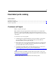
HP ProLiant ML310 Generation 2 Server Maintenance and Service Guide Mechanical components Item Description Assembly part number Spare part number Customer self repair 1 Bezel (w/o bezel key) 383678-001 382979-001 Yes 2 Access panel – – – 3 Air baffle 385712-001 385758-001 Yes Plastics kit – 382978-001 Yes 4 PCI retainer clips – – Yes 5 Release lever, full height drive bay – – Yes 6 Fan holder – – Yes 7 PCI expansion board guide – – Yes 8 Feet (4) – – Yes
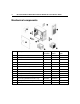
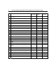
Illustrated parts catalog * not shown System components Item Description Assembly part number Spare part number Customer self repair 1 System fan module 381458-001 382109-001 Yes 2 Processor heatsink/cooling fan assembly 379265-001 382110-001 No 3 Processor a) Intel® Celeron® D 2.8-GHz/533-MHz FSB/256KB L2 cache 367744-001 382232-001 No b) Intel® Pentium® 4 3.0-GHz/800-MHz FSB/1-MB L2 cache* 390592-001 366643-001 No c) Intel® Pentium® 4 3.
HP ProLiant ML310 Generation 2 Server Maintenance and Service Guide Item Description Assembly part number Spare part number Customer self repair 398344-001 384787-001 No a) 256-MB PC-3200 unbuffered DDR DIMM 326315-441 382202-001 Yes b) 512-MB PC-3200 unbuffered DDR DIMM* 326316-441 351657-005 Yes c) 1-GB PC-3200 unbuffered DDR DIMM* 326317-451 351658-001 Yes d) Intel® Pentium® 4 3.
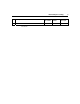
Illustrated parts catalog Item Description Assembly part number Spare part number Customer self repair 21 - 382204-001 Yes Return kit* * Not shown 9
Removal and replacement procedures In this section Required tools...............................................................................................................................11 Safety considerations....................................................................................................................12 Preparation procedures .................................................................................................................15 Bezel ............................
HP ProLiant ML310 Generation 2 Server Maintenance and Service Guide Safety considerations Before performing service procedures, review all the safety information. Preventing electrostatic discharge To prevent damaging the system, be aware of the precautions you need to follow when setting up the system or handling parts. A discharge of static electricity from a finger or other conductor may damage system boards or other staticsensitive devices.
Removal and replacement procedures • Do not disable the power cord grounding plug. The grounding plug is an important safety feature. • Plug the power cord into a grounded (earthed) electrical outlet that is easily accessible at all times. • Unplug the power cord from the power supply to disconnect power to the equipment. • Do not route the power cord where it can be walked on or pinched by items placed against it.
HP ProLiant ML310 Generation 2 Server Maintenance and Service Guide • At least two people are needed to safely unload the rack from the pallet. An empty 42U rack can weigh as much as 115 kg (253 lb), can stand more than 2.1 m (7 ft) tall, and may become unstable when being moved on its casters. • Never stand in front of the rack when it is rolling down the ramp from the pallet. Always handle the rack from both sides.
Removal and replacement procedures 15 CAUTION: Do not operate the server for long periods with the access panel open or removed. Operating the server in this manner results in improper airflow and improper cooling that can lead to thermal damage. Preparation procedures List of topics: Powering down the server ............................................................................................................15 Removing the server from the rack .....................................................
HP ProLiant ML310 Generation 2 Server Maintenance and Service Guide 2. Disconnect peripheral device and power cables. 3. Release the server from the tray. 4. Extend the server from the rack. 5. Remove the server from the tray and place it on a flat work surface. Unlocking the bezel Unlock and open the bezel before accessing the hard drive cage and before removing the access panel. Close and lock the bezel during normal server operations to ensure proper cooling airflow.
Removal and replacement procedures 17 Bezel To remove the component: To replace the component, reverse the removal procedure. Hot-plug SCSI hard drive CAUTION: To prevent improper cooling and thermal damage, do not operate the server unless all bays are populated with either a component or a blank. To remove the component: 1. Determine the status of the hard drive from the hot-plug hard drive LEDs ("Hot-plug SCSI hard drive LED combinations" on page 63, "Hot-plug SCSI hard drive LEDs" on page 62). 2.
HP ProLiant ML310 Generation 2 Server Maintenance and Service Guide 3. Remove the hard drive. To replace the component: 1. Slide the drive into the cage until it clicks, locking the drive into place. 2. Close the lever. IMPORTANT: When the drive is inserted, the drive LEDs flash for 2 seconds to indicate that the drive is seated properly and receiving power. 3.
Removal and replacement procedures 19 CAUTION: To prevent improper cooling and thermal damage, do not operate the server unless all bays are populated with either a component or a blank. To remove the component: 1. Determine the status of the hard drive from the hot-plug hard drive LEDs ("Hot-plug SCSI hard drive LED combinations" on page 63, "Hot-plug SCSI hard drive LEDs" on page 62).
HP ProLiant ML310 Generation 2 Server Maintenance and Service Guide 3. As the drive begins to spin, be sure that the drive LEDs illuminate one at a time and then turn off together to indicate that the system has recognized the new drive. In fault-tolerant configurations, allow the replacement drive to be reconstructed automatically with data from the other drives. While reconstruction is in progress, the online LED flashes. NOTE: The SATA RAID feature supports the use of two hard drives.
Removal and replacement procedures 21 To replace the component, reverse the removal procedure. PCI expansion board To remove the component: 1. Power down the server ("Powering down the server" on page 15). 2. Remove the bezel ("Bezel" on page 17). 3. Remove the access panel ("Access panel" on page 20). 4. Remove the expansion board from the slot. To replace the component, reverse the removal procedure.
HP ProLiant ML310 Generation 2 Server Maintenance and Service Guide • Do not attempt to recharge the battery. • Do not expose the battery to temperatures higher than 60°C (140°F). • Do not disassemble, crush, puncture, short external contacts, or dispose of in fire or water. • Replace only with the spare designated for this product. To remove the component: 1. Power down the server ("Powering down the server" on page 15). 2. Remove the bezel ("Bezel" on page 17). 3.
Removal and replacement procedures 23 DIMM You can expand server memory by installing PC-3200 DDR SDRAM DIMMs with Advanced ECC. The system supports up to four DIMMs for a maximum of 4 GB. Refer to "System Board Components (on page 57)" for DIMM slot locations and bank assignments. To remove the component: 1. Power down the server ("Powering down the server" on page 15). 2. Remove the bezel ("Bezel" on page 17). 3. Remove the access panel ("Access panel" on page 20). 4. Remove the DIMM.
HP ProLiant ML310 Generation 2 Server Maintenance and Service Guide DIMM installation guidelines Observe the following guidelines when installing additional memory: • DIMMs installed in the server must be Unbuffered DDR DRAM, 2.5 volts, 64 bits wide, and ECC. • If only a single DIMM is installed, it must be installed in slot 1A. • All DIMMs installed must be the same speed.
Removal and replacement procedures 25 Slot 1A Slot 2A Slot 3B Slot 4B Total memory Mode 1 GB 1 GB 1 GB 1 GB 4 GB Dual-channel interleaved Air baffle To remove the component: 1. Power down the server ("Powering down the server" on page 15). 2. Remove the bezel ("Bezel" on page 17). 3. Remove the access panel ("Access panel" on page 20). 4. Remove the air baffle. To replace the component, reverse the removal procedure. Fan To remove the component: 1.
HP ProLiant ML310 Generation 2 Server Maintenance and Service Guide 2. Remove the bezel ("Bezel" on page 17). 3. Remove the access panel ("Access panel" on page 20). 4. Remove the air baffle ("Air baffle" on page 25). 5. Remove the fan assembly. 6. Remove the fan from the holder. To replace the component, reverse the removal procedure.
Removal and replacement procedures Power supply To remove the component: 1. Power down the server ("Powering down the server" on page 15). 2. Remove the bezel ("Bezel" on page 17). 3. Remove the access panel ("Access panel" on page 20). 4. Remove the air baffle ("Air baffle" on page 25). 5. Disconnect the power and data cables. 6. Remove the power supply. To replace the component, reverse the removal procedure.
HP ProLiant ML310 Generation 2 Server Maintenance and Service Guide 2. Remove the bezel ("Bezel" on page 17). 3. Remove the access panel ("Access panel" on page 20). 4. Disconnect the fan cable from the system board. 5. Remove the heatsink fan assembly CAUTION: Heatsink retaining screws should be removed in diagonally opposite pairs (in an "X" pattern). CAUTION: The pins on the processor socket are very fragile. Any damage to them may require replacing the system board.
Removal and replacement procedures 6. Remove the processor. To replace the component: 1. Install the processor. CAUTION: To prevent possible server malfunction or damage to the equipment, be sure to align the processor pins with the corresponding holes in the socket. CAUTION: To prevent possible server malfunction or damage to the equipment, be sure to completely close the processor locking lever.
HP ProLiant ML310 Generation 2 Server Maintenance and Service Guide 2. Prepare the heatsink for installation: – If reusing the heatsink, clean the bottom of the heatsink with the provided alcohol pad, then apply a thin layer of thermal grease to the top of the processor. – If installing a new heatsink, remove the protective covering. 3. Install the heatsink fan assembly. CAUTION: Heatsink retaining screws should be tightened in diagonally opposite pairs (in an "X" pattern). 4.
Removal and replacement procedures 3. Remove the access panel ("Access panel" on page 20). 4. Disconnect the power and data cables. 5. Remove the diskette drive. To replace the component, reverse the removal procedure. CD-ROM/DVD-ROM drive CAUTION: To prevent improper cooling and thermal damage, do not operate the server unless all bays are populated with either a component or a blank. To remove the component: 1. Power down the server ("Powering down the server" on page 15). 2.
HP ProLiant ML310 Generation 2 Server Maintenance and Service Guide 5. Remove the CD-ROM or DVD-ROM drive. To replace the component, reverse the removal procedure. Installing a full-height tape drive option 1. Power down the server ("Powering down the server" on page 15). 2. Remove the bezel ("Bezel" on page 17, "Server warnings and cautions" on page 12). 3. Remove the access panel ("Access panel" on page 20). 4. Remove the media bay blanks ("Front panel components" on page 53).
Removal and replacement procedures 5. Use a screwdriver to disengage the two wire supports inside the full-height drive bays. 6. Install the tape drive.
HP ProLiant ML310 Generation 2 Server Maintenance and Service Guide 7. Install the retaining screw. IMPORTANT: HP recommends installing the tape drive on a separate SCSI cable to avoid a decrease in performance on other SCSI devices. 8. Connect the data and power cables to the back of the tape drive. 9. Connect the data cable into a SCSI controller channel ("System board components" on page 57). 10. Remove the applicable bezel blanks from the bezel ("Front panel components" on page 53). 11.
Removal and replacement procedures 2. Remove the bezel ("Bezel" on page 17). 3. Remove the access panel ("Access panel" on page 20). 4. Disconnect the power and data cables. 5. Remove the tape drive. To replace the component, reverse the removal procedure. Power button/LED board To remove the component: 1. Power down the server ("Powering down the server" on page 15). 2. Remove the bezel ("Bezel" on page 17). 3. Remove the access panel ("Access panel" on page 20). 4. Disconnect the power and data cables.
HP ProLiant ML310 Generation 2 Server Maintenance and Service Guide 5. Remove the front panel assembly. 6. Remove the power button/LED board. To replace the component, reverse the removal procedure.
Removal and replacement procedures 37 Hard drive (non-hot-plug) This procedure applies to non hot-plug drives only. If the server is equipped with hot-plug hard drives, refer to the hot-plug hard drive removal procedures ("Hotplug SATA/SAS hard drive" on page 18, "Hot-plug SCSI hard drive" on page 17). To remove the component: 1. Power down the server ("Powering down the server" on page 15). 2. Remove the bezel ("Bezel" on page 17). 3. Remove the access panel ("Access panel" on page 20). 4.
HP ProLiant ML310 Generation 2 Server Maintenance and Service Guide 6. Remove the hard drive. To replace the component, reverse the removal procedure. Hot-plug SCSI backplane To remove the component: 1. Power down the server ("Powering down the server" on page 15). 2. Remove the bezel ("Bezel" on page 17). 3. Remove the access panel ("Access panel" on page 20). 4. Remove all hot-plug hard drives ("Hot-plug SATA/SAS hard drive" on page 18, "Hot-plug SCSI hard drive" on page 17). 5.
Removal and replacement procedures 6. Remove the hard drive cage. 7. Remove the SCSI backplane.
HP ProLiant ML310 Generation 2 Server Maintenance and Service Guide NOTE: If replacing only the hard drive cage, retain the backplane for use with the replacement hard drive cage. To replace the component, reverse the removal procedure. Hot-plug SATA or SAS backplane To remove the component: 1. Power down the server ("Powering down the server" on page 15). 2. Remove the bezel ("Bezel" on page 17). 3. Remove the access panel ("Access panel" on page 20). 4.
Removal and replacement procedures 6. Remove the hard drive cage. 7. Remove the SATA or SAS backplane.
HP ProLiant ML310 Generation 2 Server Maintenance and Service Guide NOTE: If replacing only the hard drive cage, retain the backplane for use with the replacement hard drive cage. To replace the component, reverse the removal procedure. System board To remove the component: 1. Power down the server ("Powering down the server" on page 15). 2. Remove the bezel ("Bezel" on page 17). 3. Remove the access panel ("Access panel" on page 20). 4. Remove the air baffle ("Air baffle" on page 25). 5.
Removal and replacement procedures 6. Remove the system board. To replace the component, reverse the removal procedure. After you replace the system board, you must re-enter the server serial number and the product ID. 1. During the server startup sequence, press the F9 key to access RBSU. 2. Select the Advanced Options menu. 3. Select Serial Number. The following warning is displayed: Warning: The serial number should ONLY be modified by qualified service personnel.
HP ProLiant ML310 Generation 2 Server Maintenance and Service Guide 10. Press the F10 key to confirm exiting RBSU. The server will automatically reboot.
Server cabling In this section Hot-plug SCSI cabling..................................................................................................................45 Hot-plug SATA cabling................................................................................................................46 Non-hot-plug SCSI cabling ..........................................................................................................46 Non-hot-plug SATA cabling ..........................................
HP ProLiant ML310 Generation 2 Server Maintenance and Service Guide Hot-plug SATA cabling Item Cable description 1 Power cable 2 SATA cable Non-hot-plug SCSI cabling
Server cabling Item Cable description 1 SCSI cable 2 Power cable Non-hot-plug SATA cabling Item Cable description 1 SATA cable 2 Power cable 47
HP ProLiant ML310 Generation 2 Server Maintenance and Service Guide SAS cabling Item Cable description 1 Power cable 2 SAS cable
Diagnostic tools In this section Survey Utility ...............................................................................................................................49 Array Diagnostic Utility ...............................................................................................................49 HP Insight Diagnostics .................................................................................................................50 Integrated Management Log...........................
HP ProLiant ML310 Generation 2 Server Maintenance and Service Guide HP Insight Diagnostics HP Insight Diagnostics is a proactive server management tool, available in both offline and online versions, that provides diagnostics and troubleshooting capabilities to assist IT administrators who verify server installations, troubleshoot problems, and perform repair validation. HP Insight Diagnostics Offline Edition performs various in-depth system and component testing while the OS is not running.
Diagnostic tools 51 For more information, refer to the Management CD in the HP ProLiant Essentials Foundation Pack.
Server component identification In this section Front panel components................................................................................................................53 Front panel LEDs and buttons ......................................................................................................54 Rear panel components.................................................................................................................55 Rear panel LEDs and buttons ........................
HP ProLiant ML310 Generation 2 Server Maintenance and Service Guide Item Description 1 Media bays (bezel blanks) 2 Power On/Standby button 3 Hard drive bays 4 USB connectors (2) 5 Bezel lock 6 CD-ROM drive Front panel LEDs and buttons Item Description Status 1 CD-ROM drive ejector button N/A 2 Power On/Standby button N/A 3 Power on/Standby LED Amber = System has AC power and is in standby mode Green = System has AC power and is functioning Off = System has no AC power
Server component identification Item Description Status 4 Hard drive activity LED (for non-hot-plug) Green = Hard drives are properly connected and functioning NIC link/activity LED Green = Linked to network 5 Off = No hard drive activity Flashing green = Linked with activity on the network Off = No network connection 6 Internal system health LED Green = Normal (system on) Amber = System health is degraded Red = System health is critical Off = Normal (system off) 7 CD-ROM drive indicator LED
HP ProLiant ML310 Generation 2 Server Maintenance and Service Guide Item Description 4 Serial connector 5 Video connector 6 USB connectors (2) 7 RJ-45 Ethernet connector 8 Parallel connector Rear panel LEDs and buttons Item Description Status 1 10/100/1000 NIC link LED On = Link Off = No link 2 10/100/1000 NIC standby LED Flashing = Activity Off = No activity
Server component identification System board components Item Description Item Description 1 Mouse/keyboard connectors 10 Diskette drive connector 2 Processor power connector 11 RILOE connector 3 Power supply connector 12 32-bit PCI slot 4 DIMM slot 4 (B) 13 PCI Express x4 slot * 5 DIMM slot 3 (B) 14 PCI-X slot 2 6 DIMM slot 2 (A) 15 PCI-X slot 1 7 DIMM slot 1 (A) 16 RJ-45 connector 8 IDE connector 17 USB connectors (2) 9 SATA connector 18 Serial/video/parallel ports
HP ProLiant ML310 Generation 2 Server Maintenance and Service Guide Position Default Function S2 Off Off = System configuration can be changed On = System configuration is locked S3 Off Reserved S4 Off Reserved S5 Off Off = No function On = Clears power-on password and administrator password S6 Off Off = Normal On = ROM treats system configuration as invalid When the system maintenance switch position 6 is set to the On position, the system is prepared to erase all system configuratio
Server component identification System board LEDs Item LED description Status 1 PPM failure Off = Normal Amber = PPM failed or missing 2 Multibit error Off = Normal Amber = A multibit error has occurred 3 Single bit error Off = Normal Amber = Single bit error limit has been exceeded 4 DIMM 4 failure Off = Normal Amber = DIMM 4 has failed or is missing 5 DIMM 3 failure Off = Normal Amber = DIMM 3 has failed or is missing 6 DIMM 2 failure Off = Normal Amber = DIMM 2 has failed or is miss
HP ProLiant ML310 Generation 2 Server Maintenance and Service Guide Item LED description Status 8 Power good Off = Normal Green = Power failed 9 Processor failure Off = Normal Amber = Processor has failed 10 11 System temperature alert Off = Normal System fan failure Off = Normal Amber = System temperature has exceeded OS cautionary level Amber = System fan has failed or is missing 12 Processor fan failure Off = Normal Amber = Processor fan has failed or is missing System LEDs and in
Server component identification System LED and color Internal health LED color Status PPM failure, slot X (Amber) Red • PPM in slot X has failed. • PPM is not installed in slot X, but the corresponding processor is installed. DIMM failure, slot X (Amber) Red • DIMM in slot X has failed. • DIMM has experienced a multi-bit error. • DIMM in slot X has reached single-bit correctable error threshold. • DIMM in slot X is in a pre-failure condition.
HP ProLiant ML310 Generation 2 Server Maintenance and Service Guide SCSI IDs Hot-plug SCSI hard drive LEDs
Server component identification Item LED description Status 1 Activity status On = Drive activity 63 Flashing = High activity on the drive or drive is being configured as part of an array. Off = No drive activity 2 Online status On = Drive is part of an array and is currently working. Flashing = Drive is actively online. Off = Drive is offline.
HP ProLiant ML310 Generation 2 Server Maintenance and Service Guide Activity LED (1) Online LED (2) Fault LED Interpretation (3) Flashing Flashing Flashing Do not remove the drive. Removing a drive may cause data loss in non-fault-tolerant configurations. Either (1) the drive is part of an array being selected by an array configuration utility; (2) Drive Identification has been selected in HP SIM; or (3) drive firmware is being updated.
Server component identification SATA or SAS hard drive LEDs Item LED description Status 1 Fault/UID status Amber = Drive failure Flashing amber = Fault-process activity Blue = Unit identification is active Off = No fault-process activity 2 Online/Activity status Green = Drive activity Flashing green = High activity on the drive or drive is being configured as part of an array Off = No drive activity IMPORTANT: When hot-plug SATA hard drives are installed, SATA LED functionality and full SATA hot-
HP ProLiant ML310 Generation 2 Server Maintenance and Service Guide Fan locations Item Description 1 System fan 2 Processor fan
Specifications In this section Server specifications.....................................................................................................................67 Environmental specifications .......................................................................................................68 Hot-plug power supply calculations .............................................................................................68 1.44-MB diskette drive specifications ................................
HP ProLiant ML310 Generation 2 Server Maintenance and Service Guide *10 A is required for 100 to 127 VAC; 5 A is required for 200 to 240 VAC. Environmental specifications Specification Value Temperature range* Operating 10°C to 35°C (50°F to 95°F) Shipping -10°C to 60°C (14°F to 140°F) Maximum wet bulb temperature 28°C (82.4°F) Relative humidity (noncondensing)** Operating 20% to 80% Non-operating 20% to 90% * All temperature ratings shown are for sea level.
Specifications Specification Value Depth 130 mm (5.1 in) LEDs (front panel) Green = On Read/write capacity per diskette High density 1.
HP ProLiant ML310 Generation 2 Server Maintenance and Service Guide Specification Value Capacity 550 MB (mode 1, 12 cm) 640 MB (mode 2, 12 cm) Block size 2368, 2352 bytes (mode 0) 2352, 2340, 2336, 2048 bytes (mode 1) 2352, 2340, 2336, 2048 bytes (mode 2) Dimensions Height 12.7 mm (0.50 in) Depth 132.08 mm (5.20 in) Width 132.08 mm (5.20 in) Weight 0.34 kg (0.75 lb) Data transfer rate Sustained 150 KB/s (sustained 1X), 1500/3600 KB/s (10X to 24X) Burst 16.
Specifications Specification Value Operating conditions Temperature 5°C to 45°C (41°F to 118°F) Humidity 5% to 90% 71
Acronyms and abbreviations ABEND abnormal end ACU Array Configuration Utility ASR Automatic Server Recovery DDR double data rate DIMM dual inline memory module ECC error checking and correcting HBA host bus adapter IEC International Electrotechnical Commission
HP ProLiant ML310 Generation 2 Server Maintenance and Service Guide iLO Integrated Lights-Out IML Integrated Management Log IPL initial program load IRQ interrupt request LDAP Lightweight Directory Access Protocol MPS multi-processor specification NEMA National Electrical Manufacturers Association NFPA National Fire Protection Association NIC network interface controller NMI non-maskable interrupt
Acronyms and abbreviations NVRAM non-volatile memory PCI-X peripheral component interconnect extended PDU power distribution unit POST Power-On Self Test PPM Processor Power Module PSP ProLiant Support Pack PXE preboot eXecution environment RAID redundant array of inexpensive (or independent) disks RBSU ROM-Based Setup Utility RILOE II Remote Insight Lights-Out Edition II 75
HP ProLiant ML310 Generation 2 Server Maintenance and Service Guide SAS serial attached SCSI SATA serial ATA SCSI small computer system interface SDRAM synchronous dynamic RAM SIM Systems Insight Manager TMRA recommended ambient operating temperature UID unit identification VHDCI very high density cable interconnect WOL Wake-on LAN
Index expansion slots 55 F A AC power supply 27, 56 access panel 20 ADU (Array Diagnostic Utility) 49 air baffle 25 ASR (Automatic Server Recovery) 73 Automatic Server Recovery (ASR) 73 B battery 21 bezel, removing 17 buttons 53 C fan assembly 25 fan LED 62 fan zones 63 fans 25, 66 fans, replacing 25 front panel components 53 front panel LEDs 54 H hard drive LEDs 62, 63 hard drive, replacing 17, 18, 37 hard drives 62, 63 hard drives, determining status of 62, 63 hard drives, removing 17, 18, 37 he
HP ProLiant ML310 Generation 2 Server Maintenance and Service Guide overtemperature LED 60, 63 specifications 67, 68 specifications, environmental 68 specifications, server 67 static electricity 12 Survey Utility 49 switches 57 system board 42, 57, 59 system board battery 21 system board LEDs 59 P T parallel connector 55 power button/LED board 35 power cord connector 55 power supplies 27, 55, 56 power supply LEDs 56, 60 powering down 15 PPM failure LEDs 60, 63 preparation procedures 15 processor fa