HP ProLiant ML310 Generation 4 Server Maintenance and Service Guide Part Number 419352-003 October 2007 (Third Edition)
© Copyright 2006, 2007 Hewlett-Packard Development Company, L.P. The information contained herein is subject to change without notice. The only warranties for HP products and services are set forth in the express warranty statements accompanying such products and services. Nothing herein should be construed as constituting an additional warranty. HP shall not be liable for technical or editorial errors or omissions contained herein. Microsoft and Windows are U.S.
Contents Customer self repair ...................................................................................................................... 5 Parts only warranty service ......................................................................................................................... 5 Illustrated parts catalog ............................................................................................................... 16 Mechanical components.............................................
ROMPaq disaster recovery ....................................................................................................................... 56 Automatic ROMPaq disaster recovery .............................................................................................. 56 Manual ROMPaq disaster recovery.................................................................................................. 57 Server component identification..................................................................
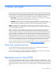
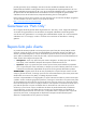
Customer self repair HP products are designed with many Customer Self Repair (CSR) parts to minimize repair time and allow for greater flexibility in performing defective parts replacement. If during the diagnosis period HP (or HP service providers or service partners) identifies that the repair can be accomplished by the use of a CSR part, HP will ship that part directly to you for replacement. There are two categories of CSR parts: • Mandatory—Parts for which customer self repair is mandatory.
• Obligatoire - Pièces pour lesquelles la réparation par le client est obligatoire. Si vous demandez à HP de remplacer ces pièces, les coûts de déplacement et main d'œuvre du service vous seront facturés. • Facultatif - Pièces pour lesquelles la réparation par le client est facultative. Ces pièces sont également conçues pour permettre au client d'effectuer lui-même la réparation.
NOTA: alcuni componenti HP non sono progettati per la riparazione da parte del cliente. Per rispettare la garanzia, HP richiede che queste parti siano sostituite da un centro di assistenza autorizzato. Tali parti sono identificate da un "No" nel Catalogo illustrato dei componenti. In base alla disponibilità e alla località geografica, le parti CSR vengono spedite con consegna entro il giorno lavorativo seguente.
anrufen und sich von einem Mitarbeiter per Telefon helfen lassen. Den Materialien, die mit einem CSRErsatzteil geliefert werden, können Sie entnehmen, ob das defekte Teil an HP zurückgeschickt werden muss. Wenn es erforderlich ist, das defekte Teil an HP zurückzuschicken, müssen Sie dies innerhalb eines vorgegebenen Zeitraums tun, in der Regel innerhalb von fünf (5) Geschäftstagen.
Centro de asistencia técnica de HP y recibirá ayuda telefónica por parte de un técnico. Con el envío de materiales para la sustitución de componentes CSR, HP especificará si los componentes defectuosos deberán devolverse a HP. En aquellos casos en los que sea necesario devolver algún componente a HP, deberá hacerlo en el periodo de tiempo especificado, normalmente cinco días laborables. Los componentes defectuosos deberán devolverse con toda la documentación relacionada y con el embalaje de envío.
periode, gewoonlijk vijf (5) werkdagen, retourneren aan HP. Het defecte onderdeel moet met de bijbehorende documentatie worden geretourneerd in het meegeleverde verpakkingsmateriaal. Als u het defecte onderdeel niet terugzendt, kan HP u voor het vervangende onderdeel kosten in rekening brengen. Bij reparatie door de klant betaalt HP alle verzendkosten voor het vervangende en geretourneerde onderdeel en kiest HP zelf welke koerier/transportonderneming hiervoor wordt gebruikt.
Para obter mais informações sobre o programa de reparo feito pelo cliente da HP, entre em contato com o fornecedor de serviços local. Para o programa norte-americano, visite o site da HP (http://www.hp.com/go/selfrepair). Serviço de garantia apenas para peças A garantia limitada da HP pode incluir um serviço de garantia apenas para peças. Segundo os termos do serviço de garantia apenas para peças, a HP fornece as peças de reposição sem cobrar nenhuma taxa.
Customer self repair 12
Customer self repair 13
Customer self repair 14
Customer self repair 15
Illustrated parts catalog Mechanical components Item Description Spare part number Customer self repair (on page 5) 1 Bezel 382979-001 Mandatory1 2 Access panel 435921-001 Mandatory1 3 Plastics kit 435923-001 Mandatory1 Illustrated parts catalog 16
Item Description Spare part number Customer self repair (on page 5) a) PCI retainer clips — — b) Release lever, full-height drive bay — — c) Fan holder — — d) PCI expansion board guide — — 4 Hot-plug SATA/SAS hard drive cage 404178-001 Mandatory1 5 SAS hard drive blank 389015-001 Mandatory1 6 System fan air baffle 432465-001 Mandatory1 Mandatory—Parts for which customer self repair is mandatory.
HP realice su sustitución, puede o no conllevar costes adicionales, dependiendo del tipo de servicio de garantía correspondiente al producto. 3 No: No—Algunos componentes no están diseñados para que puedan ser reparados por el usuario. Para que el usuario haga valer su garantía, HP pone como condición que un proveedor de servicios autorizado realice la sustitución de estos componentes. Dichos componentes se identifican con la palabra “No” en el catálogo ilustrado de componentes.
System components Item Description Spare part number Customer self repair (on page 5) System components 7 Hard drive cage fan baffle 435926-001 Mandatory1 8 Hard drive cage fan 435925-001 Mandatory1 9 System fan module 398406-001 Mandatory1 10 Processor heatsink 434596-001 Optional2 11 Processor — — a) 2.8-GHz Intel® Pentium® D 820, 800-MHz FSB, 2-MB L2 cache* 392419-005 Optional2 b) 3.4-GHz Intel® Pentium® D 945, 800-MHz FSB, 4-MB L2 cache* 435485-001 Optional2 c) 3.
Item Description Spare part number Customer self repair (on page 5) d) 2.13-GHz Intel® Xeon® 3050, 1066-MHz FSB, 2- 436523-001 MB L2 cache* Optional2 e) 2.4-GHz Intel® Xeon® 3060, 1066-MHz FSB, 4MB L2 cache* 432943-001 Optional2 f) 1.
Item Description Spare part number Customer self repair (on page 5) 25 403043-001 Mandatory1 405168-001 Mandatory1 Front USB connector cable assembly* Miscellaneous 26 Bezel key* * Not shown 1 Mandatory—Parts for which customer self repair is mandatory. If you request HP to replace these parts, you will be charged for the travel and labor costs of this service. 2 Optional—Parts for which customer self repair is optional. These parts are also designed for customer self repair.
sustitución de estos componentes. Dichos componentes se identifican con la palabra “No” en el catálogo ilustrado de componentes. Mandatory: Verplicht—Onderdelen waarvoor Customer Self Repair verplicht is. Als u HP verzoekt deze onderdelen te vervangen, komen de reiskosten en het arbeidsloon voor uw rekening. 2 Optional: Optioneel—Onderdelen waarvoor reparatie door de klant optioneel is. Ook deze onderdelen zijn ontworpen voor reparatie door de klant.
Removal and replacement procedures Required tools You need the following items for some procedures: • T-15 Torx screwdriver • HP Insight Diagnostics software ("HP Insight Diagnostics" on page 56) Safety considerations Before performing service procedures, review all the safety information. Preventing electrostatic discharge To prevent damaging the system, be aware of the precautions you need to follow when setting up the system or handling parts.
WARNING: To reduce the risk of personal injury from hot surfaces, allow the drives and the internal system components to cool before touching them. WARNING: To reduce the risk of personal injury, electric shock, or damage to the equipment, remove the power cord to remove power from the server. The front panel Power On/Standby button does not completely shut off system power. Portions of the power supply and some internal circuitry remain active until AC power is removed.
WARNING: This server is very heavy. To reduce the risk of personal injury or damage to the equipment: • Observe local occupational health and safety requirements and guidelines for manual material handling. • Get help to lift and stabilize the product during installation or removal, especially when the product is not fastened to the rails. When the server weighs more than 22.5 kg (50 lb), at least two people must lift the server into the rack together.
Unlock the tower bezel The removable bezel must be unlocked and opened before accessing the hard drive cage and media bays. It must be unlocked before removing the access panel. The bezel must remain closed during normal server operations. If necessary, remove the bezel by lifting the open bezel from the chassis. Access panel WARNING: To reduce the risk of personal injury from hot surfaces, allow the drives and the internal system components to cool before touching them.
3. Unlock and open the bezel ("Unlock the tower bezel" on page 26). 4. Remove the access panel ("Access panel" on page 26). 5. Remove the system fan air baffle. To replace the component, reverse the removal procedure. System fan module and fan holder To remove the component: 1. Power down the server (on page 25). 2. Remove the server from the rack, if necessary ("Remove the server from the rack" on page 25). 3. Remove the bezel ("Unlock the tower bezel" on page 26). 4.
6. Remove the system fan module. 7. Remove the system fan module from the fan holder. To replace the component, reverse the removal procedure. Hard drive cage fan and baffle To remove the component: 1. Power down the server (on page 25). 2. Remove the server from the rack, if necessary ("Remove the server from the rack" on page 25). 3. Remove the bezel ("Unlock the tower bezel" on page 26). 4. Remove the access panel ("Access panel" on page 26). 5.
6. Remove the hard drive fan cage and baffle. 7. Remove the hard drive cage fan. To replace the component, reverse the removal procedure. Hot-plug SAS and SATA hard drives Hot-plug SATA and hot-plug SAS hard drives can be used interchangeably when a SAS controller is installed. The embedded SATA controller supports only SATA drives. CAUTION: To prevent improper cooling and thermal damage, do not operate the server unless all bays are populated with either a component or a blank.
IMPORTANT: When hot-plug SATA hard drives are installed, SATA LED functionality and full SATA hot-plug capability are not supported with the embedded controller. For full LED and hotplug support, an optional SATA RAID or SAS controller must be installed. 2. Unlock and open the bezel ("Unlock the tower bezel" on page 26). 3. Remove the hard drive. To replace the component: 1. Slide the drive into the cage until it clicks, locking the drive into place. 2. Close the lever.
7. Disconnect the power and data cables. 8. Remove the hot-plug hard drive cage. NOTE: If replacing only the hard drive cage, retain the backplane for use with the replacement hard drive cage. To replace the component, reverse the removal procedure. Hot-plug SAS or SATA backplane To remove the component: 1. Power down the server (on page 25). 2. Remove the server from the rack, if necessary ("Remove the server from the rack" on page 25). 3. Remove the bezel ("Unlock the tower bezel" on page 26).
9. Remove the SAS or SATA backplane. To replace the component, reverse the removal procedure. Diskette drive CAUTION: To prevent improper cooling and thermal damage, do not operate the server unless all bays are populated with either a component or a blank. To remove the component: 1. Power down the server (on page 25). 2. Remove the server from the rack, if necessary ("Remove the server from the rack" on page 25). 3. Remove the bezel ("Unlock the tower bezel" on page 26). 4.
6. Remove the diskette drive. To replace the component, reverse the removal procedure. CD-ROM/DVD-ROM drive CAUTION: To prevent improper cooling and thermal damage, do not operate the server unless all bays are populated with either a component or a blank. To remove the component: 1. Power down the server (on page 25). 2. Remove the server from the rack, if necessary ("Remove the server from the rack" on page 25). 3. Remove the bezel ("Unlock the tower bezel" on page 26). 4.
To replace the component, reverse the removal procedure. Hot-plug power supply CAUTION: Leave all failed power supplies installed until ready to replace with a working power supply. 1. Disconnect the power cord of the failed power supply from the AC power source. 2. Disconnect the power cord from the failed power supply. 3. Remove the power supply. To replace the component, reverse the removal procedure. Redundant power supply backplane assembly To remove the component: 1.
9. Remove the redundant power supply backplane assembly. To replace the component, reverse the removal procedure. Non-redundant power supply To remove the component: 1. Power down the server (on page 25). 2. Remove the server from the rack, if necessary ("Remove the server from the rack" on page 25). 3. Remove the bezel ("Unlock the tower bezel" on page 26). 4. Remove the access panel ("Access panel" on page 26). 5. Remove the system fan air baffle ("System fan air baffle" on page 26). 6.
8. Remove the power supply. To replace the component, reverse the removal procedure. DIMM To remove the component: 1. Power down the server (on page 25). 2. Remove the server from the rack, if necessary ("Remove the server from the rack" on page 25). 3. Remove the bezel ("Unlock the tower bezel" on page 26). 4. Remove the access panel ("Access panel" on page 26). 5. Remove the system fan air baffle ("System fan air baffle" on page 26). 6. Remove the DIMM.
You can expand server memory by installing PC2-5300 DDR2 SDRAM DIMMs with ECC. The system supports up to four DIMMs for a maximum of 8 GB. IMPORTANT: DIMMs do not seat fully if turned the wrong way. For DIMM slot locations and bank assignment, see "System board components ("System board components" on page 62)." Observe the following guidelines when installing additional memory: • DIMMs installed in the server must be unbuffered PC2-5300 DDR2 DRAM, 64 bits wide, and ECC.
4. Remove the access panel ("Access panel" on page 26). 5. Remove the system fan air baffle ("System fan air baffle" on page 26). 6. Remove the heatsink. CAUTION: Heatsink retaining screws should be loosened in diagonally opposite pairs (in an "X" pattern). To replace the heatsink: 1. Use the alcohol swab to remove all the existing thermal grease from the processor. Allow the alcohol to evaporate before continuing. 2.
3. Install the heatsink. CAUTION: Heatsink retaining screws should be tightened in diagonally opposite pairs (in an "X" pattern). 4. Install the system fan air baffle. 5. Install the access panel. 6. Install the bezel ("Unlock the tower bezel" on page 26). Processor CAUTION: Removal of the processor or heatsink renders the thermal layer between the processor and heatsink useless. Clean the component with the provided alcohol swab, then add thermal grease.
7. Open the processor retaining latch and the processor socket retaining bracket. 8. Using your fingers, remove the failed processor. To replace the component: IMPORTANT: Be sure the processor remains inside the processor installation tool.
1. If the processor has separated from the installation tool, carefully re-insert the processor in the tool. 2. Align the processor installation tool with the socket and install the spare processor. CAUTION: The processor is designed to fit one way into the socket. Use the alignment guides on the processor and socket to properly align the processor with the socket. Refer to the server hood label for specific instructions.
3. Press down firmly until the processor installation tool clicks and separates from the processor, and then remove the processor installation tool. 4. Close the processor retaining latch and the processor socket retaining bracket. 5. Clean the old thermal grease from the heatsink with the alcohol swab. Allow the alcohol to evaporate before continuing.
6. Apply all the grease to the top of the processor in one of the following patterns to ensure even distribution: 7. Install the heatsink. CAUTION: Heatsink retaining screws should be tightened in diagonally opposite pairs (in an "X" pattern). 8. Install the system fan air baffle. 9. Install the access panel. 10. Install the bezel. 11. Power up the server.
1. Power down the server (on page 25). 2. Remove the server from the rack, if necessary ("Remove the server from the rack" on page 25). 3. Remove the bezel ("Unlock the tower bezel" on page 26). 4. Remove the access panel ("Access panel" on page 26). 5. Remove the expansion board. To replace the component, reverse the removal procedure. Power button/LED board To remove the component: 1. Power down the server (on page 25). 2.
6. Remove the front panel assembly. 7. Remove the power button/LED board. To replace the component, reverse the removal procedure. Battery If the server no longer automatically displays the correct date and time, you may need to replace the battery that provides power to the real-time clock. Under normal use, battery life is 5 to 10 years.
WARNING: The computer contains an internal lithium manganese dioxide, a vanadium pentoxide, or an alkaline battery pack. A risk of fire and burns exists if the battery pack is not properly handled. To reduce the risk of personal injury: • Do not attempt to recharge the battery. • Do not expose the battery to temperatures higher than 60°C (140°F). • Do not disassemble, crush, puncture, short external contacts, or dispose of in fire or water. • Replace only with the spare designated for this product.
4. Remove the access panel ("Access panel" on page 26). 5. Remove the system fan air baffle ("System fan air baffle" on page 26). 6. Remove the system fan module ("System fan module and fan holder" on page 27). 7. Remove all DIMMs ("DIMM" on page 36). 8. Remove all PCI expansion boards ("Expansion boards" on page 43). 9. Remove the hard drive cage fan and baffle ("Hard drive cage fan and baffle" on page 28). 10. Disconnect all system board cabling. 11. Remove the heatsink.
CAUTION: To avoid damage to the processor: • Handle the processor only by the edges. • Do not touch the bottom of the processor, especially the contact area. 13. Using your fingers, remove the processor from the failed system board. CAUTION: To avoid damage to the system board: • Do not touch the processor socket contacts. • Always install the processor socket cover after removing the processor from the socket. • Do not tilt or slide the processor when lowering the processor into the socket. 14.
a. Open the processor retaining latch and the processor socket retaining bracket. b. Remove the processor socket protective cover. 3. Install the processor socket cover onto the processor socket of the failed system board. 4. Install the processor on the spare system board. CAUTION: The processor is designed to fit one way into the socket. Use the alignment guides on the processor and socket to properly align the processor with the socket. Refer to the server hood label for specific instructions.
5. Close the processor retaining latch and the processor socket retaining bracket. 6. Clean the old thermal grease from the heatsink and the top of the processor with the alcohol swab. Allow the alcohol to evaporate before continuing.
7. Apply all the grease to the top of the processor in one of the following patterns to ensure even distribution: 8. Install the heatsink. CAUTION: Heatsink retaining screws should be tightened in diagonally opposite pairs (in an "X" pattern). 9. Install all components removed from the failed system board. IMPORTANT: Install all components with the same configuration that was used on the failed system board. 10. Install the access panel. 11. Install the bezel. 12.
After you replace the system board, you must re-enter the server serial number and the product ID. 1. During the server startup sequence, press the F9 key to access RBSU. 2. Select the Advanced Options menu. 3. Select Serial Number. The following warning is displayed: Warning: The serial number should ONLY be modified by qualified service personnel. This value should always match the serial number located on the chassis. 4. Press the Enter key to clear the warning. 5. Enter the serial number. 6.
Cabling SATA cabling NOTE: The hard drive fan cage is removed for clarity. Item Description 1 Power cable 2 SATA cable SAS cabling NOTE: The hard drive fan cage is removed for clarity.
Item Description 1 Power cable 2 SAS cable Cabling 54
Diagnostic tools Troubleshooting resources The HP ProLiant Servers Troubleshooting Guide provides simple procedures for resolving common problems as well as a comprehensive course of action for fault isolation and identification, error message interpretation, issue resolution, and software maintenance.
HP Insight Diagnostics HP Insight Diagnostics is a proactive server management tool, available in both offline and online versions, that provides diagnostics and troubleshooting capabilities to assist IT administrators who verify server installations, troubleshoot problems, and perform repair validation. HP Insight Diagnostics Offline Edition performs various in-depth system and component testing while the OS is not running. To run this utility, launch the SmartStart CD.
5. o If the diskette is valid, the server generates one long beep and two short beeps to indicate that the server is in disaster recovery mode. o If the diskette is invalid or not inserted, the server continues to beep. Wait while the ROMPaq diskette flashes the system ROM image: o If successful, the server generates a sequence of ascending audible beeps. o If unsuccessful, the server generates a sequence of descending audible beeps. Repeat the disaster recovery process. 6.
Server component identification Front panel components Item Description 1 Media bays (bezel blanks) 2 Power On/Standby button 3 Hard drive bays 4 USB connectors (2) 5 Bezel lock 6 CD-ROM drive Server component identification 58
Front panel LEDs and buttons Item Description Status 1 CD-ROM drive ejector button — 2 Power On/Standby button — 3 Power On/Standby LED Green = System has AC power and is functioning Amber = System has AC power and is in standby mode Off = System has no AC power 4 Hard drive activity LED Green = Hard drives are properly connected and functioning Off = No hard drive activity 5 NIC link/activity LED Green = Linked to network Flashing green = Linked with activity on the network Off = No netwo
Item Description 1 Power supply connectors 2 Mouse connector 3 Keyboard connector 4 Serial connector 5 Video connector 6 USB connectors (2) 7 RJ-45 Ethernet connector 8 RJ-45 connector (iLO 2) 9 Parallel connector Server component identification 60
Rear panel LEDs • Model with a redundant hot-plug power supply Item Description Status 1 NIC link LED On = Link Off = No link 2 NIC activity LED Flashing = Activity Off = No activity 3 Power good LED Green = Power good is on and functioning Off = Power supply is off • Model with a non-redundant non-hot-plug power supply Server component identification 61
Item Description Status 1 NIC link LED On = Link Off = No link 2 NIC activity LED Flashing = Activity Off = No activity System board components Item Description 1 Processor power connector 2 Redundant power supply connector 3 System power connector 4 DIMM slot 4 (bank B) 5 DIMM slot 3 (bank A) 6 DIMM slot 2 (bank B) 7 DIMM slot 1 (bank A) 8 IDE connector 9 Front USB connector 10 Internal USB connector 11 SATA connector 12 System maintenance switch 13 Front panel LED boar
Item Description 18 PCI expansion slot 1 (PCI Express x1*) 19 PCI expansion slot 2 (PCI-X, 64-bit/100-MHz) 20 PCI expansion slot 3 (PCI-X, 64-bit/100-MHz) 21 PCI expansion slot 4 (PCI Express x4**) 22 System fan connector 23 Optional serial port connector 24 Processor * x8 PCI Express cards are supported, but will run at x1 speeds. ** x8 PCI Express cards are supported, but will run at x4 speeds.
System board LEDs Item LED description Status 1 PPM error Amber = PPM has failed Off = Normal 2 DIMM 4 failure Amber = DIMM has failed or is missing Off = Normal 3 DIMM 3 failure Amber = DIMM has failed or is missing Off = Normal 4 DIMM 2 failure Amber = DIMM has failed or is missing Off = Normal 5 DIMM 1 failure Amber = DIMM has failed or is missing Off = Normal 6 Processor fault Amber = A multibit error has occurred Off = Normal 7 8 Hard drive cage fan failure Amber = Hard drive fa
Item LED description Status 10 System temperature alert Amber = System temperature has exceeded OS cautionary level Off = Normal 11 Single bit error Amber = Single bit error limit has been exceeded Off = Normal 12 System fan failure Amber = System fan has failed Off = Normal System LEDs and internal health LED combinations When the internal health LED on the front panel illuminates either amber or red, the server is experiencing a health event.
System LED and color Internal health LED color Status Fan (Amber) Red A required fan has failed.
Item LED description Status 2 Online/Activity status Green = Drive activity Flashing green = High activity on the drive or drive is being configured as part of an array Off = No drive activity The hard drive activity LED will not illuminate if using SATA drives connected to the embedded storage device. In this configuration, SATA hard drive activity can be identified using the LED on the system front panel. Fan locations NOTE: The air baffle and the processor heatsink are removed for clarity.
Specifications Environmental specifications Specification Value Temperature range* Operating 10°C to 35°C (50°F to 95°F) Shipping -10°C to 60°C (14°F to 140°F) Maximum wet bulb temperature 28°C (82.4°F) Relative humidity (noncondensing)** Operating 20% to 80% Non-operating 20% to 90% * All temperature ratings shown are for sea level. An altitude derating of 1°C per 300 m (1.8°F per 1,000 ft) to 3048 m (10,000 ft) is applicable. No direct sunlight allowed.
Specification Value Maximum peak power 410 W (non-redundant non-hotplug) 430 W (redundant hot-plug) * 100 to 127 VAC is required for 8 A; 200 to 240 VAC is required for 4 A.
Acronyms and abbreviations DIMM dual inline memory module ECC error checking and correcting iLO 2 Integrated Lights-Out 2 IML Integrated Management Log NIC network interface controller NVRAM non-volatile memory PCI-X peripheral component interconnect extended POST Power-On Self Test PPM processor power module PSP ProLiant Support Pack RAID redundant array of inexpensive (or independent) disks RBSU ROM-Based Setup Utility Acronyms and abbreviations 70
SAS serial attached SCSI SATA serial ATA SCSI small computer system interface SDRAM synchronous dynamic RAM SIM Systems Insight Manager UID unit identification Acronyms and abbreviations 71
Index A AC power supply 61 access panel 26 ADU (Array Diagnostic Utility) 55 Array Diagnostic Utility (ADU) 55 B battery 45 buttons 58, 59 C cables 53 cabling 53 CD-ROM drive 33 component identification 58 components 16, 55, 58, 59 connectors 58 CSR (customer self repair) 5 front panel LEDs 59 H hard drive cage baffle 28 hard drive cage fan 28 Hard drive cage option 30 hard drive LEDs 66 health LEDs 59, 65 heatsink 37 HP Insight Diagnostics 55, 56 I illustrated parts catalog 16 iLO (Integrated Lights-O
N network connector LEDs 61 NIC LEDs 59, 61 O overtemperature LED 64 P part numbers 16 PCI boards 43 PCI slots 64 power cord connector 59 power LEDs, system 64 Power On/Standby button 25, 58 power supplies 34, 59 power supplies, removing 34, 35 power supply backplane 34 PPM failure LEDs 64 preparation procedures 25 processor 39 processor failure LEDs 63 R rear panel buttons 61 rear panel connectors 59 rear panel LEDs 61 removal and replacement procedures 23 removing server from rack 25 RJ-45 network conn