HP ProLiant ML310e Gen8 v2 Server User Guide Abstract This document is for the person who installs, administers, and troubleshoots servers and storage systems. HP assumes you are qualified in the servicing of computer equipment and trained in recognizing hazards in products with hazardous energy levels.
© Copyright 2013, 2014 Hewlett-Packard Development Company, L.P. The information contained herein is subject to change without notice. The only warranties for HP products and services are set forth in the express warranty statements accompanying such products and services. Nothing herein should be construed as constituting an additional warranty. HP shall not be liable for technical or editorial errors or omissions contained herein. Microsoft® and Windows® are U.S.
Contents Component identification ............................................................................................................... 6 Front panel components ................................................................................................................................ 6 Front panel LEDs and buttons ......................................................................................................................... 7 Rear panel components ...................................
Installing a non-hot-plug drive ............................................................................................................ 28 Installing a hot-plug drive .................................................................................................................. 30 Drive cage options ..................................................................................................................................... 31 Four-bay LFF hot-plug drive backplane option .....................
Array Configuration Utility ................................................................................................................ 73 Option ROM Configuration for Arrays................................................................................................ 74 ROMPaq utility................................................................................................................................. 75 Automatic Server Recovery ............................................................
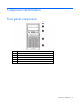
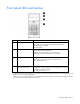
Component identification Front panel components Item Description 1 Optical drive (optional) 2 Media drive bay 3 Power On/Standby button and system power LED 4 USB connectors 5 Drive bays (inside) Component identification 6
Front panel LEDs and buttons Item Description Status 1 UID button/LED Solid blue = Activated Flashing blue (1 Hz/cycle per sec) = Remote management or firmware upgrade in progress Off = Deactivated 2 Health LED Solid green = Normal Flashing amber = System degraded Flashing red (1 Hz/cycle per sec) = System critical Fast-flashing red (4 Hz/cycles per sec) = Power fault* 3 NIC status LED Solid green = Link to network Flashing green (1 Hz/cycle per sec) = Network active Off = No network activity 4
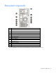
Rear panel components Item Description 1 Power supply 2 Kensington security slot 3 Slot 4 PCIe x16 (8, 4, 1)* 4 Slot 3 PCIe x8 (8, 4, 1)* 5 Slot 2 PCIe x8 (1)* 6 Slot 1 PCIe x4 (1)* 7 Serial connector 8 Video connector 9 Dedicated iLO port 10 USB 3.0 connectors 11 UID LED/button 12 NIC connectors * For more information on the expansion slot specifications, see "PCIe expansion slot definitions.
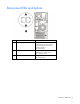
Rear panel LEDs and buttons Item Description Status 1 UID button/LED Solid blue = Activated Flashing blue (1 Hz/cycle per sec) = Remote management or firmware upgrade in progress Off = Deactivated 2 NIC status LED Solid Green = Activity exists Flashing green = Activity exists Off = No activity exists 3 NIC link LED Solid green = Link exists Off = No link exists Component identification 9
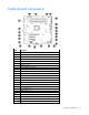
System board components Item Description 1 RPS connector 2 Processor socket 3 TPM connector 4 System battery 5 24-pin power supply connector 6 Mini-SAS connector 7 SATA connectors 8 Internal USB cable connector 9 Internal USB connector 10 Micro SD card slot 11 Front USB connector 2 12 Front USB connector 1 13 Front panel connector 14 Front system fan connector (fan 2) 15 Ambient thermal sensor connector 16 NMI header 17 System maintenance switch 18 Slot 1 PCIe2 x4 (1)*
* For more information on the expansion slot specifications, see "PCIe expansion slot definitions." DIMM slot locations DIMM slots are numbered 1 through 4. Letters are used for AMP mode DIMM ordering.
CAUTION: Clearing CMOS and/or NVRAM deletes configuration information. Be sure to properly configure the server or data loss could occur. NMI functionality An NMI crash dump creates a crash dump log before resetting a system which is not responding. Crash dump log analysis is an essential part of diagnosing reliability problems, such as failures of operating systems, device drivers, and applications. Many crashes freeze a system, and the only available action for administrators is to restart the system.
• Eight-bay SFF drive model Hot-plug drive LED definitions Item LED Status Definition 1 Locate Solid blue The drive is being identified by a host application. Flashing blue The drive carrier firmware is being updated or requires an update. Rotating green Drive activity Off No drive activity Solid white Do not remove the drive. Removing the drive causes one or more of the logical drives to fail. Off Removing the drive does not cause a logical drive to fail.
Item LED Status Definition Solid amber The drive has failed. Off The drive is not configured by a RAID controller. FBWC module LED definitions The FBWC module has three single-color LEDs (one amber and two green). The LEDs are duplicated on the reverse side of the cache module to facilitate status viewing. 1 - Amber 2 - Green 3 - Green Interpretation Off Off Off The cache module is not powered. Off Flashing 0.5 Hz Flashing 0.
1 - Amber 2 - Green 3 - Green Interpretation On On On The cache module microcontroller has failed.
Operations Power up the server 1. Connect each power cord to the server. 2. Connect each power cord to the power source. 3. Press the Power On/Standby button. The server exits standby mode and applies full power to the system. The system power LED changes from amber to green. Power down the server Before powering down the server for any upgrade or maintenance procedures, perform a backup of critical server data and programs.
Unlock the tower bezel The tower bezel must be unlocked and opened to access the drive cage and media bays. It must be unlocked to remove the access panel. The bezel must remain closed during normal server operations. Remove the tower bezel 1. Unlock the tower bezel (on page 17). 2. Open the tower bezel. 3. Pull the bezel away from the front chassis. Install the tower bezel 1. Insert the tabs on the tower bezel to the slots on the front chassis.
2. Close and lock the tower bezel. Remove the access panel WARNING: To reduce the risk of personal injury from hot surfaces, allow the drives and the internal system components to cool before touching them. CAUTION: For proper cooling, do not operate the server without the access panel, baffles, expansion slot covers, or blanks installed. If the server supports hot-plug components, minimize the amount of time the access panel is open. 1. Power down the server (on page 16). 2. Remove all power: a.
c. Lift the access panel away from the chassis. Install the access panel 1. Install the access panel: a. Place the access panel on the chassis, and slide it toward the front of the server. b. Tighten the thumbscrew. 2. Close and lock the tower bezel. Remove the air baffle CAUTION: For proper cooling, do not operate the server without the access panel, baffles, expansion slot covers, or blanks installed. If the server supports hot-plug components, minimize the amount of time the access panel is open.
1. Power down the server (on page 16). 2. Remove all power: a. Disconnect each power cord from the power source. b. Disconnect each power cord from the server. 3. Unlock the tower bezel (on page 17). 4. Remove the access panel (on page 18). 5. Remove the air baffle. Install the air baffle 1. Insert the tabs on the baffle into the slots on the rear chassis. 2. Push the front end of the baffle inside the chassis. 3. Install the access panel (on page 19).
4. Lock the tower bezel. 5. Power up the server (on page 16).
Setup Optional installation services Delivered by experienced, certified engineers, HP Care Pack services help you keep your servers up and running with support packages tailored specifically for HP ProLiant systems. HP Care Packs let you integrate both hardware and software support into a single package. A number of service level options are available to meet your needs.
Space and airflow requirements Leave at least a 7.6-cm (3-inch) clearance space at the front and back of the server for proper ventilation. Temperature requirements To ensure continued, safe, and reliable equipment operation, install or position the system in a well-ventilated, climate-controlled environment. The maximum recommended TMRA for most server products is 35°C (95°F). The temperature in the room where the server is located must not exceed 35°C (95°F).
includes a nondetachable cord that is wired to an industrial-style plug. NEMA locking-style plugs or those complying with IEC 60309 are considered suitable for this purpose. Using common power outlet strips for the server is not recommended. Server warnings and cautions WARNING: This server is very heavy. To reduce the risk of personal injury or damage to the equipment: • Observe local occupational health and safety requirements and guidelines for manual material handling.
WARNING: To reduce the risk of personal injury or equipment damage when unloading a rack: • At least two people are needed to safely unload the rack from the pallet. An empty 42U rack can weigh as much as 115 kg (253 lb), can stand more than 2.1 m (7 ft) tall, and might become unstable when being moved on its casters. • Never stand in front of the rack when it is rolling down the ramp from the pallet. Always handle the rack from both sides.
WARNING: This server is very heavy. To reduce the risk of personal injury or damage to the equipment: • Observe local occupational health and safety requirements and guidelines for manual material handling. • Get help to lift and stabilize the product during installation or removal, especially when the product is not fastened to the rails. HP recommends that a minimum of two people are required for all rack server installations.
a. Connect the Ethernet cable between the network connector on the server and a network jack. b. Press the Power On/Standby button. c. During server POST, press the F10 key. d. Complete the initial Preferences and Registration portion of Intelligent Provisioning (on page 68). e. At the 1 Start screen, click the Configure and Install button. f. • To finish the installation, follow the onscreen prompts. An Internet connection is required to update the firmware and systems software.
Hardware options installation Introduction If more than one option is being installed, read the installation instructions for all the hardware options and identify similar steps to streamline the installation process. WARNING: To reduce the risk of personal injury from hot surfaces, allow the drives and the internal system components to cool before touching them. CAUTION: To prevent damage to electrical components, properly ground the server before beginning any installation procedure.
4. Remove the drive carrier. 5. Remove the two metal brackets from the drive carrier. 6. Install the drive in the carrier.
7. Install the drive. 8. Close and lock the tower bezel. 9. Connect each power cord to the server. 10. Connect each power cord to the power source. 11. Power up the server (on page 16). Installing a hot-plug drive CAUTION: To prevent improper cooling and thermal damage, do not operate the server unless all bays are populated with either a component or a blank. To install the component: 1. Remove the tower bezel (on page 17). 2. Remove the drive blank. 3. Retain the blank for future use.
4. Prepare the drive. 5. Install the drive. 6. Determine the status of the drive from the drive LED definitions. 7. Close and lock the tower bezel. Drive cage options Four-bay LFF hot-plug drive backplane option To install the component: 1. Power down the server (on page 16). 2. Remove all power: a. Disconnect each power cord from the power source. b. Disconnect each power cord from the server. 3. Remove the tower bezel (on page 17).
4. Remove the access panel (on page 18). 5. Install the drive cage assembly. 6. Connect the drive backplane cables: a. Connect the power cable to the backplane. b. Do one of the following: — Connect the Mini-SAS cable to the system board (SATA drive support only).
For cable routing information, see "Hot-plug, SATA drive support ("Hot-plug cage to system board, SATA drive support" on page 61)." — Connect one end of the Mini-SAS cable to the backplane and the other end to an optional Smart Array controller (SATA and SAS drive support). For cable routing information, see "Hot-plug SATA and SAS drive support ("Hot-plug cage to controller card, SATA and SAS drive support" on page 61)." 7. Install the drives ("Drive options" on page 28).
12. Connect each power cord to the power source. 13. Power up the server (on page 16). Eight-bay SFF hot-plug drive cage option To install the component: 1. Power down the server (on page 16). 2. Remove all power: a. Disconnect each power cord from the power source. b. Disconnect each power cord from the server. 3. Remove the tower bezel (on page 17). 4. Remove the access panel (on page 18). 5. Remove the air baffle (on page 19). 6. Remove all installed drives. 7.
9. Install the SFF drive cage assembly. 10. Connect the drive backplane cables: a. Connect the power cable to the backplane. b. Connect the Mini-SAS cables to the backplane and to an optional Smart Array controller. For cable routing information, see "Eight-bay SFF drive cabling (on page 62)." 11. Install the drives ("Drive options" on page 28). CAUTION: To prevent improper cooling and thermal damage, do not operate the server unless all bays are populated with either a component or a blank. 12.
16. Connect each power cord to the power source. 17. Power up the server (on page 16). Controller options The server includes an embedded Smart Array B120i controller. For more information about the controller and its features, see the HP Dynamic Smart Array RAID Controller User Guide on the HP website (http://www.hp.com/support/DSA_RAID_UG_en). To configure arrays, see the Configuring Arrays on HP Smart Array Controllers Reference Guide on the HP website (http://www.hp.com/support/CASAC_RG_en).
2. Remove all power: a. Disconnect each power cord from the power source. b. Disconnect each power cord from the server. 3. Unlock the tower bezel (on page 17). 4. Remove the access panel (on page 18). 5. Remove the air baffle (on page 19). 6. If necessary, disconnect the Mini-SAS cable from the system board. 7. Install the storage controller. 8. Connect all necessary internal and external cabling to the option.
6. Install the cache module on the storage controller. 7. Connect the capacitor pack cable to the cache module. 8. Install the storage controller ("Installing a storage controller" on page 36).
9. Install the capacitor pack. For cable routing, see capacitor pack cabling. 10. Install the air baffle (on page 20). 11. Install the access panel (on page 19). 12. Lock the tower bezel. 13. Connect each power cord to the server. 14. Connect each power cord to the power source. 15. Power up the server (on page 16). Optical drive option To install the component: 1. Power down the server (on page 16). 2. Remove all power: a. Disconnect each power cord from the power source. b.
5. Remove the media bay blank. 6. Remove the EMI shield. 7. Attach the screws to the optical drive.
8. Install the optical drive into the media drive bay ("Optical drive cabling" on page 62). 9. Connect the drive cables: a. Connect the power cable to the drive. b. Connect one end of the SATA cable to the drive and the other end to the system board. For cable routing information, see "Optical drive cabling (on page 62)." 10. Install the access panel (on page 19). 11. Install the tower bezel (on page 17). 12. Connect each power cord to the server. 13. Connect each power cord to the power source.
IMPORTANT: This server does not support mixing LRDIMMs, RDIMMs, or UDIMMs. Attempting to mix any combination of these DIMMs can cause the server to halt during BIOS initialization. The server supports single- and dual-rank UDIMMs operating at a speed of up to 1600 MHz. Depending on the processor model and the number of DIMMs installed, the memory clock speed might be reduced to 1333 or 1066 MHz. The server supports a maximum system memory of 32 GB, using 2-GB, 4-GB, and 8-GB UDIMMs.
Item Description Definition 4 Voltage rating L = Low voltage (1.35V) U = Ultra low voltage (1.25V) Blank or omitted = Standard 5 Memory speed 12800 = 1600-MT/s 10600 = 1333-MT/s 8500 = 1066-MT/s 6 DIMM type R = RDIMM (registered) E = UDIMM (unbuffered with ECC) L = LRDIMM (load reduced) For the latest supported memory information, see the QuickSpecs on the HP website (http://h18000.www1.hp.com/products/quickspecs/ProductBulletin.html).
General DIMM slot population guidelines • The server has four DIMM slots. • The server supports two channels with two DIMM slots per channel. o Memory channel 1 consists of the two DIMMs that are closest to the processor. o Memory channel 2 consists of the two DIMMs that are farthest from the processor. • A white DIMM slot indicates the first slot of a channel (2-A, 4-B). • Memory speed support depends on the type of processor installed.
7. Install the DIMM. 8. Install the air baffle (on page 20). 9. Install the access panel (on page 19). 10. Lock the tower bezel. 11. Connect each power cord to the server. 12. Connect each power cord to the power source. 13. Power up the server (on page 16). After installing the DIMMs, to configure memory protection mode, use RBSU ("HP ROM-Based Setup Utility" on page 71). Expansion board options The server has both full-height and low-profile expansion slots.
6. Remove the expansion slot cover retainer. 7. Identify the expansion slot compatible with the new option, and then remove the cover opposite that slot.
8. If installing a full-length expansion board, remove the board retainer. 9. Install the expansion board.
10. If installing a full-length expansion board, install the board retainer that was removed. 11. Install the expansion slot cover retainer. 12. Connect all necessary internal and external cables to the expansion board. For more information on these cabling requirements, see the documentation that ships with the option. 13. Install the air baffle (on page 20). 14. Install the access panel (on page 19). 15. Lock the tower bezel. 16. Connect each power cord to the server. 17.
HP Trusted Platform Module option For more information about product features, specifications, options, configurations, and compatibility, see the product QuickSpecs on the HP Product Bulletin website (http://www.hp.com/go/productbulletin). Use these instructions to install and enable a TPM on a supported server. This procedure includes three sections: 1. Installing the Trusted Platform Module board. 2. Retaining the recovery key/password (on page 51). 3.
2. Unlock the tower bezel (on page 17). 3. Remove the access panel (on page 18). 4. Remove the air baffle (on page 19). CAUTION: Any attempt to remove an installed TPM from the system board breaks or disfigures the TPM security rivet. Upon locating a broken or disfigured rivet on an installed TPM, administrators should consider the system compromised and take appropriate measures to ensure the integrity of the system data. 5. Install the TPM board. Press down on the connector to seat the board. 6.
12. Power up the server (on page 16). Retaining the recovery key/password The recovery key/password is generated during BitLocker™ setup, and can be saved and printed after BitLocker™ is enabled. When using BitLocker™, always retain the recovery key/password. The recovery key/password is required to enter Recovery Mode after BitLocker™ detects a possible compromise of system integrity.
2. Remove all power: a. Disconnect each power cord from the power source. b. Disconnect each power cord from the server. 3. Remove the tower bezel (on page 17). 4. Remove the access panel (on page 18). 5. Disconnect all power cables from the drives and system board. 6. Remove the power supply. 7. Disconnect all cables from installed media drives. 8. Remove all installed devices and any EMI shields from the media drive bays.
9. Install the RPS cage. 10. Insert the RPS backplane module cables into the media drive cage, and then slide the module into the lower media drive bay. Align the left edge of the module with the guide mark on the bay. 11. Connect the eight-pin to four-pin adapter cable to the eight-pin power supply connector of the RPS backplane module. 12. Connect the RPS cables to the system board. For detailed cabling information, see "Redundant power supply cabling.
13. Install an HP common slot power supply in the upper bay of the RPS cage. CAUTION: In a redundant power supply configuration, both power supply modules in the server must have the same output power capacity. Verify that all power supplies have the same part number and label color. The system becomes unstable and might shut down when it detects mismatched power supplies. 14. For improved power efficiency and redundancy, install two HP common slot power supplies: a. Remove the EMI shield.
b. Install the HP common slot power supplies. 15. Install any device originally installed in the upper media drive bay. 16. Install the EMI shield in the lower media drive bay. 17. Install the access panel (on page 19). 18. If the lower media bay blank is not attached to the tower bezel, install it. 19. Lock the tower bezel. 20. Connect each power cord to the server. 21. Connect each power cord to the power source. 22. Power up the server (on page 16).
To establish a simple Ethernet connection: 1. Connect an Ethernet cable to the switch, and then connect the cable to a network jack. 2. Connect an Ethernet cable to the server NIC connector 1 or 2. 3. Connect the cable to any switch network port. To establish an Ethernet connection with iLO functionality by using the dedicated iLO connector: 1. Connect an Ethernet cable to the switch, and then connect the cable to a network jack. 2.
2. Under the Network menu, select the NIC and TCP/IP option. 3. Set the Network Interface Adapter field to Shared Network Port — LOM. 4. To save the change, press F10. 5. To close the iLO RBSU, under the File menu, select the Exit option.
6. Connect an Ethernet cable to the switch, and then connect the cable to a network jack. 7. Connect an Ethernet cable to the server NIC 1/shared iLO connector, and then connect the cable to any switch network port. Completing the switch Self-Test 1. Connect the power adapter to the switch. 2. Connect the power adapter to the AC power source. 3. Check the status of the switch Power LED. This LED is solid green to indicate that the power connection is established. 4.
Cabling Cabling overview This section provides guidelines to help make informed decisions about cabling the server and hardware options to optimize performance. For information on cabling peripheral components, see the white paper on high-density deployment at the HP website (http://www.hp.com/products/servers/platforms). CAUTION: When routing cables, always be sure that the cables are not in a position where they can be pinched or crimped.
Storage cabling Four-bay LFF drive cabling Non-hot-plug cage to system board, SATA drive support only Item Description 1 Drive cage power cable 2 Mini-SAS cable Non-hot-plug cage to controller card, SATA and SAS drive support Item Description 1 Drive cage power cable Cabling 60
Item Description 2 Mini-SAS cable Hot-plug cage to system board, SATA drive support Item Description 1 Drive cage power cable 2 Mini-SAS cable Hot-plug cage to controller card, SATA and SAS drive support Item Description 1 Drive cage power cable 2 Mini-SAS cable Cabling 61
Eight-bay SFF drive cabling This drive configuration supports hot-plug SATA and SAS drives.
Item Description 1 Optical drive power cable 2 SATA cable • Optical drive in a redundant power configuration Item Description 1 SATA cable 2 Drive cage power cable 3 Optical drive power cable Cabling 63
Power supply cabling Integrated power supply cabling Item Description 1 4-pin power supply cable 2 24-pin power supply cable Redundant power supply cabling Item Description 1 4-pin power supply cable (with the 8-pin to 4-pin adapter cable connected) 2 26-pin RPS cable Cabling 64
Item Description 3 24-pin power supply cable Capacitor pack cabling Item Description 1 Cache module 2 FBWC capacitor pack Cabling 65
Software and configuration utilities Server mode The software and configuration utilities presented in this section operate in online mode, offline mode, or in both modes.
iLO enables and manages the Active Health System (on page 67) and also features Agentless Management. All key internal subsystems are monitored by iLO. SNMP alerts are sent directly by iLO regardless of the host operating system or even if no host operating system is installed. HP Insight Remote Support software (on page 70) is also available in HP iLO with no operating system software, drivers, or agents.
The data that is collected is managed according to the HP Data Privacy policy. For more information see the HP website (http://www.hp.com/go/privacy). The Active Health System log, in conjunction with the system monitoring provided by Agentless Management or SNMP Pass-thru, provides continuous monitoring of hardware and configuration changes, system status, and service alerts for various server components. The Agentless Management Service is available in the SPP, which is a disk image (.
HP Insight Diagnostics HP Insight Diagnostics is a proactive server management tool, available in both offline and online versions, that provides diagnostics and troubleshooting capabilities to assist IT administrators who verify server installations, troubleshoot problems, and perform repair validation. HP Insight Diagnostics Offline Edition performs various in-depth system and component testing while the OS is not running. To run this utility, boot the server using Intelligent Provisioning (on page 68).
HP Insight Remote Support software HP strongly recommends that you install HP Insight Remote Support software to complete the installation or upgrade of your product and to enable enhanced delivery of your HP Warranty, HP Care Pack Service, or HP contractual support agreement.
SPP has several key features for updating HP ProLiant servers. Using HP SUM as the deployment tool, SPP can be used in an online mode on a Windows or Linux hosted operating system, or in an offline mode where the server is booted to the ISO so that the server can be updated automatically with no user interaction or updated in interactive mode. For more information or to download SPP, see the HP website (http://www.hp.com/go/spp).
For more information on RBSU, see the HP ROM-Based Setup Utility User Guide on the Documentation CD or the HP website (http://www.hp.com/support/rbsu). Using RBSU To use RBSU, use the following keys: • To access RBSU, press the F9 key during power-up when prompted. • To navigate the menu system, use the arrow keys. • To make selections, press the Enter key. • To access Help for a highlighted configuration option, press the F1 key.
Boot options Near the end of the boot process, the boot options screen is displayed. This screen is visible for several seconds before the system attempts to boot from a supported boot device. During this time, you can do the following: • Access RBSU by pressing the F9 key. • Access Intelligent Provisioning Maintenance Menu by pressing the F10 key. • Access the boot menu by pressing the F11 key. • Force a PXE Network boot by pressing the F12 key.
o Advanced Capacity Expansion (SATA to SAS and SAS to SATA) o Offline Split Mirror o RAID 6 and RAID 60 o RAID 1 (ADM) and RAID 10 (ADM) o HP Drive Erase o Video-On-Demand Advanced Controller Settings • Provides different operating modes, enabling faster configuration or greater control over the configuration options • Remains available any time that the server is on • Displays on-screen tips for individual steps of a configuration procedure • Provides context-sensitive searchable help co
For more information about the controller and its features, see the HP Smart Array Controllers for HP ProLiant Servers User Guide on the HP website (http://www.hp.com/support/SAC_UG_ProLiantServers_en). To configure arrays, see the Configuring Arrays on HP Smart Array Controllers Reference Guide on the HP website (http://www.hp.com/support/CASAC_RG_en). ROMPaq utility The ROMPaq utility enables you to upgrade the system firmware (BIOS).
Redundant ROM support The server enables you to upgrade or configure the ROM safely with redundant ROM support. The server has a single ROM that acts as two separate ROM images. In the standard implementation, one side of the ROM contains the current ROM program version, while the other side of the ROM contains a backup version. NOTE: The server ships with the same version programmed on each side of the ROM.
• VCRM manages the repository for SPP. Administrators can view the SPP contents or configure VCRM to automatically update the repository with internet downloads of the latest software and firmware from HP. • VCA compares installed software versions on the node with updates available in the VCRM managed repository. Administrators configure VCA to point to a repository managed by VCRM.
Troubleshooting Troubleshooting resources The HP ProLiant Gen8 Troubleshooting Guide, Volume I: Troubleshooting provides procedures for resolving common problems and comprehensive courses of action for fault isolation and identification, issue resolution, and software maintenance on ProLiant servers and server blades. To view the guide, select a language: • English (http://www.hp.com/support/ProLiant_TSG_v1_en) • French (http://www.hp.com/support/ProLiant_TSG_v1_fr) • Spanish (http://www.hp.
System battery replacement If the server no longer automatically displays the correct date and time, then replace the battery that provides power to the real-time clock. Under normal use, battery life is 5 to 10 years. WARNING: The computer contains an internal lithium manganese dioxide, a vanadium pentoxide, or an alkaline battery pack. A risk of fire and burns exists if the battery pack is not properly handled. To reduce the risk of personal injury: • • • • Do not attempt to recharge the battery.
For more information about battery replacement or proper disposal, contact an authorized reseller or an authorized service provider.
Regulatory information Safety and regulatory compliance For safety, environmental, and regulatory information, see Safety and Compliance Information for Server, Storage, Power, Networking, and Rack Products, available at the HP website (http://www.hp.com/support/Safety-Compliance-EnterpriseProducts). Turkey RoHS material content declaration Ukraine RoHS material content declaration Warranty information HP ProLiant and X86 Servers and Options (http://www.hp.
Electrostatic discharge Preventing electrostatic discharge To prevent damaging the system, be aware of the precautions you need to follow when setting up the system or handling parts. A discharge of static electricity from a finger or other conductor may damage system boards or other static-sensitive devices. This type of damage may reduce the life expectancy of the device. To prevent electrostatic damage: • Avoid hand contact by transporting and storing products in static-safe containers.
Specifications Environmental specifications Specification Value Temperature range* Operating 10° C to 35° C (50° F to 95° F) Nonoperating -30° C to 60° C (-22° F to 140° F) Relative humidity (noncondensing) Operating, maximum wet bulb 10% to 90% temperature of 28°C (82.4°F) Nonoperating, maximum wet 5% to 95% bulb temperature of 38.7°C (101.7°F) * All temperature ratings shown are for sea level. An altitude derating of 1° C per 304.8 m (1.8° F per 1,000 ft) to 3048 m (10,000 ft) is applicable.
CAUTION: Check the system and power supply input ratings before powering up the server.
Hot-plug power supply calculations For hot-plug power supply specifications and calculators to determine electrical and heat loading for the server, see the HP Power Advisor website (http://www.hp.com/go/hppoweradvisor).
Support and other resources Before you contact HP Be sure to have the following information available before you call HP: • Active Health System log (HP ProLiant Gen8 or later products) Download and have available an Active Health System log for 3 days before the failure was detected. For more information, see the HP iLO 4 User Guide or HP Intelligent Provisioning User Guide on the HP website (http://www.hp.com/go/ilo/docs).
providers or service partners) identifies that the repair can be accomplished by the use of a CSR part, HP will ship that part directly to you for replacement. There are two categories of CSR parts: • Mandatory—Parts for which customer self repair is mandatory. If you request HP to replace these parts, you will be charged for the travel and labor costs of this service. • Optional—Parts for which customer self repair is optional. These parts are also designed for customer self repair.
Pour plus d'informations sur le programme CSR de HP, contactez votre Mainteneur Agrée local. Pour plus d'informations sur ce programme en Amérique du Nord, consultez le site Web HP (http://www.hp.com/go/selfrepair). Riparazione da parte del cliente Per abbreviare i tempi di riparazione e garantire una maggiore flessibilità nella sostituzione di parti difettose, i prodotti HP sono realizzati con numerosi componenti che possono essere riparati direttamente dal cliente (CSR, Customer Self Repair).
HINWEIS: Einige Teile sind nicht für Customer Self Repair ausgelegt. Um den Garantieanspruch des Kunden zu erfüllen, muss das Teil von einem HP Servicepartner ersetzt werden. Im illustrierten Teilekatalog sind diese Teile mit „No“ bzw. „Nein“ gekennzeichnet. CSR-Teile werden abhängig von der Verfügbarkeit und vom Lieferziel am folgenden Geschäftstag geliefert. Für bestimmte Standorte ist eine Lieferung am selben Tag oder innerhalb von vier Stunden gegen einen Aufpreis verfügbar.
sustituciones que lleve a cabo el cliente, HP se hará cargo de todos los gastos de envío y devolución de componentes y escogerá la empresa de transporte que se utilice para dicho servicio. Para obtener más información acerca del programa de Reparaciones del propio cliente de HP, póngase en contacto con su proveedor de servicios local. Si está interesado en el programa para Norteamérica, visite la página web de HP siguiente (http://www.hp.com/go/selfrepair).
Opcional – Peças cujo reparo feito pelo cliente é opcional. Essas peças também são projetadas para o reparo feito pelo cliente. No entanto, se desejar que a HP as substitua, pode haver ou não a cobrança de taxa adicional, dependendo do tipo de serviço de garantia destinado ao produto. OBSERVAÇÃO: Algumas peças da HP não são projetadas para o reparo feito pelo cliente. A fim de cumprir a garantia do cliente, a HP exige que um técnico autorizado substitua a peça.
Support and other resources 92
Support and other resources 93
Acronyms and abbreviations ABEND abnormal end ACU Array Configuration Utility AMP Advanced Memory Protection ASR Automatic Server Recovery BMC baseboard management controller BSMI Bureau of Standards, Metrology and Inspection CE Conformité Européenne (European Conformity) CSA Canadian Standards Association CSR Customer Self Repair DDR double data rate EMI electromagnetic interference FBWC flash-backed write cache Acronyms and abbreviations 94
FCC Federal Communications Commission HP CS HP Common Slot (power supply) HP SIM HP Systems Insight Manager HP SUM HP Smart Update Manager IEC International Electrotechnical Commission iLO Integrated Lights-Out IML Integrated Management Log ISO International Organization for Standardization LFF large form factor LRDIMM load reduced dual in-line memory module NMI nonmaskable interrupt NVRAM nonvolatile memory ORCA Option ROM Configuration for Arrays PCIe Peripheral Component Interconnect Express
PDU power distribution unit POST Power-On Self Test PXE preboot execution environment RBSU ROM-Based Setup Utility RDIMM registered dual in-line memory module RDP Rapid Deployment Pack RF radio frequency RFI radio frequency interference RPS redundant power supply SAS serial attached SCSI SATA serial ATA SD Secure Digital SFF small form factor SPP HP Service Pack for ProLiant Acronyms and abbreviations 96
TMRA recommended ambient operating temperature TPM Trusted Platform Module UDIMM unregistered dual in-line memory module UID unit identification USB universal serial bus VCA Version Control Agent VCRM Version Control Repository Manager xHCI Extensible Host Controller Interface Acronyms and abbreviations 97
Documentation feedback HP is committed to providing documentation that meets your needs. To help us improve the documentation, send any errors, suggestions, or comments to Documentation Feedback (mailto:docsfeedback@hp.com). Include the document title and part number, version number, or the URL when submitting your feedback.
Index A access panel 18, 19 air baffle 19, 20 Array Configuration Utility (ACU) 73 ASR (Automatic Server Recovery) 75 authorized reseller 86 auto-configuration process 72 Automatic Server Recovery (ASR) 75 B battery 79 battery, installing 79 bezel 17 BIOS upgrade 66, 75 boot options 27, 73 BSMI notice 81 buttons 6 buttons, front panel 6 C cables 59 cabling 59, 60, 62, 63, 64 cache module 14 Canadian notice 81 capacitor pack cabling 64 Care Pack 22, 70, 77 Change Control 77 components 6 components, front p
HP Smart Update Manager overview 66, 71 HP technical support 77, 86 I iLO (Integrated Lights-Out) 66, 67, 68 IML (Integrated Management Log) 66, 68 Insight Diagnostics 69, 76 Insight Remote Support Software 70 installation services 22, 25 installation, server options 25, 28 installing hardware 25, 28 installing the server into the rack 25 Integrated Lights-Out (iLO) 66, 68 Integrated Management Log (IML) 68 Intelligent Provisioning 66, 68, 69 J Japanese notice 81 L P PCI expansion slots 11 phone numbers
server warnings and cautions 24 Service Packs 70 shipping carton contents 25 Smart Update Manager 66, 71 software 76, 77 space and airflow requirements 23 specifications 83, 85 specifications, environmental 83 specifications, power 83 specifications, server 83 static electricity 82 storage controller 36 support 86 supported operating systems 77 switch, system maintenance 11 system battery 79 system board components 10 system components 6 system configuration settings 11, 76 system maintenance switch 11 T T