
HP ProLiant ML310e Gen8 v2 Server Maintenance and Service Guide


Removal and replacement procedures 51
Integrated power supply
To remove the component:
1. Power down the server (on page 27).
2. Remove all power:
a. Disconnect each power cord from the power source.
b. Disconnect each power cord from the server.
3. Unlock the tower bezel (on page 26).
4. Remove the access panel ("Access panel" on page 28).
WARNING: To reduce the risk of personal injury from hot surfaces, allow the power supply or
power supply blank to cool before touching it.
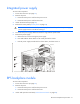
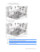
5. Disconnect the power supply cables from the drive cage and the system board.
6. Remove the power supply:
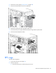
a. Remove the four screws securing the power supply.
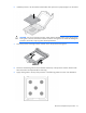
b. Press and hold the release button on the inside panel of the chassis.
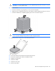
c. Push the power supply towards the front of the chassis, and then remove it.
To replace the component, reverse the removal procedure.
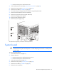
RPS backplane module
To remove the component:
1. Power down the server (on page 27).
2. Remove all power:
a. Disconnect each power cord from the power source.
b. Disconnect each power cord from the server.
3. Unlock and open the tower bezel ("Unlock the tower bezel" on page 26).