Compaq ProLiant ML350 Generation 2 Server Maintenance and Service Guide Part Number 236634-002 Spare Part Number 250840-001 May 2002 (Second Edition) This document provides detailed instructions for maintenance and service personnel. It includes removal and replacement procedures, spare parts information and an overview of diagnostic tools for the Compaq ProLiant ML350 Generation 2 server.
© 2002 Compaq Information Technologies Group, L.P. Compaq, the Compaq logo, Compaq Insight Manager, ProLiant, QuickFind, SmartStart and ROMPaq are trademarks of Compaq Information Technologies Group, L.P. in the U.S. and/or other countries. Microsoft, Windows, and Windows NT are trademarks of Microsoft Corporation in the U.S. and/or other countries. Intel and Pentium are trademarks of Intel Corporation in the U.S. and/or other countries.
Contents About This Guide Symbols in Text............................................................................................................................................ v Important Safety Information ....................................................................................................................... v Compaq Technician Notes............................................................................................................................
Contents Removable Media Device ....................................................................................................................... 2-21 Expansion Slots ....................................................................................................................................... 2-23 Expansion Board ..................................................................................................................................... 2-24 Memory Module Guidelines .................
About This Guide This maintenance and service guide can be used for reference when servicing Compaq ProLiant ML350 Generation 2 servers. WARNING: To reduce the risk of personal injury from electric shock and hazardous energy levels, only authorized service technicians should attempt to repair this equipment. Improper repairs can create conditions that are hazardous. Symbols in Text These symbols may be found in the text of this guide. They have the following meanings.
About This Guide WARNING: To reduce the risk of personal injury from electric shock and hazardous energy levels, do not exceed the level of repairs specified in these procedures. Because of the complexity of the individual boards and subassemblies, do not attempt to make repairs at the component level or to make modifications to any printed wiring board. Improper repairs can create conditions that are hazardous.
About This Guide Where to Go for Additional Help In addition to this guide, the following information sources are available: • User documentation • Compaq Service Quick Reference Guide • Service training guides • Compaq service advisories and bulletins • Compaq QuickFind™ information services • Compaq Insight Manager software For additional copies, visit the Compaq website: www.compaq.
About This Guide viii • Monospace typeface is used for command lines, code examples, screen displays, error messages, and user input. • Sans serif typeface is used for uniform resource locators (URLs).
1 Illustrated Parts Catalog This chapter provides the illustrated parts breakdown and spare parts lists for the Compaq ProLiant™ ML350 Generation 2 server. See Table 1-1, Mechanical Spare Parts List, and Table 1-2, System Components Spare Parts List, for the names of referenced spare parts.
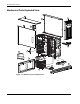
Illustrated Parts Catalog Mechanical Parts Exploded View 2c 1 2a 2b 6 10 7 5a 8 5b 5b 9 4 3 Figure 1-1: Mechanical parts exploded view 1-2 Compaq ProLiant ML350 Generation 2 Server Maintenance and Service Guide COMPAQ CONFIDENTIAL Codename: Forge Part Number: 236634-002 Last Saved On: 5/14/02 11:56 AM
Illustrated Parts Catalog Mechanical Spare Parts List Table 1-1: Mechanical Spare Parts List Item Description Spare Part Number Chassis 1 Bezel door (tower model only) 249927-001 2 Cover kit 216104-001 a) Hood panel (tower model only) b) Access panel c) Top panel 3 Hot-plug hard drive cage 230995-001 4 Hot-plug hard drive blank 122759-001 5 Miscellaneous plastics kit 250843-001 a) Expansion board retainer b) Feet (4) (tower model only) c) Expansion board guide* d) Retainer clips* e) Power
Illustrated Parts Catalog System Components Exploded View 19 11 15 5e 16 14 12 21 20 18 13 23 17 24 23 Figure 1-2: System components exploded view 1-4 Compaq ProLiant ML350 Generation 2 Server Maintenance and Service Guide COMPAQ CONFIDENTIAL Codename: Forge Part Number: 236634-002 Last Saved On: 5/14/02 11:56 AM
Illustrated Parts Catalog System Components Spare Parts List Table 1-2: System Components Spare Parts List Item Description Spare Part Number 5e Power supply backplane board cover (part of plastics kit) 250843-001 11 System fan module 249925-001 Boards 12 System board 249930-001 13 Server Feature Board 249933-001 14 Power supply backplane board 249924-001 Mass Storage Devices 15 IDE CD-ROM drive 233408-001 16 Diskette drive 233409-001 17 Hot-plug hard drive cage 230995-001 Power
Illustrated Parts Catalog Table 1-2: System Components Spare Parts List continued Item Description Spare Part Number Miscellaneous 28 Enhanced keyboard (carbon)* 244000-001 29 Signal cable kits* 163353-001 a) IDE ribbon cable assembly b) Diskette drive cable assembly c) Removable media device SCSI cable 30 SCSI LVD cable* 249931-001 31 Return kit (tower model only)* 249929-001 32 Return kit (rack model only)* 250189-001 33 Country kit* 249932-001 34 Tower-to-rack conversion kit* 2508
2 Removal and Replacement Procedures This chapter provides subassembly/module-level removal and replacement procedures for the Compaq ProLiant ML350 Generation 2 server. Run the diagnostics program to be sure that all components operate properly. To service the server, you may need a Torx T-15 screwdriver.
Removal and Replacement Procedures Electrostatic Discharge Information An electrostatic discharge (ESD) can damage static-sensitive devices or microcircuitry. Proper packaging and grounding techniques are necessary precautions to prevent damage. To prevent electrostatic damage, observe the following precautions: 2-2 • Transport products in static-safe containers such as conductive tubes, bags, or boxes. • Keep electrostatic-sensitive parts in their containers until they arrive at static-free stations.
Removal and Replacement Procedures Symbols on Equipment These symbols may be located on equipment in areas where hazardous conditions may exist. WARNING: This symbol, in conjunction with any of the following symbols, indicates the presence of a potential hazard. The potential for injury exists if warnings are not observed. Consult your documentation for specific details. This symbol indicates the presence of hazardous energy circuits or electric shock hazards. Refer all servicing to qualified personnel.
Removal and Replacement Procedures Preparation Procedures WARNING: Only authorized technicians trained by Compaq should attempt to repair this equipment. Because of the complexity of the individual boards and subassemblies, no one should attempt to make repairs at the component level or to make modifications to any printed wiring board. Improper repairs can create a safety hazard. CAUTION: Electrostatic discharge (ESD) can damage electronic components.
Removal and Replacement Procedures 2. Be sure that the system LED closest to the right on the front panel is amber and that the fan noise has stopped. 3. Disconnect the AC power cord from the AC outlet, and then from the server. 4. Disconnect all external peripheral devices from the server. Rack Stability Warning For stability and safety, properly positioning the server is critical.
Removal and Replacement Procedures Bezel Door (Tower) To remove the bezel door: 1. Complete the preparation procedures. Refer to “Preparation Procedures” earlier in this chapter. 2. If the keylock is locked, unlock the bezel door using the included key (1). 3. Open the bezel door fully to the right (2). 4. Lift the bezel door, and then pull it away from the chassis (3). 3 2 1 Figure 2-1: Removing the bezel door (tower model) To replace the bezel door, reverse steps 3 and 4.
Removal and Replacement Procedures Bezel (Rack) To remove the bezel: 1. Complete the preparation procedures. Refer to “Preparation Procedures” earlier in this chapter. 2. Loosen the two thumbscrews securing the rack bezel to the chassis (1). 3. Pull the bezel up, and then pull the bezel away from the chassis (2). 1 2 Figure 2-2: Removing the bezel door (rack model) To replace the bezel door, reverse steps 2 and 3.
Removal and Replacement Procedures Access Panel To remove the access panel: 1. Complete the preparation procedures. Refer to “Preparation Procedures” earlier in this chapter. 2. Open the bezel door fully to the right. Refer to “Bezel Door” earlier in this chapter. 3. Loosen the two thumbscrews located on the left of the front chassis (1). 4. Slide back the access panel about 1.5 cm (0.5 inch), then lift and remove the panel (2).
Removal and Replacement Procedures Removable Media Device Blank IMPORTANT: To install a removable media device or a hard drive for the first time, the removable media device blank must be removed from an available removable media bay. To remove a removable media device blank from the front chassis: 1. Complete the preparation procedures. Refer to “Preparation Procedures” earlier in this chapter. 2. Open the bezel door. Refer to “Bezel Door” earlier in this chapter. 3. Remove the access panel.
Removal and Replacement Procedures Cable Routing Diagrams Figure 2-5 through Figure 2-8 illustrate the cable routing for the server. CAUTION: When routing cables, always ensure that the cables are not in a position where they can be pinched or crimped.
Removal and Replacement Procedures IDE CD-ROM Drive Signal Cable Figure 2-6: IDE CD-ROM drive signal cable routing Compaq ProLiant ML350 Generation 2 Server Maintenance and Service Guide COMPAQ CONFIDENTIAL Codename: Forge Part Number: 236634-002 Last Saved On: 5/14/02 12:00 PM 2-11
Removal and Replacement Procedures Removable Media Device Cable 2 1 Figure 2-7: Removable media device cable routing Table 2-1: Removable Media Device Cable Routing Item Description 1 Signal cable 2 Power cable SCSI LVD Cable Figure 2-8: SCSI LVD cable routing 2-12 Compaq ProLiant ML350 Generation 2 Server Maintenance and Service Guide COMPAQ CONFIDENTIAL Codename: Forge Part Number: 236634-002 Last Saved On: 5/14/02 12:00 PM
Removal and Replacement Procedures Air Baffle To remove the air baffle: 1. Complete the preparation procedures. Refer to “Preparation Procedures” earlier in this chapter. 2. Open the bezel door. Refer to “Bezel Door” earlier in this chapter. 3. Remove the access panel. Refer to “Access Panel” earlier in this chapter. 4. Loosen the thumbscrew that secures the air baffle to the server chassis (1). 5. Pull the air baffle out of the server (2).
Removal and Replacement Procedures System Fan Module To remove the system fan module: 1. Complete the preparation procedures. Refer to “Preparation Procedures” earlier in this chapter. 2. Open the bezel door. Refer to “Bezel Door” earlier in this chapter. 3. Remove the access panel. Refer to “Access Panel” earlier in this chapter. 4. Remove the air baffle. Refer to “Air Baffle” earlier in this chapter. 5. Disconnect the fan cable from the system board.
Removal and Replacement Procedures 6. Loosen the thumbscrew securing the system fan module to the chassis (1). 7. Gently pull the system fan module out and away from the chassis (2). 1 2 Figure 2-11: Removing the system fan module To replace the system fan module, reverse steps 2 through 7.
Removal and Replacement Procedures Drive Bay Configuration The server supports a maximum of ten internal drive bays (four are for removable media devices, six are for hot-plug hard drives). The removable media device bays contain a one-third height, 1.44-MB diskette drive; a one-half height IDE CD-ROM drive; and two half-height open bays.
Removal and Replacement Procedures Hot-Plug Hard Drive Blank To remove a hot-plug hard drive blank: 1. Complete the preparation procedures. Refer to “Preparation Procedures” earlier in this chapter. 2. Open the bezel door. Refer to “Bezel Door” earlier in this chapter. 3. Slide the release latch to the left (1), then pull the drive blank out of the drive bay (2). 2 1 Figure 2-13: Removing a hot-plug hard drive blank To replace a hot-plug hard drive blank, reverse steps 2 and 3.
Removal and Replacement Procedures Hot-Plug Hard Drive To remove a hot-plug hard drive: 1. Complete the preparation procedures. Refer to “Preparation Procedures” earlier in this chapter. 2. Open the bezel door. Refer to “Bezel Door” earlier in this chapter. 3. Slide the hard drive release latch (1) to open the ejector lever (2). 4. Pull the hard drive out of the drive bay.
Removal and Replacement Procedures Hot-Plug Hard Drive Cage To remove a hot-plug hard drive cage: 1. Complete the preparation procedures. Refer to “Preparation Procedures” earlier in this chapter. 2. Remove the bezel door. Refer to “Bezel Door” earlier in this chapter. 3. Remove the access panel. Refer to “Access Panel” earlier in this chapter. 4. Disconnect the power cable from the back of the hard drive cage (1). 5. Disconnect the SCSI cable from the back of the hard drive cage (2).
Removal and Replacement Procedures 6. Remove all hard drives and drive blanks. Refer to “Hot-Plug Hard Drive Blank” earlier in this chapter. 7. With a Torx T-15 screwdriver, remove the four screws securing the drive cage to the chassis (1). 8. Pull the drive cage away from the chassis (2). 1 2 1 1 Figure 2-16: Removing a hot-plug hard drive cage To replace a hot-plug hard drive cage, reverse steps 2 through 8.
Removal and Replacement Procedures Removable Media Device To remove a removable media device: 1. Complete the preparation procedures. Refer to “Preparation Procedures” earlier in this chapter. 2. Open the bezel door. Refer to “Bezel Door” earlier in this chapter. 3. Remove the access panel. Refer to “Access Panel” earlier in this chapter. 4. Disconnect the cables from the back of the removable media device.
Removal and Replacement Procedures 5. While pushing up the drivelock (1), pull the device out of the bay (2). 2 1 Figure 2-18: Removing the removable media device To replace a removable media device, insert the device into the bay until the device clicks into place. NOTE: It is not necessary to push up on the drivelock when installing a removable media device.
Removal and Replacement Procedures Expansion Slots Figure 2-19 and Table 2-3 show and describe the expansion slot locations. 1 2 3 4 5 6 Figure 2-19: Expansion slot locations Table 2-3: Expansion Slots Item Slot Slot Number 1 64-bit 33-MHz PCI, 3.3 V 1 2 64-bit 33-MHz PCI, 3.3 V 2 3 64-bit 33-MHz PCI, 3.3 V 3 4 64-bit 33-MHz PCI, 3.3 V 4 5 64-bit 33-MHz PCI, 3.
Removal and Replacement Procedures Expansion Board To remove an expansion board: 1. Complete the preparation procedures. Refer to “Preparation Procedures” earlier in this chapter. 2. Open the bezel door. Refer to “Bezel Door” earlier in this chapter. 3. Remove the access panel. Refer to “Access Panel” earlier in this chapter. 4. Disconnect any cables connected to the expansion board. 5.
Removal and Replacement Procedures 6. Press on the top of the expansion slot latch (1) and open the latch toward the rear of the chassis (2). 7. Remove the expansion board (3). 8. Close the expansion slot latch. 9. If the expansion board is not immediately being replaced, replace the expansion board retainer. 2 1 3 Figure 2-21: Removing the expansion board To replace an expansion board, reverse steps 2 through 9.
Removal and Replacement Procedures Memory Module Guidelines CAUTION: To prevent damage to equipment or loss of information, make sure that the server is powered down, all cables are disconnected from the back of the server, and the power cord is disconnected from the grounded (earthed) AC outlet before removing the access panel.
Removal and Replacement Procedures Memory Modules CAUTION: Electrostatic discharge (ESD) can damage electronic components. Be sure that you are properly grounded (earthed) before beginning any installation procedure. Refer to “Electrostatic Discharge Information” earlier in this chapter. To remove a memory module: 1. Complete the preparation procedures. Refer to “Preparation Procedures” earlier in this chapter. 2. Open the bezel door. Refer to “Bezel Door” earlier in this chapter. 3.
Removal and Replacement Procedures Processors and Processor Power Modules Figure 2-24 and Table 2-4 show and describe the locations of the processors and Processor Power Modules (PPMs) on the system board.
Removal and Replacement Procedures Processor CAUTION: Electrostatic discharge (ESD) can damage electronic components. Be sure that you are properly grounded (earthed) before beginning any installation procedure. Refer to “Electrostatic Discharge Information” earlier in this chapter. To remove a processor: 1. Complete the preparation procedures. Refer to “Preparation Procedures” earlier in this chapter. 2. Open the bezel door. Refer to “Bezel Door” earlier in this chapter. 3. Remove the access panel.
Removal and Replacement Procedures 6. Lift up the lever on the processor socket until it releases (1). 7. Remove the processor from the processor socket (2). 2 1 Figure 2-26: Removing a processor To replace the processor, reverse steps 2 through 7.
Removal and Replacement Procedures Processor Power Module WARNING: To reduce the risk of personal injury from hot surfaces, allow the internal system components to cool before touching them. To remove a Processor Power Module (PPM): 1. Complete the preparation procedures. Refer to “Preparation Procedures” earlier in this chapter. 2. Open the bezel door. Refer to “Bezel Door” earlier in this chapter. 3. Remove the access panel. Refer to “Access Panel” earlier in this chapter. 4.
Removal and Replacement Procedures Server Feature Board To remove the Server Feature Board: 1. Complete the preparation procedures. Refer to “Preparation Procedures” earlier in this chapter. 2. Open the bezel door. Refer to “Bezel Door” earlier in this chapter. 3. Remove the access panel. Refer to “Access Panel” earlier in this chapter. 4. Remove the expansion board retainer. Refer to “Expansion Board” earlier in this chapter. 5.
Removal and Replacement Procedures System Board To remove the system board: 1. Complete the preparation procedures. Refer to “Preparation Procedures” earlier in this chapter. 2. Open the bezel door. Refer to “Bezel Door” earlier in this chapter. 3. Remove the access panel. Refer to “Access Panel” earlier in this chapter. 4. Remove the air baffle. Refer to “Air Baffle” earlier in this chapter. 5. Remove the system fan module. Refer to “System Fan Module” earlier in this chapter. 6.
Removal and Replacement Procedures System Batteries The server uses memory that requires two batteries to retain system information. There is a battery on the system board and a battery on the Server Feature Board. These batteries are required to maintain certain system data. System Board Battery If the server no longer automatically displays the correct date and time, you may need to replace the system board battery that provides power to the real-time clock.
Removal and Replacement Procedures 5. Locate the battery on the system board. 6. Slide the battery toward the post at one side of the battery holder (1). 7. Lift the battery up from that side and out of its holder (2). IMPORTANT: The battery should be installed with the positive polarity (+ side) positioned up. NOTE: If expansion boards are installed, you may need to remove them to gain access to the battery.
Removal and Replacement Procedures Server Feature Board Battery WARNING: The Server Feature Board contains a lithium battery. There is a risk of fire and chemical burn if the battery is improperly handled. Do not disassemble, crush, puncture, or short external contacts, dispose of in water or fire, or expose the battery to temperatures higher than 60°°C (140°°F). CAUTION: Static electricity can damage the electronic components of the server.
Removal and Replacement Procedures Power Supply To remove the power supply: 1. Complete the preparation procedures. Refer to “Preparation Procedures” earlier in this chapter. IMPORTANT: The power supply of the server is hot-pluggable. When removing a power supply, there is no need to power down the server if the redundant power supply option is used. 2. Push down on the power supply release latch (1). 3. Slide the power supply out of the server (2).
Removal and Replacement Procedures Power Supply Backplane Board To remove the power supply backplane board: 1. Complete the preparation procedures. Refer to “Preparation Procedures” earlier in this chapter. 2. Remove the access panel. Refer to “Access Panel” earlier in this chapter. 3. Remove any installed power supplies. 4. Remove all cables from the power supply backplane board. 5. Loosen the thumbscrew securing the power supply backplane board to the server chassis (1). 6.
Removal and Replacement Procedures Feet (Tower) To remove the four feet from the chassis, one at a time: 1. Complete the preparation procedures. Refer to “Preparation Procedures” earlier in this chapter. 2. Place the server upside down. 3. Remove the Torx T-15 screw that secures each foot to the chassis (1). 4. Lift up the other end of each foot (2), and then pull it off the base of the chassis (3). 1 2 3 Figure 2-34: Removing the feet from the chassis To replace the feet, reverse steps 2 through 4.
3 Diagnostic Tools This chapter provides an overview of the software and firmware diagnostic tools available for the Compaq ProLiant ML350 Generation 2 server.
Diagnostic Tools Diagnostic Tools Utility Overview The following utilities were developed to assist in diagnosing problems, testing the hardware, and monitoring and managing the server hardware. Table 3-1: Diagnostic Tools Tool What it is How to run it Compaq SmartStart™ software Located on the SmartStart Software for Servers CD, the SmartStart utility is the intelligent way to set up your Compaq server.
Diagnostic Tools Table 3-1: Diagnostic Tools continued Tool What it is How to run it Compaq Survey utility Compaq Survey utility is an information-gathering program that runs on servers, gathering critical hardware and software information from various sources. This utility is for servers running Microsoft Windows NT or Novell NetWare. Install the Survey utility from the SmartStart Software for Servers CD, the Compaq Integration Maintenance utility, or the Compaq Management CD.
Diagnostic Tools Table 3-1: Diagnostic Tools continued Tool What it is How to run it ROM Based Setup Utility (RBSU) Utility to configure some hardware installed in or connected to the server. Specifically, it can: Run RBSU directly from the System ROM by pressing the F9 key when prompted during POST to enter the utility.
4 Connectors, Switches and LEDs This chapter contains illustrations and tables identifying and describing connectors, switches, and LED locations on the front panel, rear panel, system board, hard drives and Server Feature Board for the Compaq ProLiant ML350 Generation 2 server.
Connectors, Switches and LEDs Connectors This section contains illustrations and tables identifying connector locations on the server rear panel, system board, and Server Feature Board. Rear Panel Components Figure 4-1 and Table 4-1 show and describe the location of connectors on the rear panel of the server.
Connectors, Switches and LEDs System Board Components Figure 4-2 and Table 4-2 show and describe the location of components on the system board of the server.
Connectors, Switches and LEDs Server Feature Board Components Figure 4-3 and Table 4-3 show and describe the Server Feature Board components.
Connectors, Switches and LEDs Switches System Configuration Switch Settings 1 2 on 3 4 5 6 7 8 The server system board has one switchbank. Figure 4-4 and Table 4-4 illustrate and describe the use of each switch.
Connectors, Switches and LEDs Table 4-4: System Configuration Switch Settings Switch 1 Default Position Function Description Settings Off Video disable Used when ROM does not detect an installed video board Off = ROM autodetects an optional video board. If one is not detected, then onboard video is enabled. On = Onboard video is disabled.
Connectors, Switches and LEDs Resetting System Configuration Settings It may be necessary at some time to clear and reset system configuration settings. When the system configuration switch position 6 is set to the on position, the system is prepared to erase all system configuration settings from both CMOS and nonvolatile RAM (NVRAM). IMPORTANT: Clearing NVRAM deletes your configuration information.
Connectors, Switches and LEDs LEDs Several status LEDs and buttons are located on the front and back of the server. The LEDs aid in problem diagnosis by communicating the status of the components and operations of the server. LEDs are also located on the system board.
Connectors, Switches and LEDs Power Button, System Status LEDs, and Unit Identification Button The power button, system status LEDs, and Unit Identification (UID) button are located on the front of the server. The power button allows you to: • Power up the server. • Place the server in standby mode. • Power down the server.
Connectors, Switches and LEDs 6 5 7 4 1 3 2 Figure 4-5: Power button, system status LEDs, and unit identification button Table 4-5: Power Button, System Status LEDs, and Unit Identification Button Item Description Status Description 1 Power button N/A Allows the user to power up the server, place the server in standby mode, and power down the server. 2 Power On/Standby and AC power status LED Off System off, no AC power Green System on, AC power available.
Connectors, Switches and LEDs Table 4-5: Power Button, System Status LEDs, and Unit Identification Button continued Item Description Status Description Red System critical; system on or off with auxiliary power 6 Unit Identification (UID) button N/A Allows the user to activate or deactivate unit identification. Pushing the button activates unit identification, shown by the blue UID LED, so that the onsite administrator can identify a particular server.
Connectors, Switches and LEDs Table 4-6: System Board LEDs Item 1 Description Status AC power Off = No AC power, poor power supply, power supply in standby, or power supply exceeded current limits Green = Power supply is turned on and functioning 2 DIMM status Off = DIMM functioning Amber = DIMM failed 3 4 5 Processor Power Module (PPM) 2 status Off = PPM 2 functioning Server Feature Board seating status Off = Server Feature Board is installed correctly Processor 2 thermal Off = Normal Amb
Connectors, Switches and LEDs Hot-Plug Hard Drive LEDs This section provides the following information about hot-plug hard drive LEDs: • An illustration detailing the location of each hot-plug hard drive LED • A table of the possible LED configurations and what each combination means The hot-plug SCSI hard drive LEDs, located on each physical drive, are visible on the front of the server or external storage unit.
Connectors, Switches and LEDs Table 4-8: Hot-Plug SCSI Hard Drive LED Combinations Activity Online Fault Meaning On Off Off Do not remove the drive. Removing a drive during this process causes data loss. The drive is being accessed and is not configured as part of an array. On Flashing Off Do not remove the drive. Removing a drive during this process causes data loss. The drive is rebuilding or undergoing capacity expansion. Flashing Flashing Flashing Do not remove the drive.
Connectors, Switches and LEDs Network Interface Controller LEDs The network interface controller (NIC) LEDs are located on the back of the server. They provide the following information: • The speed at which the network is being accessed • If the server is linked to the network • If there is current network activity Refer to the Compaq Servers Troubleshooting Guide for more information on troubleshooting network controller problems.
5 Physical and Operating Specifications This chapter provides physical and operating specifications for the Compaq ProLiant ML350 Generation 2 server. The following specifications are provided: • System Unit • Rack Server System Unit • Memory • 1.
Physical and Operating Specifications System Unit Table 5-1: System Unit Specifications Item Description Height (without feet) 44.5 cm (17.5 in) Height (with feet) 46.99 cm (18.5 in) Width 21.59 cm (8.5 in) Depth (without bezel) 60.96 cm (24.0 in) Depth (with bezel) 66.04 cm (26.0 in) Weight (no drives installed) 27.24 kg (60.
Physical and Operating Specifications Rack Server System Unit Table 5-2: Rack Server System Unit Specifications Feature International Units (English Units) Dimensions Height 21.87 cm (8.61 in) Depth 60.96 cm (24 in) Width 48.26 cm (19.0 in) Weight (no drives installed) 27.
Physical and Operating Specifications Memory Table 5-3: Memory Specifications Item Description Size 128MB, 256MB, 512MB, and 1GB Speed PC 133MHz Type ECC Registered SDRAM DIMMs Note: Use 168-pin PC 133-MHz or faster Registered SDRAM DIMMs. The SDRAM DIMMs must support CAS Latency 2 or 3 (CL=2 or CL=3). They must also contain the mandatory Joint Electronic Device Engineering Council (JEDEC) Serial Presence Detect (SPD) information ECC Registered SDRAM DIMMs. 1.44-MB Diskette Drive Table 5-4: 1.
Physical and Operating Specifications IDE CD-ROM Drive Table 5-5: IDE CD-ROM Drive Specifications Item Description Applicable disk CD-DA, CD-RW, Photo CD (single- and multisession), CD-XA Ready, Cdi Ready Capacity 540 MB (mode 1, 12 cm) 650 MB (mode 2, 12 cm) Block size 2,048 bytes (mode 1); 2,340; 2336 bytes (mode 2); 2,352 bytes (CD-DA); 2,328 (CD-XA) Dimensions Height 12.7 mm (0.51 in) Width 130 mm (5.2 in) Depth 131 mm (5.24 in) Weight <1,200 g (<42.
Physical and Operating Specifications Wide Ultra3 SCSI Hot-Plug Hard Drives For information on Wide Ultra3 SCSI hot-plug drive specifications, refer to www.compaq.com Integrated Compaq NC3163 Fast Ethernet 10/100 Autoswitching NIC Specifications Table 5-6: Integrated Compaq NC3163 Fast Ethernet 10/100 Autoswitching NIC Specifications 5-6 Item Description Network interface 10Base-T/100Base-TX Compatibility IEEE 802.2, 802,3, 803.
Physical and Operating Specifications Integrated Dual Channel Wide Ultra3 SCSI Adapter Table 5-7: Integrated Dual Channel Wide Ultra3 SCSI Adapter Specifications Item Description Protocol Wide Ultra3 SCSI, Wide Ultra SCSI, Fast-Wide SCSI-2, and Fast SCSI-2 Compatibility All PCI server configurations are backward compatible with Fast, Fast-Wide SCSI-2, Wide Ultra2 SCSI, and Wide Ultra3 SCSI devices Drives supported Up to 15 SCSI devices per channel Data transfer method 32-bit PCI bus master Maximu
Physical and Operating Specifications Remote Insight Lights-Out Edition Board Option Table 5-8: Remote Insight Lights-Out Edition Board Option Specifications Item Description Architecture 32-bit PCI-based remote management board (For the ProLiant ML350 Generation 2 server, Compaq recommends installing the board in the 32-bit PCI slot.) Processor Intel 960RP embedded Upgradability Option firmware upgradable via flash ROM Video support Onboard VGA, 640 x 480 (256 to 16.
Index A access panel part number 1-3 removing 2-8 replacing 2-8 ADU (Array Diagnostics Utility) 3-3 air baffle removing 2-13 replacing 2-13 Array Diagnostics utility See ADU ASR (Automatic Server Recovery) 3-4 ASR, running 3-4 Automatic Server Recovery See ASR B battery handling, warning 2-34 overview 2-34 part number 1-5 removing 2-34, 2-36 replacing 2-34, 2-36 system board, life 2-34 bezel (rack) removing 2-7 replacing 2-7 bezel door (tower) removing 2-6 replacing 2-6 proper cooling 2-4 removing access
Index transporting parts 2-2 work area recommendations 2-2 event log 3-3 event log, viewing 3-3 exclamation point symbol 2-3 expansion board guide, part number 1-3 removing 2-24 replacing 2-25 retainer, part number 1-3 I IDE CD-ROM drive part number 1-5 specifications 5-5 IDE ribbon cable assembly, part number 1-6 IML (Integrated Management Log) 3-3 indicators See LEDs INSPECT accessing 3-2 described 3-2 IRQ conflict, resolving 3-4 F fan See system fan module feet part number 1-3 removing 2-39 replacing
Index Server Feature Board seating status 4-12 system board 4-11 system status 4-10 system status summary 4-9 temperature threshold 4-12 unit identification 4-11 power supply with power factor correction 1-5 power switch assembly 1-5 PPM (Processor Power Module) 1-5 processor 1-5 removable media device blank 1-3 removable media device, SCSI cable 1-6 retainer clips 1-3 return kit (rack) 1-6 return kit (tower) 1-6 SCSI LVD cable 1-6 Server Feature Board 1-5 signal cable kit 1-6 system board 1-5 system fan
Index processor LEDs status 4-12 thermal 4-12 Processor Power Module See PPM R rack server system unit dimensions 5-3 power supply output 5-3 rack stability, warning 2-5 RBSU (ROM Based Setup utility) 3-4 RBSU (ROM Based Setup utility), running 3-4 rear panel components 4-2 Remote Lights-Out Edition Board specifications 5-8 removable media device blank, part number 1-3 removing 2-21 replacing 2-22 SCSI cable, part number 1-6 removal and replacement procedures 2-1 resource conflict, resolving 3-4 retainer
Index U W Unit Identification (UID) button 4-11 utilities ADU, described 3-3 ASR, running 3-4 Compaq Insight Manager, described 3-2 IML, described 3-3 INSPECT, accessing 3-2 INSPECT, described 3-2 overview 3-2 RBSU, described 3-4 RBSU, running 3-4 ROMPaq 3-4 ROMPaq, running 3-4 SmartStart Diskette Builder 3-4 SmartStart Diskette Builder, running 3-4 SmartStart for servers 3-2 Survey utility 3-3 warnings battery handling 2-34 component-level repairs 2-4 disconnecting power cords 2-4 electric shock 2-3 he