HP ProLiant ML350 Generation 4 Reference and Troubleshooting Guide July 2004 (First Edition) Part Number 356703-001
© Copyright 2004 Hewlett-Packard Development Company, L.P. The information contained herein is subject to change without notice. The only warranties for HP products and services are set forth in the express warranty statements accompanying such products and services. Nothing herein should be construed as constituting an additional warranty. HP shall not be liable for technical or editorial errors or omissions contained herein. Microsoft, Windows, and Windows NT are U.S.
Contents Server Component Identification 7 Front Panel Components...................................................................................................................... 7 Front Panel LEDs and Buttons............................................................................................................. 8 Rear Panel Components ....................................................................................................................... 9 Rear Panel LEDs......................
Reference and Troubleshooting Guide Registering the Server........................................................................................................................ 41 Hardware Options Installation 43 Introduction........................................................................................................................................ 43 Processor Option..........................................................................................................................
Contents Server Software and Configuration Utilities 5 89 Configuration Tools ........................................................................................................................... 89 SmartStart Software................................................................................................................ 89 ROM-Based Setup Utility....................................................................................................... 91 BIOS Serial Console...................
Reference and Troubleshooting Guide POST Error Messages and Beep Codes................................................................................ 204 Event List Error Messages.................................................................................................... 232 Battery Replacement 238 Regulatory Compliance Notices 241 Regulatory Compliance Identification Numbers..............................................................................
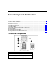
Server Component Identification In This Section Front Panel Components ................................................................................................................7 Front Panel LEDs and Buttons .......................................................................................................8 Rear Panel Components..................................................................................................................9 Rear Panel LEDs .....................................
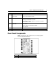
Reference and Troubleshooting Guide Item Description 4 System power button 5 UID button 6 Diskette drive 7 CD-ROM drive Front Panel LEDs and Buttons Item Description Status 1 UID LED Blue = Activated Flashing = System remotely managed Off = Deactiviated 2 Internal health LED Green = Normal Amber = System degraded. Refer to system board LEDs to identify component in degraded state. Red = System critical. Refer to system board LEDs to identify component in critical state.
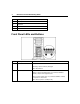
Server Component Identification Item Description Status 3 External health LED (power supply) Green = Normal NIC activity LED Green = Network link 4 Red = Power redundancy failure Flashing = Network link and activity Off = No link to network. If power is off, view the rear panel RJ-45 LEDs for status. 5 Power LED On = Power Amber = System off and power available Off = No power 6 System power button 7 UID button Rear Panel Components NOTE: Hot-plug power supply model shown.
Reference and Troubleshooting Guide Item Description 2 Optional hot-plug redundant power supply bay 3 SCSI connector knockouts 4 PCI Express 4x (half length card), slot 1 5 PCI Express 8x (full length card), slot 2 6 64-bit 100 MHz PCI-X slot, bus 9, slot 3 7 64-bit 100 MHz PCI-X slot, bus 9, slot 4 8 64-bit 133 MHz PCI-X slot, bus 6, slot 5 9 64-bit 66 MHz PCI-X slot, bus 2, slot 6 10 RJ-45 Ethernet connector 11 USB 2.
Server Component Identification Rear Panel LEDs Location LED Status 1 Power supply LED Off = No power or inadequate power supply Green = Power supply is on and functioning 2 UID LED Blue = Activated Off = Deactivated Flashing = Remote inquiry 3 10/100/1000 On = Link NIC link LED Flashing = Activity Off = No Link 4 10/100/1000 On = Standby NIC standby LED Off = Activity 11
Reference and Troubleshooting Guide System Board Components NOTE: PPM 1 is embedded onto the system board.
Server Component Identification Item Description Item Description 10 Secondary SCSI connector* 24 Serial port header 11 PPM 2 socket 25 DIMM slot 4 12 RILOE II connector (30-pin) 26 DIMM slot 3 13 System maintenance switch 27 DIMM slot 2 14 64-bit 66 MHz PCI-X slot, bus 2 28 DIMM slot 1 13 *For SCSI models only NMI Jumper The NMI jumper allows administrators to perform a memory dump before performing a hard reset.
Reference and Troubleshooting Guide Position Default Function S3 Off Reserved S4 Off Reserved S5 Off Off = Power-on password is enabled. On = Power-on password is disabled. S6 Off Off = No function On = Clear NVRAM S7 Reserved S8 Reserved When the system maintenance switch position 6 is set to the On position, the system is prepared to erase all system configuration settings from both CMOS and NVRAM. CAUTION: Clearing CMOS and/or NVRAM deletes configuration information.
Server Component Identification System Board LEDs Item LED Description Status 1 AC power Off = No AC power or failed power supply Green = Power supply is on and functioning 2 3 Processor 1 fan status Off = Processor fan is functioning Processor 1 status Off = Processor 1 functioning Amber = Fan is not installed or has failed Amber = Processor 1 failed 4 5 6 PPM 1 (embedded) status Off = PPM 1 functioning Processor 2 fan status Off = Processor fan is functioning Processor 2 status Off
Reference and Troubleshooting Guide Item LED Description Status 8 Temperature threshold Off = Normal Redundant fan status Off = Fan is functioning Rear fan status Off = Processor fan is functioning 9 10 Amber = System temperature threshold exceeded Amber = Redundant fan has failed Amber = Fan is not installed or has failed 11 DIMM 4 status Off = DIMM 4 functioning Amber = DIMM 4 failed 12 DIMM 3 status Off = DIMM 3 functioning Amber = DIMM 3 failed 13 DIMM 2 status Off = DIMM 2 fu
Server Component Identification System LED and Color Internal Health LED Color Status Processor failure, socket X (Amber) Red One or more of the following conditions may exist: • Processor in socket X has failed. • Processor in socket X failed over to the second processor. • Processor X is not installed in the socket. • Processor X is not supported. • Processor heatsink is not attached properly. Amber Processor in socket X is in a pre-failure condition.
Reference and Troubleshooting Guide Hot-Plug SCSI IDs The server supports single- or dual-channel SCSI hard drive configurations. The single-channel configuration (simplex) supports up to six SCSI hard drives on one channel. The dual-channel configuration (duplex) supports two SCSI hard drives on one channel (SCSI IDs 4 and 5) and up to four SCSI hard drives on the other channel (SCSI IDs 0 through 3) with the duplex option. The SCSI IDs for both simplex and duplex configurations are illustrated.
Server Component Identification Hot-Plug SCSI Hard Drive LEDs Item LED Description Status 1 Activity status On = Drive activity Flashing = High activity on the drive or drive is being configured as part of an array. Off = No drive activity 2 Online status On = Drive is part of an array and is currently working. Flashing = Drive is actively online. Off = Drive is offline.
Reference and Troubleshooting Guide Hot-Plug SCSI Hard Drive LED Combinations Activity LED (1) Online LED (2) Fault LED Interpretation (3) On, off, or flashing On or off Flashing On, off, or flashing On On or flashing Flashing A predictive failure alert has been received for this drive. Replace the drive as soon as possible. Off The drive is online and is configured as part of an array.
Server Operations In This Section Powering Up the Server................................................................................................................21 Powering Down the Server...........................................................................................................21 Extending the Server from the Rack.............................................................................................22 Removing Front Tower Bezel ..............................................
Reference and Troubleshooting Guide 5. If the server is installed in a rack, locate the server by identifying the illuminated rear UID LED button. 6. Disconnect the power cords. The system is now without power. Extending the Server from the Rack 1. Loosen the thumbscrews that secure the server faceplate to the front of the rack. IMPORTANT: If the server is installed in a telco rack, remove the server from the rack to access internal components. 2.
Server Operations 23 b. Secure the server by tightening the thumbscrews. Removing Front Tower Bezel This server has a removable front bezel that must be unlocked and opened before accessing the hard drive cage and removable media area, and before removing the access panel. The door should be kept closed during normal server operations. Use the key provided with the server to unlock the bezel with a counterclockwise turn. If necessary, remove the front bezel. Removing Access Panel 1.
Reference and Troubleshooting Guide NOTE: Turn the access panel over to locate the System Configuration and Options hood labels. These labels will provide information on installing various options, flexible memory configurations, LED status indicators, and switch settings. 4. To replace the access panel, reverse steps 1 through 3.
Server Setup In This Section Optional Installation Services.......................................................................................................25 Optimum Environment .................................................................................................................26 Rack Planning Resources .............................................................................................................30 Rack Warnings .........................................................
Reference and Troubleshooting Guide • • − Microsoft® − Linux − HP ProLiant Essentials (HP SIM and RDP) − VMWare Integrated hardware and software support − Critical Service − Proactive 24 − Support Plus − Support Plus 24 Startup and implementation services for both hardware and software For more information on Care Packs, refer to the HP website (http://www.hp.com/hps/carepack/servers/cp_proliant.html).
Server Setup 27 • Leave a minimum clearance of 76.2 cm (30 in) in front of the rack. • Leave a minimum clearance of 76.2 cm (30 in) behind the rack. • Leave a minimum clearance of 121.9 cm (48 in) from the back of the rack to the back of another rack or row of racks. HP servers draw in cool air through the front and expel warm air through the rear.
Reference and Troubleshooting Guide CAUTION: Always use blanking panels to fill empty vertical spaces in the rack. This arrangement ensures proper airflow. Using a rack without blanking panels results in improper cooling that can lead to thermal damage. Temperature Requirements To ensure continued safe and reliable equipment operation, install or position the system in a well-ventilated, climate-controlled environment.
Server Setup 29 CAUTION: Protect the server from power fluctuations and temporary interruptions with a regulating uninterruptible power supply (UPS). This device protects the hardware from damage caused by power surges and voltage spikes and keeps the system in operation during a power failure. When installing more than one server, you may need to use additional power distribution devices to safely provide power to all devices.
Reference and Troubleshooting Guide Rack Planning Resources The rack resource kit ships with all HP branded or Compaq branded 9000, 10000, and H9 series racks. A summary of the content of each resource follows: • Custom Builder is a web-based service for configuring one or many racks. Rack configurations can be created using: − A simple, guided interface − Build-it-yourself mode For more information, refer to the HP website (http://www.hp.com/products/configurator).
Server Setup • The leveling jacks are extended to the floor. • The full weight of the rack rests on the leveling jacks. • The stabilizing feet are attached to the rack if it is a single-rack installation. • The racks are coupled together in multiple-rack installations. • Only one component is extended at a time. A rack may become unstable if more than one component is extended for any reason.
Reference and Troubleshooting Guide • Hardware options • Operating system or application software • UPS Identifying Rack Server Shipping Carton Contents Unpack the server shipping carton and locate the materials and documentation necessary for installing the server. All the rack mounting hardware necessary for installing the server into the rack is included with the rack or the server.
Server Setup 33 Setting up a Tower Server Follow the steps in this section to set up a tower model server. If you you are going to install the server into a rack, refer to the rack installation ("Installing the Server into the Rack" on page 34) section. 1. Connect peripheral devices to the server. WARNING: To reduce the risk of electric shock, fire, or damage to the equipment, do not plug telephone or telecommunications connectors into RJ-45 connectors.
Reference and Troubleshooting Guide Item Description 6 64-bit 100 MHz PCI-X slot, bus 9, slot 3 7 64-bit 100 MHz PCI-X slot, bus 9, slot 4 8 64-bit 133 MHz PCI-X slot, bus 6, slot 5 9 64-bit 66 MHz PCI-X slot, bus, 2, slot 6 10 RJ-45 Ethernet connector 11 USB 2.0 connectors (2) 12 Video connector 13 Parallel connector 14 Serial connector 15 Keyboard connector 16 Mouse connector 2. Connect the power cord to the back of the server. 3. Connect the power cord to the AC power source.
Server Setup 35 NOTE: If using a round-hole rack, follow the same steps using the round-hole cage nuts provided with the kit. If you are installing the server into a telco rack, order the appropriate option kit at the RackSolutions.com website (http://www.racksolutions.com/hp). Follow the server-specific instructions on the website to install the rack brackets. After installing the brackets, follow the steps in this section.
Reference and Troubleshooting Guide 2. Extend the component rail until the rail-release latch engages. Press the latch and continue to pull the component rail until it is completely separate from the rack rail. 3. Secure each server component rail to the server.
Server Setup 4. Install the rack rails in the rack. 5. Press the rail-release latches, slide the server into the rack and tighten the thumbscrews. WARNING: To reduce the risk of personal injury or damage to the equipment, adequately stabilize the rack before extending a component outside the rack. Extend only one component at a time. A rack may become unstable if more than one component is extended.
Reference and Troubleshooting Guide CAUTION: Be sure to keep the server parallel to the floor when sliding the server rails into the rack rails. Tilting the server up or down could result in damage to the rails. 6. Secure the cable management bracket to the rear of the server using a T-15 Torx screwdriver.
Server Setup 7. Secure the cable management arm to the bracket. 8. Secure the cable management arm to the rack. 9. Connect peripheral devices to the server. Refer to setting up a tower server (on page 33) for more information on rear panel component connection. 10. Connect the power cord to the back of the server.
Reference and Troubleshooting Guide 11. Route cables through the cable management arm. 12. Connect the power cord to the AC power source. WARNING: To reduce the risk of electric shock or damage to the equipment: • Do not disable the power cord grounding plug. The grounding plug is an important safety feature. • Plug the power cord into a grounded (earthed) electrical outlet that is easily accessible at all times. • Unplug the power cord from the power supply to disconnect power to the equipment.
Server Setup 41 • Press the F8 key when prompted during the array controller initialization to configure the array controller using ORCA. The array controller defaults to RAID 0 with one drive installed and RAID 1 with more than one drive installed. • Press the F9 key when prompted during the boot process to change the server settings using RBSU. The system is set up by default for the English language.
Hardware Options Installation In This Section Introduction ..................................................................................................................................43 Processor Option ..........................................................................................................................44 Memory Options...........................................................................................................................48 Hard Drive Options ...............
Reference and Troubleshooting Guide Processor Option The server supports single- and dual-processor operation. With two processors installed, the server supports boot functions through the processor installed in processor socket 1. However, if processor 1 fails, the system automatically boots from processor 2 and provides a processor failure message. The server uses PPMs as DC-to-DC converters to provide the proper power to each processor. Processor 1 uses an embedded PPM.
Hardware Options Installation 6. Install the processor and close the processor locking lever. CAUTION: Forcing the processor locking lever could lead to hardware damage.
Reference and Troubleshooting Guide 7. Install the heatsink. 8. Close the processor retaining brackets.
Hardware Options Installation 9. Connect the heatsink connector to the header on the system board. Item Description 1 CPU 1 heatsink header 2 CPU 2 heatsink header 10. Open the latches on the corresponding PPM slot. 11. Install the PPM for processor 2 (if installing a second processor). NOTE: PPM 1 is embedded onto the system board.
Reference and Troubleshooting Guide NOTE: The appearance of compatible PPMs may vary. 12. Replace the front bezel ("Removing Front Tower Bezel" on page 23), if applicable. 13. Replace the access panel ("Removing Access Panel" on page 23). Memory Options You can expand server memory by installing PC2700 DDR SDRAM DIMMs. The system supports up to four ECC Registered DDR SDRAM DIMMs.
Hardware Options Installation 49 5. Open the DIMM slot latches. 6. Install the DIMM. 7. Replace the front bezel ("Removing Front Tower Bezel" on page 23), if applicable. 8. Replace the access panel ("Removing Access Panel" on page 23). Interleaving and Non-Interleaving Memory Configuration This server supports both interleaving and non-interleaving memory configurations.
Reference and Troubleshooting Guide Activating Interleaving Memory Interleaving memory functionality is automatically activated whenever two identical DIMMs are detected in sockets 1 and 2. If sockets 3 and 4 are populated, it must be with identical DIMMs as well. If identical DIMMs are installed in sockets 1, 2, and 3, the system will not boot. For more information, refer to "Server Software and Configuration Utilities (on page 89)" in this guide.
Hardware Options Installation 51 NOTE: Depending on model purchased, the server may look slightly different than shown. SCSI Hard Drive Guidelines When adding SCSI hard drives to the server, observe the following general guidelines: • A maximum of six SCSI devices per channel can be added. • Each SCSI drive must have a unique ID. The system automatically sets all SCSI IDs on hot-plug models.
Reference and Troubleshooting Guide 2. Install the hard drive. NOTE: Depending on model purchased, the server may look slightly different than shown. 3. Determine the status of the hard drive from the hot-plug SCSI hard drive LEDs (on page 19). 4. Resume normal server operations. Installing a Non-Hot-Plug SCSI Hard Drive 1. Power down the server ("Powering Down the Server" on page 21). 2. Extend the server from the rack, if applicable ("Extending the Server from the Rack" on page 22). 3.
Hardware Options Installation 5. Use a T-15 Torx screwdriver to remove the screws from the side of the chassis and remove the bezel blank. IMPORTANT: Each SCSI device in the server must have a unique address. The server automatically sets all SCSI IDs for hot-plug drives, but you must set the SCSI IDs for devices installed in the media cage. 6. Set the SCSI ID for the non-hot-plug SCSI hard drive. Refer to the documentation that ships with the hard drive. 7.
Reference and Troubleshooting Guide 8. Insert the hard drive into the drive bay and secure with screws. 9. Connect the power cable to the hard drive. 10. Connect the four-device SCSI cable to the hard drive. 11. Slide the hard drive fully into the bay until it is seated securely. 12. Replace the front bezel ("Removing Front Tower Bezel" on page 23), if applicable. 13. Replace the access panel ("Removing Access Panel" on page 23).
Hardware Options Installation 55 Removable Media Device Options Identifying Guide Screws (on page 55) Removing the Removable Media Device Blanks Installing Half-Height or Full-Height Media Devices Installing a Tape Drive ("Installing a Tape Drive Option" on page 60) Internal Two-Bay Hot-Plug SCSI Drive Cage ("Installing the Internal Two-Bay Hot-Plug SCSI Drive Cage Option" on page 61) Identifying Guide Screws When installing drives in the removable media bay, guide screws must be installed to make sure t
Reference and Troubleshooting Guide Accessing the Removable Media Cage The server supports installation of optional internal storage devices. IMPORTANT: HP and Compaq branded SCSI non-hot-plug cables are terminated. Remove all terminating jumpers from third-party SCSI devices before installing them in the server. 1. Power down the server ("Powering Down the Server" on page 21). 2. Extend the server from the rack, if applicable ("Extending the Server from the Rack" on page 22). 3.
Hardware Options Installation 57 8. Replace the front bezel ("Removing Front Tower Bezel" on page 23), if applicable. 9. Replace the access panel ("Removing Access Panel" on page 23). Removing Shipping Brackets Shipping brackets prevent the drive cage from moving while the server is being shipped. NOTE: The shipping brackets do not need to be removed from the server when the server is in normal operation. Before installing an option into the removable media bay area, remove the shipping brackets.
Reference and Troubleshooting Guide Installing a Half-Height or Full-Height Media Device Option The server includes four removable media bays. The lower two bays are occupied with a 3.5-inch diskette drive and an IDE CD-ROM drive. The upper two removable media bays are vacant. You can install up to two half-height or one full-height removable media devices in the removable media cage. To install a half-height or full-height media device: 1. Power down the server ("Powering Down the Server" on page 21).
Hardware Options Installation 9. Slide the drive into the bay until it clicks into place. 10. Connect the data and power cables to the back of the device. 11. Connect the data cable into a SCSI controller channel (secondary SCSI channel shown). 12. Replace the front bezel ("Removing Front Tower Bezel" on page 23), if applicable. 13. Replace the access panel ("Removing Access Panel" on page 23).
Reference and Troubleshooting Guide Installing a Tape Drive Option 1. Power down the server ("Powering Down the Server" on page 21). 2. Extend the server from the rack, if applicable ("Extending the Server from the Rack" on page 22). 3. Remove the front bezel door, if necessary ("Removing Front Tower Bezel" on page 23). 4. Remove the access panel ("Removing Access Panel" on page 23). 5. Install the guide screws ("Identifying Guide Screws" on page 55), if applicable. 6.
Hardware Options Installation 61 8. Connect the data and power cables to the back of the device. 9. Connect the data cable into a SCSI controller channel (secondary SCSI channel shown). 10. Replace the front bezel ("Removing Front Tower Bezel" on page 23), if applicable. 11. Replace the access panel ("Removing Access Panel" on page 23).
Reference and Troubleshooting Guide 5. Using the T-15 Torx screwdriver attached to the back of the server, position two screws in the upper mounting holes on each side of the drive cage. 6. Slide the drive cage into the chassis until it locks into place. IMPORTANT: Be sure that the unit identification numbers (0 and 1) appear on the right side of the drive cage front panel.
Hardware Options Installation 7. Connect the SCSI and power cables. 8. Replace the front bezel ("Removing Front Tower Bezel" on page 23), if applicable. 9. Replace the access panel ("Removing Access Panel" on page 23). Refer to the HP Internal Two-Bay Hot-Plug SCSI Drive Cage Installation Instructions for additional information.
Reference and Troubleshooting Guide WARNING: To reduce the risk of injury from electric shock hazards, do not open power supplies. Refer all maintenance, upgrades, and servicing to qualified personnel. CAUTION: Electrostatic discharge (ESD) can damage electronic components. Be sure that you are properly grounded (earthed) before beginning any installation procedure. NOTE: Do not attempt to remove the power supply from a non-hot-plug SCSI model.
Hardware Options Installation 65 3. Slide the power supply into the power supply bay, then apply pressure to the power supply until the release/lock lever clicks the power supply securely into the bay. 4. Connect the power cords to the power supplies. 5. Be sure that the power supply and redundant power supply LEDs ("Rear Panel LEDs" on page 11) are green. Expansion Board Options The server supports PCI, PCI-X, and PCI Express expansion boards.
Reference and Troubleshooting Guide CAUTION: To prevent improper cooling and thermal damage, do not operate the server unless all PCI slots have either an expansion slot cover or an expansion board installed. To replace the component, reverse the removal procedure. Installing an Expansion Board CAUTION: To prevent damage to the server or expansion boards, power down the server and remove all AC power cords before removing or installing the expansion boards. To install an expansion board: 1.
Hardware Options Installation IMPORTANT: It may be necessary to remove the slot cover next to the slot in which you are installing a board. 6. Loosen the thumbscrews on the expansion board retainer and pull the retainer out away from the chassis. 7. Install the expansion board. IMPORTANT: Be sure to insert expansion boards into the appropriate type of expansion slot.
Reference and Troubleshooting Guide 9. Connect any required internal or external cables to the expansion board. Refer to the documentation that ships with the expansion board. 10. Reinstall the expansion board retainer, then tighten the thumbscrew. 11. Replace the front bezel ("Removing Front Tower Bezel" on page 23), if applicable. 12. Replace the access panel ("Removing Access Panel" on page 23).
Hardware Options Installation 5. Using a T-15 Torx screwdriver, remove the screw holding the SCSI knockout cover plate located on the rear of the chassis and remove it from the chassis. 6. Insert the SCSI connector into the open area. Secure the external SCSI connector to the chassis using the screws provided with the external SCSI connector option kit.
Reference and Troubleshooting Guide 7. Secure the internal-to-external SCSI connector cable to either internal SCSI channel (primary or secondary) or to the SCSI channel of an option card. NOTE: Refer to the documentation that shipped with the external storage device for more information. 8. Replace the front bezel ("Removing Front Tower Bezel" on page 23), if applicable. 9. Replace the access panel ("Removing Access Panel" on page 23).
Hardware Options Installation 71 Tower-to-Rack Conversion Option Converting a Tower Server to a Rack Server (on page 71) Installing the Rack Server (on page 74) Accessing the Server in the Rack (on page 74) Converting a Tower Server to a Rack Server The tower-to-rack conversion kit includes all equipment required to convert the tower model server into a rack model server, and to install the server into most square- or round-hole racks.
Reference and Troubleshooting Guide 4. Remove the access panel ("Removing Access Panel" on page 23). 5. Disengage the locking brackets and pull them out. 6.
Hardware Options Installation 73 a. Use the T-10 Torx screwdriver to remove the two front panel screws. Slide tower configuration panel back and then away from the chassis. 7. Align the pins on the server bezel with the corresponding slots on the chassis and push down. Secure the server bezel to the chassis by tightening the thumbscrews. 8. Replace the access panel ("Removing Access Panel" on page 23).
Reference and Troubleshooting Guide Installing the Rack Server To install the rack server: 1. Install the server into a rack ("Installing the Server into the Rack" on page 34). 2. Connect the power cord and peripheral devices. Refer to Rear Panel Components (on page 9) for connector locations. 3. Power up the server ("Powering Up the Server" on page 21). 4. Install the operating system ("Installing the Operating System" on page 41). 5. Register the server.
Hardware Options Installation 75 2. Reverse step 1 to secure the cable management arm after the maintenance procedures have been completed. Installing a Second Serial Port To install the second serial port option: 1. Power down the server ("Powering Down the Server" on page 21). 2. Extend the server from the rack, if applicable ("Extending the Server from the Rack" on page 22). 3. Remove the front bezel door, if necessary ("Removing Front Tower Bezel" on page 23). 4.
Reference and Troubleshooting Guide Installing a Redundant Fan To install a redundant fan: 1. Power down the server ("Powering Down the Server" on page 21). 2. Extend the server from the rack, if applicable ("Extending the Server from the Rack" on page 22). 3. Remove the front bezel door, if necessary ("Removing Front Tower Bezel" on page 23). 4. Remove the access panel ("Removing Access Panel" on page 23). 5. Install the redundant fan assembly and tighten the thumbscrew.
Server Cabling In This Section Cabling Guidelines .......................................................................................................................77 SCSI Hot-Plug Cabling ................................................................................................................77 Non-Hot-Plug SCSI Cabling ........................................................................................................88 Connecting ATA or ATAPI Devices to the Integrated IDE Controller..
Reference and Troubleshooting Guide • As a general rule, a maximum of six devices may be added per channel. The server is equipped with two integrated Ultra320 SCSI channels. • The configuration settings on each SCSI device should be set to the SCSI ID of the bay (Bay 0 = SCSI ID 0) that it will occupy. • If only one SCSI hard drive is used, it should be installed in the lowestnumbered bay (0). • Be sure to remove all terminating jumpers from third-party SCSI devices.
Server Cabling 79 Hot-Plug Hard Drive SCSI Cable The SCSI cable shown is included with the server. The SCSI cable connects the hot-plug drive cage to the SCSI controller. The hot-plug hard drive cage has built-in termination. Simplex Hot-Plug SCSI Cabling In the simplex cabling configuration, an optional PCI array controller or embedded primary SCSI controller controls up to six hard drives through one SCSI bus. CAUTION: Secondary SCSI controller is not recommended in simplex mode.
Reference and Troubleshooting Guide NOTE: The server ships with the required cables. Item Component description SCSI IDs managed 1 SCSI cable 0, 1, 2, 3, 4, 5 2 SCSI cable used to jumper the two SCSI buses together N/A IMPORTANT: After changing any SCSI configuration, be sure the proper boot controller order is set in RBSU.
Server Cabling Duplex Hot-Plug SCSI Cabling In the duplex cabling configuration, refer to the documentation that ships with this option. Item Description SCSI IDs Connection 1 SCSI cable 4,5 Secondary SCSI channel or Smart Array controller 2 Duplex SCSI cable (optional) 0,1,2,3 Primary SCSI channel or Smart Array controller IMPORTANT: After changing any SCSI configuration, be sure the proper boot controller order is set in RBSU.
Reference and Troubleshooting Guide Array Controller Duplex SCSI Cabling In the array controller duplex SCSI cabling configuration, the optional PCI array controller controls up to four hard drives on one SCSI channel and two hard drives on the other SCSI channel. Item Component description SCSI IDs managed 1 SCSI cable 4, 5 2 SCSI cable * 0, 1, 2, 3 * One SCSI cable is provided with the server, and one SCSI cable is provided with the Duplex SCSI Backplane Option Kit.
Server Cabling Internal SCSI Components Before cabling the server, note the removable media and hard drive cage locations. For additional information about installing SCSI devices, refer to the documentation included with the device.
Reference and Troubleshooting Guide Media Bays and Hard Drives Number Description 1 Removable media bay 2 Hot-plug SCSI hard drive cage 3 Non-hot-plug SCSI hard drive cage 68-to-50 Pin SCSI Adapter If installing a device that uses a Fast SCSI-2 interface, you must provide a 68-to50 pin SCSI adapter. This adapter should be installed between the 50-pin interface on the device and the 68-pin SCSI cable connected to the SCSI channel on the system board.
Server Cabling 85 Installing an Internal-to-External SCSI Connector If you are not using one or both SCSI channels (primary or secondary) internally or you install a SCSI or SmartArray option card, you may install an internal-toexternal SCSI connector in the SCSI knockout locations on the rear of the chassis. For installation instructions, refer to the VHDCI or HD68 SCSI Cable ("VHDCI or HD68 SCSI Cable Option" on page 68) section in this guide.
Reference and Troubleshooting Guide 1. Locate and remove the SCSI cable from the SCSI primary connector on the system board. 2. Reconnect the SCSI cable to either the SCSI controller option or SmartArray Controller. NOTE: Both SCSI channels are self-terminating. If you choose to not use one or both of the SCSI channels, you do not need to terminate the unused channel(s).
Server Cabling 87 Cabling SCSI Devices in the Removable Media Area The following steps detail the procedure for cabling an integrated SCSI controller to a removable media or other device: 1. Install removable media device ("Installing a Half-Height or Full-Height Media Device Option" on page 58). Be sure that the SCSI ID is uniquely set on each device. 2. Locate the SCSI cable that is shipped with the option. For more information on cables, refer to the HP website (http://www.hp.
Reference and Troubleshooting Guide Non-Hot-Plug SCSI Cabling Refer to non-hot-plug SCSI hard drive installation ("Installing a Non-Hot-Plug SCSI Hard Drive" on page 52) for more information. Connecting ATA or ATAPI Devices to the Integrated IDE Controller This server includes one IDE cable (the Cable Select Cable) that can connect up to two ATA or ATAPI devices to the system through the integrated IDE controller. This cable has three clearly labeled connectors.
Server Software and Configuration Utilities In This Section Configuration Tools......................................................................................................................89 Management Tools .......................................................................................................................95 Diagnostic Tools.........................................................................................................................100 Keeping the System Current..
Reference and Troubleshooting Guide • Installing optimized server drivers, management agents and utilities automatically with every assisted installation • Testing server hardware using the Insight Diagnostics Utility ("HP Insight Diagnostics" on page 101) • Installing software drivers directly from the CD. With systems that have internet connection, the SmartStart Autorun Menu provides access to a complete list of ProLiant system software.
Server Software and Configuration Utilities 91 ROM-Based Setup Utility RBSU, an embedded configuration utility, performs a wide range of configuration activities that may include: • Configuring system devices and installed options • Displaying system information • Selecting the primary boot controller For more information on RBSU, refer to the HP ROM-Based Setup Utility User Guide on the Documentation CD or the HP website (ftp://ftp.compaq.com/pub/products/servers/management/rbsu-whitepaper.pdf).
Reference and Troubleshooting Guide NOTE: The server may not support all the following examples. NOTE: If the boot drive is not empty or has been written to in the past, ORCA does not automatically configure the array. You must run ORCA to configure the array settings.
Server Software and Configuration Utilities 93 BIOS Serial Console BIOS Serial Console allows you to configure the serial port to view POST error messages and run RBSU remotely through a serial connection to the server COM port. The server that you are remotely configuring does not require a keyboard and mouse. For more information about BIOS Serial Console, refer to the BIOS Serial Console User Guide on the Documentation CD or the HP website (http://www.compaq.com/support/techpubs/whitepapers).
Reference and Troubleshooting Guide Option ROM Configuration for Arrays Before installing an operating system, you can use the ORCA utility to create the first logical drive, assign RAID levels, and establish online spare configurations.
Server Software and Configuration Utilities 95 1. During the server startup sequence, press the F9 key to access RBSU. 2. Select the System Options menu. 3. Select Serial Number. The following warning is displayed: WARNING! WARNING! WARNING! The serial number is loaded into the system during the manufacturing process and should NOT be modified. This option should only be used by qualified service personnel. This value should always match the serial number sticker located on the chassis. 4.
Reference and Troubleshooting Guide Automatic Server Recovery ASR is a feature that causes the system to restart when a catastrophic operating system error occurs, such as a blue screen, ABEND, or panic. A system fail-safe timer, the ASR timer, starts when the System Management driver, also known as the Health Driver, is loaded. When the operating system is functioning properly, the system periodically resets the timer.
Server Software and Configuration Utilities 97 IMPORTANT: This utility supports operating systems that may not be supported by the server. For operating systems supported by the server, refer to the HP website (http://www.hp.com/go/supportos).
Reference and Troubleshooting Guide Management Agents Management Agents provide the information to enable fault, performance, and configuration management. The agents allow easy manageability of the server through HP Systems Insight Manager software, and third-party SNMP management platforms. Management Agents are installed with every SmartStart assisted installation or can be installed through the HP PSP.
Server Software and Configuration Utilities 99 Safety and Security Benefits When you flash the system ROM, ROMPaq writes over the backup ROM and saves the current ROM as a backup, enabling you to switch easily to the alternate ROM version if the new ROM becomes corrupted for any reason. This feature protects the existing ROM version, even if you experience a power failure while flashing the ROM. Access to Redundant ROM Settings To access the redundant ROM through RBSU: 1.
Reference and Troubleshooting Guide When the server boots, the system identifies whether the current ROM bank is corrupt. If a corrupt ROM is detected, the system boots from the backup ROM and alerts you through POST or IML that the ROM bank is corrupt. If both the current and backup versions of the ROM are corrupt, the server automatically enters ROMPaq disaster recovery mode. USB Support HP provides both standard USB support and legacy USB support.
Server Software and Configuration Utilities 101 Array Diagnostic Utility ADU is a Windows-based tool that collects information about array controllers and generates a list of detected problems. For a list of error messages, refer to "ADU Error Messages (on page 171)." ADU can be accessed from the SmartStart CD ("SmartStart Software" on page 89).
Reference and Troubleshooting Guide Keeping the System Current List of Tools: Drivers ........................................................................................................................................102 ProLiant Support Packs ..............................................................................................................102 Operating System Version Support ............................................................................................
Server Software and Configuration Utilities 103 Operating System Version Support Refer to the operating system support matrix (http://www.hp.com/go/supportos). Change Control and Proactive Notification HP offers Change Control and Proactive Notification to notify customers 30 to 60 days in advance of upcoming hardware and software changes on HP commercial products. For more information, refer to the HP website (http://h18023.www1.hp.com/solutions/pcsolutions/pcn.html).
Troubleshooting In This Section Server Diagnostic Steps..............................................................................................................105 Procedures for All ProLiant Servers...........................................................................................126 Error Messages ...........................................................................................................................
Reference and Troubleshooting Guide Important Safety Information Before servicing this product, read the Important Safety Information document provided with the server. Symbols on Equipment The following symbols may be placed on equipment to indicate the presence of potentially hazardous conditions. This symbol indicates the presence of hazardous energy circuits or electric shock hazards. Refer all servicing to qualified personnel.
Troubleshooting 27.22 kg 60 lb This symbol indicates that the component exceeds the recommended weight for one individual to handle safely. WARNING: To reduce the risk of personal injury or damage to the equipment, observe local occupational health and safety requirements and guidelines for manual material handling. These symbols, on power supplies or systems, indicate that the equipment is supplied by multiple sources of power.
Reference and Troubleshooting Guide • The leveling jacks are extended to the floor. • The full weight of the rack rests on the leveling jacks. • The stabilizing feet are attached to the rack if it is a single-rack installation. • The racks are coupled together in multiple-rack installations. • Only one component is extended at a time. A rack may become unstable if more than one component is extended for any reason.
Troubleshooting • Observe local occupation health and safety requirements and guidelines for manual handling. • Obtain adequate assistance to lift and stabilize the chassis during installation or removal. • The server is unstable when not fastened to the rails. • When mounting the server in a rack, remove the power supplies and any other removable module to reduce the overall weight of the product. 109 CAUTION: To properly ventilate the system, you must provide at least 7.6 cm (3.
Reference and Troubleshooting Guide 6. Collect all tools and utilities, such as a Torx screwdriver, loopback adapters, ESD wrist strap, and software utilities, necessary to troubleshoot the problem. − You must have the appropriate Health Drivers and Management Agents installed on the server. NOTE: To verify the server configuration, connect to the System Management homepage and select Version Control Agent.
Troubleshooting 111 Diagnostic Steps To effectively troubleshoot a problem, HP recommends that you start with the first flowchart in this section, "Start Diagnosis Flowchart (on page 111)," and follow the appropriate diagnostic path. If the other flowcharts do not provide a troubleshooting solution, follow the diagnostic steps in "General Diagnosis Flowchart (on page 113).
Reference and Troubleshooting Guide
Troubleshooting 113 General Diagnosis Flowchart The General Diagnosis flowchart provides a generic approach to troubleshooting. If you are unsure of the problem, or if the other flowcharts do not fix the problem, use the following flowchart. Item Refer to 1 "Symptom Information" 2 "Loose Connections (on page 129)" 3 "Service Notifications" 4 Server maintenance and service guide, located on the Documentation CD or the HP website (http://www.hp.
Reference and Troubleshooting Guide
Troubleshooting Power-On Problems Flowchart Symptoms: • The server does not power on. • The system power LED is off or amber. • The external health LED is red or amber. • The internal health LED is red or amber. NOTE: For the location of server LEDs and information on their statuses, refer to the server documentation.
Reference and Troubleshooting Guide Item Refer to 7 • "Power Supply Problems (on page 127)" • Server maintenance and service guide, located on the Documentation CD or the HP website (http://www.hp.
Troubleshooting 117
Reference and Troubleshooting Guide POST Problems Flowchart Symptoms: • Server does not complete POST NOTE: The server has completed POST when the system attempts to access the boot device.
Troubleshooting 119
Reference and Troubleshooting Guide OS Boot Problems Flowchart Symptoms: • Server does not boot a previously installed operating system • Server does not boot SmartStart Possible Causes: • Corrupted operating system • Hard drive subsystem problem Item Refer to 1 HP ROM-Based Setup Utility User Guide (http://www.hp.
Reference and Troubleshooting Guide
Troubleshooting 123 Server Fault Indications Flowchart Symptoms: • Server boots, but a fault event is reported by Insight Management Agents (on page 98) • Server boots, but the internal health LED or external health LED is red or amber NOTE: For the location of server LEDs and information on their statuses, refer to the server documentation.
Reference and Troubleshooting Guide Item Refer to 8 • "Hardware Problems (on page 126)" • Server maintenance and service guide, located on the Documentation CD or the HP website (http://www.hp.
Troubleshooting 125
Reference and Troubleshooting Guide Procedures for All ProLiant Servers The procedures in this section are comprehensive and include steps about or references to hardware features that may not be supported by the server you are troubleshooting. Hardware Problems Power Problems (on page 126) General Hardware Problems (on page 128) Internal System Problems (on page 132) External Device Problems (on page 146) Power Problems List of Problems: Power Source Problems.........................................
Troubleshooting 127 5. Have a qualified electrician check the line voltage to be sure it meets the required specifications. 6. Be sure the proper circuit breaker is in the On position. Power Supply Problems Action: 1. Be sure no loose connections (on page 129) exist. 2. If the power supplies have LEDs, be sure they indicate that each power supply is working properly. Refer to the server documentation. If LEDs indicate a problem with a power supply, replace the power supply. 3.
Reference and Troubleshooting Guide 6. Be sure each circuit breaker is in the On position, or replace the fuse if needed. If this occurs repeatedly, contact an authorized service provider. 7. Check the UPS LEDs to be sure a battery or site wiring problem has not occurred. Refer to the UPS documentation. 8. If the UPS sleep mode initiated, disable sleep mode for proper operation. The UPS sleep mode can be turned off through the configuration mode on the front panel. 9.
Troubleshooting 129 Loose Connections Action: • Be sure all power cords are securely connected. • Be sure all cables are properly aligned and securely connected for all external and internal components. • Remove and check all data and power cables for damage. Be sure no cables have bent pins or damaged connectors. • If a fixed cable tray is available for the server, be sure the cords and cables connected to the server are correctly routed through the tray.
Reference and Troubleshooting Guide − Installation of a SCSI device without termination or without proper ID settings − Setting of an IDE device to Master/Slave when the other device is set to Cable Select − Connection of the data cable, but not the power cable, of a new device 4. Be sure no memory, I/O, or interrupt conflicts exist. 5. Be sure no loose connections (on page 129) exist. 6. Be sure all cables are connected to the correct locations and are the correct lengths.
Troubleshooting 131 Unknown Problem Action: 1. Disconnect power to the server. 2. Following the guidelines and cautionary information in the server documentation, strip the server to its most basic configuration by removing every card or device that is not necessary to start the server. Keep the monitor connected to view the server startup process. 3. Reconnect power, and then power the system on. − If the video does not work, refer to "Video Problems (on page 146).
Reference and Troubleshooting Guide Testing the Device Action: 1. Uninstall the device. If the server works with the device removed and uninstalled, either a problem exists with the device, the server does not support the device, or a conflict exists with another device. 2. If the device is the only device on a bus, be sure the bus works by installing a different device on the bus. 3. Restarting the server each time to determine if the device is working, move the device: a.
Troubleshooting 133 Diskette Drive Problems.............................................................................................................135 DLT Drive Problems ..................................................................................................................137 Fan Problems ..............................................................................................................................139 Hard Drive Problems ......................................................
Reference and Troubleshooting Guide 2. If a paper or plastic label has been applied to the surface of the CD or DVD in use, remove the label and any adhesive residue. 3. Be sure the inserted CD or DVD format is valid for the drive. For example, be sure you are not inserting a DVD into a drive that only supports CDs. Drive is not detected Action: 1. Be sure no loose connections (on page 129) exist. 2. Refer to the drive documentation to be sure cables are connected as required. 3.
Troubleshooting 135 DAT drives require cleaning every 8 to 25 hours of use or they may fail intermittently when using marginal or bad media. Be sure you are following the proper cleaning procedures described in the device and server documentation. NOTE: New DAT tapes may contain debris that will contaminate the DAT drive read/write head. If using new tapes for backup, clean the DAT drive frequently.
Reference and Troubleshooting Guide 3. Be sure the diskette is properly inserted. Remove the diskette and reinsert correctly into the drive. 4. Be sure the diskette drive is cabled properly. Refer to the server documentation. A problem has occurred with a diskette transaction Action: Be sure the directory structure on the diskette is not bad. Run the diskette utility to check for fragmentation (CHKDSK on some systems). Diskette drive cannot read a diskette Action: 1.
Troubleshooting 137 DLT Drive Problems List of Problems: Server cannot write to tape .........................................................................................................137 DLT drive failure occurs ............................................................................................................138 DLT drive does not read tape .....................................................................................................138 Server cannot find the DLT drive.............
Reference and Troubleshooting Guide DLT drive failure occurs Action: • Be sure the power and signal cables are properly connected. • Be sure the power and signal cable connectors are not damaged. • If the drive is connected to a nonembedded controller, be sure the controller is properly seated. DLT drive does not read tape Action: • Be sure the drive is seated. • Be sure the drive is installed properly.
Troubleshooting 139 DLT drives can be daisy chained, but do not connect more than three units per SCSI controller. The last DLT drive in the chain requires the SCSI terminator. • Check cables for damaged or bent connectors. An error occurs during backup, but the backup is completed Action: Contact the software vendor for more information about the message. If the error does not disrupt the backup, you may be able to ignore the error. Fan Problems List of Problems: General fan problems are occurring ...
Reference and Troubleshooting Guide 6. Replace any required non-functioning fans and restart the server. Refer to the server documentation for specifications on fan requirements. 7. Be sure all fan slots have fans or blanks installed. Refer to the server documentation for requirements. 8. Verify the fan airflow path is not blocked by cables or other material. Hard Drive Problems List of Problems: System completes POST but hard drive fails ...............................................................
Troubleshooting 141 3. Remove the hard drive and be sure the configuration jumpers are set properly. 4. If using an array controller, be sure the hard drive is configured in an array. Run the array configuration utility. 5. Be sure the drive is properly configured. Refer to the drive documentation to determine the proper configuration. 6. If it is a non-hot-plug drive, be sure a conflict does not exist with another hard drive. Check for SCSI ID conflicts. 7.
Reference and Troubleshooting Guide 3. Run Insight Diagnostics ("HP Insight Diagnostics" on page 101) and replace failed components as indicated. Memory Problems List of Problems: General memory problems are occurring ...................................................................................142 Server is out of memory .............................................................................................................142 Memory count error exists.......................................
Troubleshooting 143 Memory count error exists Possible Cause: The memory modules are not installed correctly. Action: 1. Be sure the memory modules are supported by the server. Refer to the server documentation. 2. Be sure the memory modules have been installed correctly in the right configuration. Refer to the server documentation. 3. Be sure the memory modules are properly seated. 4. Be sure no operating system errors are indicated. 5.
Reference and Troubleshooting Guide 4. Be sure the memory is properly seated. 5. Be sure no conflicts are occurring with existing memory. Run the server setup utility. 6. Test the memory by installing the memory into a known working server. Be sure the memory meets the requirements of the new server on which you are testing the memory. 7. Replace the memory. Refer to the server documentation.
Troubleshooting 145 CAUTION: Removal of some processors and heatsinks require special considerations for replacement, while other processors and heatsinks are integrated and cannot be reused once separated. For specific instructions for the server you are troubleshooting, refer to processor information in the Hardware Options Installation (on page 43) section on the Documentation CD. 5. If the server has only one processor installed, replace it with a known functional processor.
Reference and Troubleshooting Guide 4. Be sure each component in the area is working. Refer to the section for each component in this guide. If you cannot determine the problem by checking the specific area, perform each of the following actions. Restart the server after each action to see if the problem has been corrected. • Reseat all I/O expansion boards. • Be sure no loose connections (on page 129) exist in the rest of the server, particularly with the cables that connect to the system board.
Troubleshooting 147 2. Be sure the monitor power cord is plugged into a working grounded (earthed) AC outlet. 3. Be sure the monitor is cabled to the intended server or KVM connection. 4. Be sure no loose connections (on page 129) exist. − For rack-mounted servers, check the cables to the KVM switch and be sure the switch is correctly set for the server. You may need to connect the monitor directly to the server to be sure the KVM switch has not failed.
Reference and Troubleshooting Guide Monitor does not function properly with energy saver features Action: Be sure the monitor supports energy saver features, and if it does not, disable the features. Video colors are wrong Action: • Be sure the 15-pin VGA cable is securely connected to the correct VGA port on the server and to the monitor. • Be sure the monitor and any KVM switch are compatible with the VGA output of the server.
Troubleshooting 149 Printer output is garbled Action: Be sure the correct printer drivers are installed. Mouse and Keyboard Problems Action: 1. Be sure no loose connections (on page 129) exist. If a KVM switching device is in use, be sure the server is properly connected to the switch. − For rack-mounted servers, check the cables to the switch box and be sure the switch is correctly set for the server. − For tower-model servers, check the cable connection from the input device to the server. 2.
Reference and Troubleshooting Guide Action: If the Diagnostic Adapter does not have hot-plug functionality, be sure you are not using a PS/2 keyboard or mouse. With a PS/2 keyboard or mouse, the Diagnostic Adapter cannot be connected as a hot-plug device. Connect the Diagnostic Adapter before booting the server, or switch to USB devices (if supported) to use the Diagnostic Adapter hot-plug functionality. Modem Problems List of Problems: No dial tone exists .............................................
Troubleshooting 151 4. Be sure the modem on the other end is working. No response occurs when you type AT commands Action: Reconfigure the COM port address for the modem. 1. Be sure the communications software is set to the COM port to which the modem is connected. 2. Check IRQ settings in the software and on the modem to be sure no conflict exists. 3. Type AT&F at the command prompt to reset the modem to factory-default settings. 4. Be sure you are in terminal mode and not MS-DOS mode. 5.
Reference and Troubleshooting Guide 2. Be sure an answering machine is not answering the line before the modem is able to answer. a. Turn off the answering machine. -OrReconfigure the auto-answer option to respond in fewer rings than the answering machine. b. Restart the server, and then reattempt the connection. Modem disconnects while online Action: 1. Be sure no loose connections (on page 129) exist. 2. Be sure no line interference exists. Retry the connection by dialing the number several times.
Troubleshooting 153 You are unable to connect to an online subscription service Action: 1. If the line you are accessing requires error control to be turned off, do so using the AT command AT&Q6%C0. 2. If the ISP you are accessing requires access at a decreased baud rate, reconfigure the communications software to correct the connection baud rate to match the ISP. 3. If this does not work, force a slower baud rate (14400 baud) with the AT command AT&Q6N0S37=11.
Reference and Troubleshooting Guide 3. Be sure the network cable is working by replacing it with a known functional cable. 4. Be sure a software problem has not caused failure. Refer to the operating system documentation for guidelines on adding or replacing PCI Hot Plug devices, if applicable. 5. Be sure the server and operating system support the controller. Refer to the server and operating system documentation. 6. Be sure the controller is enabled in RBSU. 7.
Troubleshooting 155 Network controller stopped working when an expansion board was added Action: 1. Be sure no loose connections (on page 129) exist. 2. Be sure the server and operating system support the controller. Refer to the server and operating system documentation. 3. Be sure the new expansion board has not changed the server configuration, requiring reinstallation of the network driver. a. Uninstall the network controller driver for the malfunctioning controller in the operating system. b.
Reference and Troubleshooting Guide IMPORTANT: This guide provides information for multiple servers. Some information may not apply to the server you are troubleshooting. Refer to the server documentation for information on procedures, hardware options, software tools, and operating systems supported by the server. Refer to "Software and Option Resources" for more information.
Troubleshooting 157 Problems occur after the installation of a service pack Action: Follow the instructions for updating the operating system ("Operating System Updates" on page 157). You are unable to bind NICs during the Protocols Interview with a Factory-Installed Novell NetWare 5 operating system Action: Be sure the packet receive buffers are set high enough. Toggle over to the console during the Protocols Interview and adjust these values to a higher setting that allows you to bind the NICs.
Reference and Troubleshooting Guide 3. Install the current drivers. If you apply the update and have problems, refer to the Software and Drivers Download website (http://h18007.www1.hp.com/support/files/server) to find files to correct the problems. Restoring to a Backed-Up Version If you recently upgraded the operating system or software and cannot resolve the problem, you can try restoring a previously saved version of the system. Before restoring the backup, make a backup of the current system.
Troubleshooting 159 6. Check the operating system and application software resources to be sure you have the latest information. 7. If the last-known functioning configuration does not work, try to recover the system with operating system recovery software: − Microsoft® operating systems: Windows® 2003—Automated System Recovery Diskette. If the operating system was factory-installed, click Start>All Programs>Accessories>System Tools to access the backup utility.
Reference and Troubleshooting Guide Errors occur after an application is installed ..............................................................................160 Software locks up Action: 1. Check the application log and operating system log for entries indicating why the software failed. 2. Check for incompatibility with other software on the server. 3. Check the support website of the software vendor for known problems. 4.
Troubleshooting • Reinstall the application. • Be sure you have the most current drivers. 161 Clustering Software If the server uses cluster software, such as Microsoft® Cluster Server or Novell Cluster Services, refer to the documentation provided with the application for cluster troubleshooting information. Check the Microsoft or Novell website for software troubleshooting information and frequently asked questions.
Reference and Troubleshooting Guide • Microsoft® operating systems—PSPs are available for servers running Windows® Server 2003. SSDs are also available for other versions of Microsoft® Windows® operating systems. • Novell NetWare—PSPs are available for servers running the latest versions of Novell NetWare. SSDs are available for previous versions of the Novell NetWare operating system.
Troubleshooting 163 • Each target system has a system partition that is at least 32 MB in size. • Verification that the ROM version to which you are upgrading can be used for all the servers or array controllers that you are upgrading. • Follow the instructions for the Remote ROM Flash procedure that accompany the software. Command-line syntax error If the correct command-line syntax is not used, an error message describing the incorrect syntax is displayed and the program exits.
Reference and Troubleshooting Guide Failure occurs during ROM flash After the online flash preparation has been successfully completed, the system ROM is flashed offline. The flash cannot be interrupted during this process or the ROM image is corrupted and the server does not start. The most likely reason for failure is a loss of power to the system during the flash process. Initiate ROMPaq disaster recovery procedures.
Troubleshooting 165 Contacting HP Contacting HP Technical Support or an Authorized Reseller (on page 165) Server Information You Need (on page 165) Contacting HP Technical Support or an Authorized Reseller Contact HP only if, after completing the procedures described in this guide, the problem with the server remains.
Reference and Troubleshooting Guide • A printed copy of the system and operating environment information and a copy of any historical data that might be relevant. If possible, obtain an electronic copy of this information to send by e-mail to a support specialist. To collect this information, run the Survey Utility (if available) and refer to the server documentation.
Troubleshooting 167 Microsoft® Operating Systems Collect the following information: • Whether the operating system was factory installed • Operating system version number • A current copy of the following files: − WinMSD (Msinfo32.exe on Microsoft® Windows® 2000 systems) − Boot.ini − Memory.dmp − Event logs − Dr. Watson log (drwtsn32.
Reference and Troubleshooting Guide Linux Operating Systems Collect the following information: • Operating system distribution and version Look for a file named /etc/distribution-release (for example, /etc/redhatrelease) • Kernel version in use • Output from the following commands (performed by root): • • − lspci -v − uname -a − cat /proc/meminfo − cat /proc/cpuinfo − rpm -ga − dmesg − lsmod − ps -ef − ifconfig -a − chkconfig -list − mount Contents of the following files
Troubleshooting 169 • A list of each third-party hardware component installed, with the firmware revisions • A list of each third-party software component installed, with the versions • A detailed description of the problem and any associated error messages Novell NetWare Operating Systems Collect the following information: • Whether the operating system was factory installed • Operating system version number • Printouts or electronic copies (to e-mail to a support technician) of AUTOEXEC.
Reference and Troubleshooting Guide • A list of each third-party hardware component installed, with the firmware revisions • A list of each third-party software component installed, with the versions • A detailed description of the problem and any associated error messages SCO Operating Systems Collect the following information: • Installed system software versions (TCP/IP, VP/Ix) • Process status at time of failure, if possible • Printouts or electronic copies (to e-mail to a support tech
Troubleshooting • 171 A detailed description of the problem and any associated error messages Error Messages ADU Error Messages (on page 171) POST Error Messages ("POST Error Messages and Beep Codes" on page 204) Event List Error Messages (on page 232) ADU Error Messages List of Messages: Introduction to ADU Error Messages.........................................................................................174 Accelerator Board not Detected ...........................................................
Reference and Troubleshooting Guide Cache Has Been Disabled Because ADG Enabler Dongle is Broken or Missing ......................180 Cache Has Been Disabled; Likely Caused By a Loose Pin on One of the RAM Chips.............180 Configuration Signature is Zero .................................................................................................180 Configuration Signature Mismatch ............................................................................................
Troubleshooting 173 Logical Drive X Status = Overheating .......................................................................................189 Logical Drive X Status = Recovering (rebuilding data on a replaced drive) .............................190 Logical Drive X Status = Wrong Drive Replaced ......................................................................190 Loose Cable Detected - Logical Drives May Be Marked FAILED Until Corrected..................190 Mirror Data Miscompare ................
Reference and Troubleshooting Guide Attached Drives... .......................................................................................................................199 Swapped Cables or Configuration Error Detected. The Maximum Logical Volume Count X...200 System Board is Unable to Identify which Slots the Controllers are in .....................................200 This Controller Can See the Drives but the Other Controller Can't ...........................................
Troubleshooting 175 Accelerator Error Log Description: List of the last 32 parity errors on transfers to or from the memory on the array accelerator board. Displays starting memory address, transfer count, and operation (read and write). Action: If many parity errors are listed, you may need to replace the array accelerator board. Accelerator Parity Read Errors: X Description: Number of times that read memory parity errors were detected during transfers from memory on array accelerator board.
Reference and Troubleshooting Guide Description: Data in cache was lost, but not because of the battery being discharged. Action: Be sure the array accelerator is properly seated. If the error persists, you may need to replace the array accelerator. Accelerator Status: Dirty Data Detected has Reached Limit... ...Cache still enabled, but writes no longer being posted. Description: Number of cache lines containing dirty data that cannot be flushed (written) to the drives has reached a preset limit.
Troubleshooting 177 Description: The number of cache lines experiencing excessive ECC errors has reached a preset limit. Therefore, the cache has been shut down. Action: 1. Reseat the cache to the controller. 2. If the problem persists, replace the cache. Accelerator Status: Obsolete Data Detected Description: During reset initialization, obsolete data was found in the cache due to the drives being moved and written to by another controller. Action: No action is required.
Reference and Troubleshooting Guide Accelerator Status: Possible Data Loss in Cache Description: Possible data loss was detected during power-up due to all batteries being below sufficient voltage level and no presence of the identification signatures on the array accelerator board. Action: No way exists to determine if dirty or bad data was in the cache and is now lost. Accelerator Status: Temporarily Disabled Description: Array accelerator board has been temporarily disabled.
Troubleshooting 179 Adapter/NVRAM ID Mismatch Description: EISA NVRAM has an ID for a different controller from the one physically present in the slot. Action: Run the server setup utility. Array Accelerator Battery Pack X not Fully Charged Description: Battery is not fully charged. Action: If 75% of the batteries present are fully charged, the array accelerator is fully operational. If more than 75% of the batteries are not fully charged, allow 36 hours to recharge them.
Reference and Troubleshooting Guide Cache Has Been Disabled Because ADG Enabler Dongle is Broken or Missing Description: The cache has been disabled because RAID ADG volume is configured but the ADG Enabler Dongle is broken or missing. Action: Check the ADG Enabler Dongle. Replace if needed. Cache Has Been Disabled; Likely Caused By a Loose Pin on One of the RAM Chips Description: Cache has been disabled due to a large number of ECC errors detected while testing the cache during POST.
Troubleshooting 181 Controller Communication Failure Occurred Description: Controller communication failure occurred. ADU was unable to successfully issue commands to the controller in this slot. Action: 1. Be sure all cables are properly connected and working. 2. Be sure the controller is working, and replace if needed. Controller Detected. NVRAM Configuration not Present Description: EISA NVRAM does not contain a configuration for this controller.
Reference and Troubleshooting Guide Controller Is Not Configured Description: Controller is not configured. If the controller was previously configured and you change drive locations, there may be a problem with placement of the drives. ADU examines each physical drive and looks for drives that have been moved to a different drive bay. Action: Look for messages indicating which drives have been moved.
Troubleshooting 183 Drive (Bay) X Firmware Needs Upgrading Description: Firmware on this physical drive is below the latest recommended version. Action: Run Options ROMPaq to upgrade the drive firmware to the latest revision. Drive (Bay) X has Insufficient Capacity for its Configuration Description: Drive has insufficient capacity to be used in this logical drive configuration. Action: Replace this drive with a larger capacity drive.
Reference and Troubleshooting Guide Drive (Bay) X is a Replacement Drive Description: This drive has been replaced. This message is displayed if a drive is replaced in a fault-tolerant logical volume. Action: If the replacement was intentional, allow the drive to rebuild. Drive (Bay) X is a Replacement Drive Marked OK Description: This drive has been replaced and marked OK by the firmware, which may occur if a drive has an intermittent failure.
Troubleshooting 185 Drive (Bay) X Upload Code Not Readable Description: An error occurred while ADU was trying to read the upload code information from this drive. Action: If multiple errors occur, the drive may need to be replaced. Drive (Bay) X Was Inadvertently Replaced Description: The physical drive was incorrectly replaced after another drive failed. Action: CAUTION: Do not run the server setup utility and try to reconfigure, or data will be lost. 1.
Reference and Troubleshooting Guide Drive Time-Out Occurred on Physical Drive Bay X Description: ADU issued a command to a physical drive and the command was never acknowledged. Action: The drive or cable may be bad. Check the other error messages on the Diagnostics screen to determine resolution. Drive X Indicates Position Y Description: Message indicates a designated physical drive, which seems to be scrambled or in a drive bay other than the one for which it was originally configured.
Troubleshooting 187 Identify Logical Drive Data did not Match with NVRAM Description: The identify unit data from the array controller does not match with the information stored in NVRAM. This can occur if new, previously configured drives have been placed in a system that has also been previously configured. Action: Run the server setup utility to configure the controller and NVRAM.
Reference and Troubleshooting Guide Less Than 75% of Batteries at Sufficient Voltage Battery Pack X Below Reference Voltage Description: Battery pack on the array accelerator is below the required voltage levels. Action: Replace the array accelerator board if the batteries do not recharge within 36 powered-on hours. Logical Drive X Failed Due to Cache Error Description: This logical drive failed due to a catastrophic cache error. Action: Replace the array accelerator board and reconfigure using ACU.
Troubleshooting 189 Logical Drive X Status = Interim Recovery (Volume Functional, but not Fault Tolerant) Description: A physical drive in this logical drive has failed. The logical drive is operational, but the loss of an additional drive causes permanent data loss. Action: Replace the failed drive as soon as possible. Logical Drive X Status = Loose Cable Detected... ...SOLUTION: Turn the system off and attempt to reattach any loose connections.
Reference and Troubleshooting Guide Logical Drive X Status = Recovering (rebuilding data on a replaced drive) Description: A physical drive in this logical drive has failed and has now been replaced. The replaced drive is rebuilding from the mirror drive or the parity data. Action: No action is required. Normal operations can occur; however, performance will be less than optimal until after the rebuild process completes.
Troubleshooting 191 No Configuration for Array Accelerator Board Description: The array accelerator board has not been configured. Action: If the array accelerator board is present, run ACU to configure the board. NVRAM Configuration Present, Controller not Detected Description: EISA NVRAM has a configuration for an array controller, but no board exists in this slot. Either a board has been removed from the system or a board has been placed in the wrong slot.
Reference and Troubleshooting Guide Other Controller Indicates Different Cache Size Description: The other controller in the redundant controller configuration has a different size array accelerator. Action: Be sure both controllers are using the same capacity array accelerator. RIS Copies Between Drives Do Not Match Description: The drives on this controller contain copies of the RIS that do not match. The hard drives in the array do not have matching configuration information. Action: 1.
Troubleshooting SCSI Port X, Drive ID Y Has Exceeded the Following Threshold(s) Description: The monitor and performance threshold for this drive has been violated. Action: Check and resolve the threshold that has been violated. SCSI Port X, Drive ID Y is not Stamped for Monitoring Description: The drive has not been stamped with monitor and performance features. Action: To stamp without destroying the current configuration: 1. Run ACU. 2. Change the array accelerator size and save the configuration. 3.
Reference and Troubleshooting Guide SCSI Port X, Drive ID Y RIS Copies Within This Drive Do Not Match Description: The copies of RIS on the drive do not match. Action: Check for other errors. The drive may need to be replaced. SCSI Port X, Drive ID Y...S.M.A.R.T. Predictive Failure Errors Have Been Detected in the Factory Monitor and Performance Data... ...SOLUTION: Please replace this drive when conditions permit.
Troubleshooting 195 Set Configuration Command Issued Description: The configuration of the array controller has been updated. The array accelerator board may remain disabled until it is reinitialized. Action: Run the server setup utility to reinitialize the array accelerator board. Soft Firmware Upgrade Required Description: ADU has determined that the controller is running firmware that has been soft upgraded by the Upgrade Utility. However, the firmware running is not present on all drives.
Reference and Troubleshooting Guide Description: A power supply in the external storage unit has failed. Action: Replace the power supply. Storage Enclosure on SCSI Bus X Indicated an Overheated Condition... ...SOLUTION: Make sure all cooling fans are operating properly. Also be sure the operating environment of storage enclosure is within temperature specifications. Description: The external storage unit is generating a temperature alert. Action: 1.
Troubleshooting 197 Storage Enclosure on SCSI Bus X Indicated that the Fan is Degraded... ...SOLUTION: this condition usually occurs on enclosures with multiple fans and one of those fans has failed. Replace any fans not operating properly. Description: One or more fans in the external storage unit have failed. Action: Replace the failed fans. Storage Enclosure on SCSI Bus X Indicated that the Fan Module is Unplugged... ...SOLUTION: Make sure the fan module is properly connected.
Reference and Troubleshooting Guide Description: You have exceeded the maximum number of drives supported for this controller, and the connected controller was not part of the original array configuration. Action: 1. Upgrade the firmware on this controller. 2. If the problem persists: Replace this controller with the original controller. -OrReplace this controller with a new controller that supports the number of drives in the array. Swapped Cables or Configuration Error Detected.
Troubleshooting 199 Description: One or more physical drives were moved, causing a configuration that is not supported. Action: Move all drives to their original locations, and then refer to the server documentation for supported configurations. Swapped Cables or Configuration Error Detected. The Cables Appear To Be Interchanged... ...SOLUTION: Power down system then move the drives or cables back to their original location. Description: ADU has detected a change in the cable configuration.
Reference and Troubleshooting Guide Swapped Cables or Configuration Error Detected. The Maximum Logical Volume Count X... ...was exceeded during logical volume addition. All logical volumes beyond X have been lost and cannot be recovered. SOLUTION: Identify the drives that contain the lost logical volumes. Move those drives to another controller where the logical volumes can be recreated.
Troubleshooting 201 4. Repeat these steps with the other controller. If both controllers give POST messages in one slot but not the other, it is a system board problem. If one of the controllers gives POST messages and the other controller does not, replace the controller that is giving the POST messages. Contact an authorized service provider for any warranty replacements.
Reference and Troubleshooting Guide Unable to Retrieve Identify Controller Data. Controller May be Disabled or Failed ...SOLUTION: Power down the system. Verify that the controller is fully seated. Then power the system on and look for helpful error messages displayed by the controller. If this doesn’t help, contact your COMPAQ service provider. Description: ADU requested the identify controller data from the controller but was unable to obtain it.
Troubleshooting 203 WARNING - Drive Write Cache is Enabled on X Description: Drive has its internal write cache enabled. The drive may be a third-party drive, or the operating parameters of the drive may have been altered. Condition can cause data corruption if power to the drive is interrupted. Action: Replace the drive with a supported drive or restore the operating parameter of the drive. WARNING: Storage Enclosure on SCSI Bus X Indicated it is Operating in Single Ended Mode... ...
Reference and Troubleshooting Guide Wrong Accelerator Description: This may mean that the board was replaced in the wrong slot or was placed in a system previously configured with another board type. Included with this message is a message indicating (1) the type of adapter sensed by ADU, and (2) the type of adapter last configured in EISA NVRAM. Action: Check the diagnosis screen for other error messages. Run the server setup utility to update the system configuration.
Troubleshooting 205 WARNING: To avoid potential problems, ALWAYS read the warnings and cautionary information in the server documentation before removing, replacing, reseating, or modifying system components. Non-Numeric Messages or Beeps Only List of Messages: An Unexpected Shutdown occurred prior to this power-up .......................................................206 Critical Error Occurred Prior to this Power-Up..........................................................................
Reference and Troubleshooting Guide An Unexpected Shutdown occurred prior to this power-up Audible Beeps: None Possible Cause: The server shut down because of an unexpected event on the previous boot. Action: Check the System Management Log or OS Event Log for details on the failure. Critical Error Occurred Prior to this Power-Up Audible Beeps: None Possible Cause: A catastrophic system error, which caused the server to crash, has been logged.
Troubleshooting 207 Fatal DMA Error Audible Beeps: None Possible Cause: The DMA controller has experienced a critical error that has caused an NMI. Action: Run Insight Diagnostics and replace failed components as indicated. Fatal Express Port Error Audible Beeps: None Possible Cause: A PCI Express port has experienced a fatal error that caused an NMI. Action: Run Insight Diagnostics and replace failed PCI Express boards or reseat loose PCI Express boards.
Reference and Troubleshooting Guide Fatal Hub Link Error Audible Beeps: None Possible Cause: The hub link interface has experienced a critical failure that caused an NMI. Action: Run Insight Diagnostics and replace failed components as indicated. FATAL ROM ERROR: The System ROM is not Properly Programmed. Audible Beeps: 1 long, 1 short Possible Cause: The System ROM is not properly programmed. Action: Replace the physical ROM part.
Troubleshooting 209 iLO Generated NMI Audible Beeps: None Possible Cause: The iLO controller generated an NMI. Action: Check the iLO logs for details of the event. Internal CPU Check - Processor Audible Beeps: None Possible Cause: A processor has experienced an internal error. Action: Run Insight Diagnostics and replace any failed components as indicated, including processors and PPMs. Invalid Password - System Halted! Audible Beeps: None Possible Cause: An invalid password was entered.
Reference and Troubleshooting Guide Network Server Mode Active and No Keyboard Attached Audible Beeps: None Possible Cause: A keyboard is not connected. An error has not occurred, but a message is displayed to indicate the keyboard status. Action: No action is required. NMI - Button Pressed! Audible Beeps: None Possible Cause: The NMI button was pressed, initiating a memory dump for crash dump analysis. Action: Reboot the server.
Troubleshooting 211 No Keyboard Present Audible Beeps: None Possible Cause: A keyboard is not connected to the server or a keyboard failure has occurred. Action: 1. Power down the server, and then reconnect the keyboard. 2. Be sure no keys are depressed or stuck. 3. If the failure reoccurs, replace the keyboard. Parity Check 2 - System DIMM Memory Audible Beeps: None Possible Cause: An uncorrectable error memory event occurred in a memory DIMM. Action: Run Insight Diagnostics to identify failed DIMMs.
Reference and Troubleshooting Guide Redundant ROM Detected - This system contains a valid backup system ROM. Audible Beeps: None Possible Cause: The system recognizes both the system ROM and redundant ROM as valid. This is not an error. Action: None REDUNDANT ROM ERROR: Backup ROM Invalid. - ... ...run ROMPAQ to correct error condition. Audible Beeps: None Possible Cause: The backup system ROM is corrupted. The primary ROM is valid.
Troubleshooting 213 Audible Beeps: None Possible Cause: The primary system ROM is corrupt. The system is booting from the redundant ROM. Action: Run ROMPaq Utility to restore the system ROM to the correct version. Temperature violation detected - system Shutting Down in x seconds Audible Beeps: 1 long, 1 short Possible Cause: The system has reached a cautionary temperature level and is shutting down in X seconds. Action: Adjust the ambient temperature, install fans, or replace any failed fans.
Reference and Troubleshooting Guide Audible Beeps: 2 short Possible Cause: Only Type 0 and Type 1 Header PCI Devices are configured by the system ROM. The device will not work unless the OS or device driver properly configure the card. Typically this message only occurs when PCI cards with a PCI to PCMCIA bridge are installed. Action: Refer to the operating system documentation or the device driver information that ships with the Type 2 PCI device. 100 Series List of Messages: 101-I/O ROM Error ......
Troubleshooting 102-System Board Failure Audible Beeps: None Possible Cause: 8237 DMA controllers, 8254 timers, and similar devices. CAUTION: Only authorized technicians trained by HP should attempt to remove the system board. If you believe the system board requires replacement, contact HP Technical Support before proceeding. Action: Replace the system board. Run the server setup utility. 102-System Board Failure, CMOS Test Failed.
Reference and Troubleshooting Guide 102-System Board Failure, Timer Test Failed Audible Beeps: None Possible Cause: 8237 DMA controllers, 8254 timers, and similar devices. CAUTION: Only authorized technicians trained by HP should attempt to remove the system board. If you believe the system board requires replacement, contact HP Technical Support before proceeding. Action: Contact and authorized service provider for a system board replacement.
Troubleshooting 217 163-Time & Date Not Set Audible Beeps: 2 long Possible Cause: Invalid time or date in configuration memory. Action: Run the server setup utility and correct the time or date. 172-1-Configuration Non-volatile Memory Invalid Audible Beeps: None Possible Cause: Nonvolatile configuration corrupted. Action: Run the server setup utility and correct the configuration.
Reference and Troubleshooting Guide 207-Invalid Memory Configuration - Single channel memory... ...............................................220 207-Invalid Memory Configuration - Unsupported DIMM in Socket X ...................................221 212-Processor Failed, Processor X ............................................................................................. 221 214-Processor PPM Failed, Module X .......................................................................................
Troubleshooting 207-Invalid Memory Configuration - DIMMs Must be Installed Sequentially Audible Beeps: 1 long, 1 short Possible Cause: Installed DIMMs are not sequentially ordered. Action: Reinstall DIMMs in proper order. 207-Invalid Memory Configuration - DIMM Size Parameters Not Supported. Audible Beeps: 1 long, 1 short Possible Cause: Installed memory module is an unsupported size. Action: Install a memory module of a supported size.
Reference and Troubleshooting Guide 207-Invalid Memory Configuration - Mismatched DIMMs within DIMM Bank Audible Beeps: 1 long, 1 short Possible Cause: Installed DIMMs in the same bank are of different sizes. Action: Install correctly matched DIMMs. 207-Invalid Memory Configuration - Mismatched DIMMs within DIMM Bank... ...Memory in Bank X Not Utilized. Audible Beeps: 1 long, 1 short Possible Cause: Installed DIMMs in the same bank are of different sizes. Action: Install correctly matched DIMMs.
Troubleshooting 221 207-Invalid Memory Configuration - Unsupported DIMM in Socket X Audible Beeps: 1 long, 1 short Possible Cause: Unregistered DIMMs or insufficient DIMM timings. Action: Install registered ECC DIMMs. 212-Processor Failed, Processor X Audible Beeps: 1 short Possible Cause: Processor in slot X failed. Action: Run Insight Diagnostics ("HP Insight Diagnostics" on page 101) and replace failed components as indicated.
Reference and Troubleshooting Guide 301-Keyboard Error Audible Beeps: None Possible Cause: Keyboard failure occurred. Action: 1. Power down the server, and then reconnect the keyboard. 2. Be sure no keys are depressed or stuck. 3. If the failure reoccurs, replace the keyboard. 301-Keyboard Error or Test Fixture Installed Audible Beeps: None Possible Cause: Keyboard failure occurred. Action: 1. Power down the server, and then reconnect the keyboard. 2. Be sure no keys are depressed or stuck. 3.
Troubleshooting 223 2. Run Insight Diagnostics ("HP Insight Diagnostics" on page 101) and replace failed components as indicated. 304-Keyboard or System Unit Error Audible Beeps: None Possible Cause: Keyboard, keyboard cable, mouse controller, or system board failure. Action: 1. Be sure the keyboard and mouse are connected. CAUTION: Only authorized technicians trained by HP should attempt to remove the system board.
Reference and Troubleshooting Guide Audible Beeps: 2 short Possible Cause: A hardware conflict in the system is preventing the parallel port from working correctly. Action: 1. If you have recently added new hardware, remove it to see if the hardware is the cause of the conflict. 2. Run the server setup utility to reassign resources for the parallel port and manually resolve the resource conflict. 3.
Troubleshooting 225 602-Diskette Boot Record Error Audible Beeps: None Possible Cause: The boot sector on the boot disk is corrupt. Action: 1. Remove the diskette from the diskette drive. 2. Replace the diskette in the drive. 3. Reformat the diskette. 605-Diskette Drive Type Error. Audible Beeps: 2 short Possible Cause: Mismatch in drive type occurred. Action: Run the server setup utility to set the diskette drive type correctly.
Reference and Troubleshooting Guide 612-Secondary Floppy Port Address Assignment Conflict Audible Beeps: 2 short Possible Cause: A hardware conflict in the system is preventing the diskette drive from operating properly. Action: 1. Run the server setup utility to configure the diskette drive port address and manually resolve the conflict. 2. Run Insight Diagnostics ("HP Insight Diagnostics" on page 101) and replace failed components as indicated.
Troubleshooting 227 1611- Power Supply Zone Fan Assembly Failure Detected. Either... ........................................230 1611-Power Supply Zone Fan Assembly Failure Detected. Single fan... ..................................230 1611-Primary Fan Failure (Fan Zone System) ...........................................................................231 1611-Redundant Fan Failure (Fan Zone System).......................................................................
Reference and Troubleshooting Guide Audible Beeps: None Possible Cause: Required fans are missing or not spinning. Action: 1. Check the fans to be sure they are installed and working. 2. Be sure the assembly is properly connected and each fan is properly seated. 3. If the problem persists, replace the failed fans. 4. If a known working replacement fan is not spinning, replace the assembly. 1611-CPU Zone Fan Assembly Failure Detected. Single fan... ...failure. Assembly will provide adequate cooling.
Troubleshooting 229 1611-Fan x Failure Detected (Fan Zone CPU) Audible Beeps: 2 short Possible Cause: Required fan not installed or spinning. Action: 1. Check the fans to be sure they are working. 2. Be sure each fan cable is properly connected, if applicable, and each fan is properly seated. 3. If the problem persists, replace the failed fans. 1611-Fan x Failure Detected (Fan Zone I/O) Audible Beeps: 2 short Possible Cause: Required fan not installed or spinning. Action: 1.
Reference and Troubleshooting Guide 1611-Fan x Not Present (Fan Zone I/O) Audible Beeps: 2 short Possible Cause: Required fan not installed or spinning. Action: 1. Check the fans to be sure they are working. 2. Be sure each fan cable is properly connected, if applicable, and each fan is properly seated. 3. If the problem persists, replace the failed fans. 1611- Power Supply Zone Fan Assembly Failure Detected. Either... ...the Assembly is not installed or multiple fans have failed.
Troubleshooting 231 1611-Primary Fan Failure (Fan Zone System) Audible Beeps: None Possible Cause: A required fan is not spinning. Action: Replace the failed fan. 1611-Redundant Fan Failure (Fan Zone System) Audible Beeps: None Possible Cause: A redundant fan is not spinning. Action: Replace the failed fan. 1612-Primary Power Supply Failure Audible Beeps: 2 short Possible Cause: Primary power supply has failed. Action: Replace power supply.
Reference and Troubleshooting Guide Audible Beeps: None Possible Cause: The server configuration requires an additional power supply. A moving bar is displayed, indicating that the system is waiting for another power supply to be installed. Action: Install the additional power supply.
Troubleshooting 233 Corrected Memory Error Threshold Passed (Slot X, Memory Module Y)... .............................235 EISA Expansion Bus Master Timeout (Slot X)..........................................................................235 PCI Bus Error (Slot X, Bus Y, Device Z, Function X) ..............................................................235 Processor Correctable Error Threshold Passed (Slot X, Socket Y)............................................
Reference and Troubleshooting Guide IMPORTANT: This guide provides information for multiple servers. Some information may not apply to the server you are troubleshooting. Refer to the server documentation for information on procedures, hardware options, software tools, and operating systems supported by the server. NOTE: The error messages in this section may be worded slightly different than as displayed by the server. A CPU Power Module (System Board, Socket X)... ...
Troubleshooting 235 Blue Screen Trap: Cause [NT]... ...Kernel Panic: Cause [UNIX] Abnormal Program Termination: Cause [NetWare] Event Type: System lockup Action: Refer to the operating system documentation. Corrected Memory Error Threshold Passed (Slot X, Memory Module Y)... ...
Reference and Troubleshooting Guide Processor Correctable Error Threshold Passed (Slot X, Socket Y) Event Type: Correctable error threshold exceeded Action: Replace the processor. Processor Uncorrectable Internal Error (Slot X, Socket Y) Event Type: Uncorrectable error Action: Replace the processor. Real-Time Clock Battery Failing Event Type: System configuration battery low Action: Replace the system configuration battery.
Troubleshooting System Fans Not Redundant Event Type: Fans not redundant Action: Add a fan or replace the failed fan. System Overheating (Zone X, Location) Event Type: Overheating condition Action: Check fans. System Power Supplies Not Redundant Event Type: Power supply not redundant Action: Add a power supply or replace the failed power supply. System Power Supply Failure (Power Supply X) Event Type: Power supply failure Action: Replace the power supply. Unrecoverable Host Bus Data Parity Error... ...
Reference and Troubleshooting Guide Event Type: Uncorrectable error Action: Replace the memory module. If the problem persists, replace the memory board. Battery Replacement If the server no longer automatically displays the correct date and time, you may need to replace the battery that provides power to the real-time clock. Under normal use, battery life is 5 to 10 years. WARNING: The computer contains an internal lithium manganese dioxide, a vanadium pentoxide, or an alkaline battery pack.
Battery Replacement 239 5. Remove the battery. IMPORTANT: Replacing the system board battery resets the system ROM to its default configuration. After replacing the battery, reconfigure the system through RBSU. To replace the component, reverse the removal procedure. For more information about battery replacement or proper disposal, contact an authorized reseller or an authorized service provider.
Regulatory Compliance Notices In This Section Regulatory Compliance Identification Numbers ........................................................................241 Federal Communications Commission Notice ...........................................................................242 Declaration of Conformity for Products Marked with the FCC Logo, United States Only .......243 Modifications................................................................................................................
Reference and Troubleshooting Guide Federal Communications Commission Notice Part 15 of the Federal Communications Commission (FCC) Rules and Regulations has established Radio Frequency (RF) emission limits to provide an interference-free radio frequency spectrum. Many electronic devices, including computers, generate RF energy incidental to their intended function and are, therefore, covered by these rules.
Regulatory Compliance Notices 243 Class B Equipment This equipment has been tested and found to comply with the limits for a Class B digital device, pursuant to Part 15 of the FCC Rules. These limits are designed to provide reasonable protection against harmful interference in a residential installation. This equipment generates, uses, and can radiate radio frequency energy and, if not installed and used in accordance with the instructions, may cause harmful interference to radio communications.
Reference and Troubleshooting Guide • Hewlett-Packard Company P. O. Box 692000, Mail Stop 510101 Houston, Texas 77269-2000 • 1-281-514-3333 To identify this product, refer to the part, series, or model number found on the product. Modifications The FCC requires the user to be notified that any changes or modifications made to this device that are not expressly approved by Hewlett-Packard Company may void the user’s authority to operate the equipment.
Regulatory Compliance Notices 245 Cet appareil numérique de la classe A respecte toutes les exigences du Règlement sur le matériel brouilleur du Canada. Class B Equipment This Class B digital apparatus meets all requirements of the Canadian Interference-Causing Equipment Regulations. Cet appareil numérique de la classe B respecte toutes les exigences du Règlement sur le matériel brouilleur du Canada.
Reference and Troubleshooting Guide Japanese Notice BSMI Notice Laser Compliance This product may be provided with an optical storage device (that is, CD or DVD drive) and/or fiber optic transceiver. Each of these devices contains a laser that is classified as a Class 1 Laser Product in accordance with US FDA regulations and the IEC 60825-1. The product does not emit hazardous laser radiation.
Regulatory Compliance Notices 247 WARNING: Use of controls or adjustments or performance of procedures other than those specified herein or in the laser product's installation guide may result in hazardous radiation exposure. To reduce the risk of exposure to hazardous radiation: • Do not try to open the module enclosure. There are no userserviceable components inside. • Do not operate controls, make adjustments, or perform procedures to the laser device other than those specified herein.
Electrostatic Discharge In This Section Preventing Electrostatic Discharge............................................................................................. 249 Grounding Methods to Prevent Electrostatic Discharge.............................................................250 Preventing Electrostatic Discharge To prevent damaging the system, be aware of the precautions you need to follow when setting up the system or handling parts.
Reference and Troubleshooting Guide Grounding Methods to Prevent Electrostatic Discharge Several methods are used for grounding. Use one or more of the following methods when handling or installing electrostatic-sensitive parts: • Use a wrist strap connected by a ground cord to a grounded workstation or computer chassis. Wrist straps are flexible straps with a minimum of 1 megohm ±10 percent resistance in the ground cords. To provide proper ground, wear the strap snug against the skin.
Server Specifications In This Section Environmental Specifications.....................................................................................................251 Server Specifications ..................................................................................................................251 Environmental Specifications Temperature range Operating 10°C to 35°C (50°F to 95°F) Shipping -40°C to 70°C (-40°F to 158°F) Maximum wet bulb temperature 28°C (82.
Reference and Troubleshooting Guide Weight (no drives installed) 27.
Technical Support In This Section Related Documents.....................................................................................................................253 Before You Contact HP..............................................................................................................253 HP Contact Information..............................................................................................................
Reference and Troubleshooting Guide • In other locations, refer to the HP website (http://www.hp.com). For HP technical support: • In North America, call the HP Technical Support Phone Center at 1-800-6333600. This service is available 24 hours a day, 7 days a week. For continuous quality improvement, calls may be recorded or monitored. • Outside North America, call the nearest HP Technical Support Phone Center.
Acronyms and Abbreviations ABEND abnormal end ACU Array Configuration Utility ADU Array Diagnostics Utility ASR Automatic Server Recovery DDR double data rate DIMM dual inline memory module HD68 high density 68 IEC International Electrotechnical Commission
Reference and Troubleshooting Guide iLO Integrated Lights-Out IML Integrated Management Log IPL initial program load IRQ interrupt request MPS multi-processor specification NEMA National Electrical Manufacturers Association NFPA National Fire Protection Association NIC network interface controller NMI non-maskable interrupt NVRAM non-volatile memory
Acronyms and Abbreviations ORCA Option ROM Configuration for Arrays PCI Express peripheral component interconnect express PCI-X peripheral component interconnect extended PDU power distribution unit POST Power-On Self-Test PPM Processor Power Module PSP ProLiant Support Pack PXE preboot eXecution environment RBSU ROM-Based Setup Utility RILOE II Remote Insight Lights-Out Edition II 257
Reference and Troubleshooting Guide SCSI small computer system interface SDRAM synchronous dynamic RAM SIM Systems Insight Manager TMRA recommended ambient operating temperature UID unit identification VHDCI very high density cable interconnect WOL Wake-on LAN
Index 1 120PCI.
Reference and Troubleshooting Guide Federal Communications Commission (FCC) Notice 242, 243, 244 flash ROM 96 front panel components 7 front panel LEDs 8 J Japanese notice 246 K G keyboard 149 KVM 148, 149 grounding methods 250 grounding requirements 29 L H hard drive LEDs 19, 20 hard drives 9, 19, 20, 140 hardware options installation 32, 43 hardware troubleshooting 126, 128, 129, 131, 132, 146 HD68 SCSI cable 65 Health Driver 19, 96 health LEDs 8, 19 hotfixes 158 HP Insight Diagnostics 101, 2
Index options installation 32, 43 ORCA (Option ROM Configuration for Arrays) 94 P patches 158 PCI boards 131 PCI Hot Plug functionality 146 PCI-Express 9, 12, 34 phone numbers 165, 253 POST error messages 204 power cord 107 power distribution unit 29 power LEDs, system 8, 15 Power On/Standby button 7, 8, 21 power problems 126, 127, 145 power requirements 28 power source 126 power supplies 127 powering down 21 powering up 21 PPM (Processor Power Module) 144 printers 148 problem diagnosis 105 processors 144
Reference and Troubleshooting Guide third-party devices 131 tower to rack conversion 71 troubleshooting 105 U UID LEDs 7, 8, 9, 11, 21 unknown problem 131 updating the operating system 158 UPS 127 USB support 100 utilities 90, 93, 94, 96, 98, 101 V ventilation 26 VGA 148 VHDCI SCSI cable 68 video problems 146 W warnings 30, 107 website, HP 165