HP ProLiant ML350 Generation 4p Server Maintenance and Service Guide July 2006 (Second Edition) Part Number 382586-002
© Copyright 2005, 2006 Hewlett-Packard Development Company, L.P. The information contained herein is subject to change without notice. The only warranties for HP products and services are set forth in the express warranty statements accompanying such products and services. Nothing herein should be construed as constituting an additional warranty. HP shall not be liable for technical or editorial errors or omissions contained herein. Microsoft and Windows are U.S.
Contents Illustrated parts catalog ................................................................................................................. 5 Customer self repair................................................................................................................................... 5 Mechanical components............................................................................................................................. 6 System components .......................................
System online ROM flash component utility ................................................................................................. 38 SmartStart software ................................................................................................................................. 39 HP Insight Diagnostics .................................................................................................................... 39 Server component identification.........................................
Illustrated parts catalog In this section Customer self repair ................................................................................................................................. 5 Mechanical components ........................................................................................................................... 6 System components ..................................................................................................................................
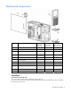
Mechanical components Item Description Original spare part number Modified spare part number Customer self repair (on page 5) 1 Access panel, tower 365058-001 — Yes 2 Access panel, rack* 371714-001 — Yes 3 Front bezel (tower model) 365064-001 ‡ 433940-001 See requirement Yes 4 Rack bezel* 390545-001 ‡ 409684-001 See requirement Yes 5 Removable media blank 231212-001 — Yes 6 Hard drive blank — — — a) SCSI hard drive blank 319602-001 — Yes b) SATA hard drive blank* 39261
If your unit contains a part that is labelled with the Original Spare number, please order the Original Spare as the replacement part in the EU. In this case either the Original Spare or the Modified Spare may be shipped which will not affect performance or functionality of the unit. §Directive 2002/95/EC restricts the use of lead, mercury, cadmium, hexavalent chromium, PBBs and PBDEs in electronic products.
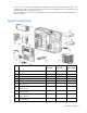
Item Description Original spare part number Modified spare part number Customer self repair (on page 5) 14 Processor power module 347884-001 — Yes 15 Hot-plug power supply, 725-W, 12-V 390394-001 ‡ 406413-001 See requirement Yes 390546-001 ‡ 409682-001 See requirement Yes Boards 16 System board 17 SCSI hard drive cage with simplex backplane 366862-001 18 Power supply backplane 390548-001 ‡ 433943-001 See requirement Yes 19 SATA/SAS hard drive cage* 390547-001 ‡ 409683-001 See requi
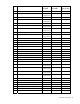
Description Original spare part number Modified spare part number Customer self repair (on page 5) b) 146-GB SCSI Ultra320, 10,000-rpm* 404708-001 — Yes c) 300-GB, SCSI Ultra320, 10,000-rpm* 404701-001 — Yes d) 80-GB SATA, 7,200-rpm* 399967-001 — Yes e) 160-GB SATA, 7,200-rpm* 399968-001 — Yes f) 250-GB SATA, 7,200-rpm* 399969-001 — Yes 35 Second Serial Port* 391183-001 ‡ 409685-001 See requirement Yes 36 Keyboard* 355630-001 — Yes 37 Mouse* 344704-001 — Yes Item *Not
Removal and replacement procedures In this section Required tools........................................................................................................................................ 10 Safety considerations.............................................................................................................................. 10 Preparation procedures...........................................................................................................................
Preventing electrostatic discharge To prevent damaging the system, be aware of the precautions you need to follow when setting up the system or handling parts. A discharge of static electricity from a finger or other conductor may damage system boards or other static-sensitive devices. This type of damage may reduce the life expectancy of the device. To prevent electrostatic damage: • Avoid hand contact by transporting and storing products in static-safe containers.
These symbols, on power supplies or systems, indicate that the equipment is supplied by multiple sources of power. WARNING: To reduce the risk of injury from electric shock, remove all power cords to completely disconnect power from the system. Rack warnings WARNING: To reduce the risk of personal injury or damage to the equipment, be sure that: • The leveling jacks are extended to the floor. • The full weight of the rack rests on the leveling jacks.
Extending the server from the rack 1. Loosen the thumbscrews that secure the server faceplate to the front of the rack. IMPORTANT: If the server is installed in a telco rack, remove the server from the rack to access internal components. 2. Extend the server on the rack rails until the server rail-release latches engage. WARNING: To reduce the risk of personal injury or equipment damage, be sure that the rack is adequately stabilized before extending a component from the rack.
Removing the server from the rack To remove the server from an HP, telco, or third-party rack: 1. Power down the server ("Powering down the server" on page 13). 2. Loosen the front panel thumbscrews that secure the server faceplate to the front of the rack. 3. Disconnect the cabling and remove the server from the rack. Reverse the server installation steps in the documentation that ships with the rack-mounting option. 4. Place the server on a sturdy, level surface.
To replace the component, reverse the removal procedure. Front bezel (tower model) This server has a removable front bezel that must be unlocked and opened before accessing the hard drive cage or removing the access panel. The door should be kept closed during normal server operations. Use the key provided with the server to unlock the bezel with a clockwise turn. If necessary, remove the front bezel. Rack rails NOTE: This procedure applies to rack servers only. To remove the component: 1.
2. Slide the rail forward and remove it from the server. 3. Repeat steps 1 and 2 to remove other rail. To replace the component, reverse the removal procedure. Power supply blank Loosen the thumbscrew that secures the redundant power supply blank, and then pull the blank from the back of the server. Hot-plug power supply WARNING: To reduce the risk of electric shock, do not disassemble the power supply or attempt to repair it. Replace it only with the specified spare part.
2. Push down on the power supply release latch, and remove the power supply from the server. CAUTION: To prevent improper cooling and thermal damage, do not operate the server unless all bays are populated with either a component or a blank. To replace the component, reverse the removal procedure. Hot-plug power supply backplane To remove the component: 1. Power down the server ("Powering down the server" on page 13). 2. Remove the power supplies from the server ("Hot-plug power supply" on page 16).
CAUTION: To prevent improper cooling and thermal damage, do not operate the server unless all bays are populated with either a component or a blank. SCSI hard drive blanks To remove the component: CAUTION: To prevent improper cooling and thermal damage, do not operate the server unless all bays are populated with either a component or a blank. NOTE: Depending on model purchased, the server may look slightly different than shown. To replace the component, reverse the removal procedure.
4. Remove the hard drive. To replace the component, reverse the procedure. Hot-plug SATA and SAS hard drives Hot-plug SATA and hot-plug SAS hard drives can be used interchangeably when a SAS controller is installed. Before installing a SAS hard drive, you must install a SAS controller. A SATA controller is embedded for use with SATA drives only.
5. Remove the hard drive. To replace the component: 1. Remove the existing hard drive blank or hard drive from the drive bay. 2. Install the hard drive. 3. Determine the status of the hard drive from the hot-plug hard drive LEDs ("Hot-plug SCSI hard drive LEDs" on page 49). 4. Resume normal server operations. Redundant system fan CAUTION: The redundant system fan is not hot-pluggable. To remove the redundant system fan: 1. Power down the server ("Powering down the server" on page 13). 2.
• Extend the server from the rack ("Extending the server from the rack" on page 13). 3. Remove the access panel ("Access panel" on page 14). 4. Disconnect the redundant system fan cable from the redundant system fan connector on the system board. 5. Remove the fan. To replace the component, reverse the removal procedure. Expansion slot cover To remove the component: 1. Power down the server ("Powering down the server" on page 13). 2. Do one of the following: 3.
4. Remove the expansion slot cover. CAUTION: To prevent improper cooling and thermal damage, do not operate the server unless all PCI slots have either an expansion slot cover or an expansion board installed. To replace the component, reverse the removal procedure. Expansion board CAUTION: To prevent damage to the server or expansion boards, power down the server and remove all AC power cords before removing or installing the expansion boards. To remove the component: 1.
4. Remove the expansion board retainer. 5. Disconnect any internal or external cables from the expansion board. 6. Remove the expansion board. 7. Reinstall the expansion board retainer, then tighten the thumbscrew. To replace the component, reverse the removal procedure. Half-height media device To remove the component: 1. Power down the server ("Powering down the server" on page 13). 2. Do one of the following: • Unlock and remove the bezel ("Front bezel (tower model)" on page 15).
5. Push up on the release lever and push the drive partially out through the front of the server. 6. Remove the media device. To replace the component, reverse the removal procedure. Tape drive To remove the component: 1. Power down the server ("Powering down the server" on page 13). 2. Do one of the following: • Unlock and remove the bezel ("Front bezel (tower model)" on page 15). • Extend the server from the rack ("Extending the server from the rack" on page 13). 3.
To replace the component, reverse the removal procedure. IMPORTANT: HP recommends installing the tape drive on a separate SCSI cable to avoid a decrease in performance on other SCSI devices. Internal two-bay hot-plug SCSI drive cage To remove the component: 1. Power down the server ("Powering down the server" on page 13). 2. Do one of the following: • Unlock and remove the bezel ("Front bezel (tower model)" on page 15).
To replace the component, reverse the removal procedure. IMPORTANT: Be sure that the unit identification numbers (0 and 1) appear on the right side of the drive cage front panel. Refer to the HP Internal Two-Bay Hot-Plug SCSI Drive Cage Installation Instructions for additional information. Processor and heatsink IMPORTANT: If upgrading processor speed, update the system ROM before installing the processor. IMPORTANT: PPM 2 must be installed when processor 2 is installed.
6. Remove the heatsink. 7. Open the processor locking lever and remove the processor. To replace the processor and heatsink: 1. Open the processor locking lever, if necessary. 2. Install the processor and close the processor locking lever.
CAUTION: Forcing the processor locking lever could lead to hardware damage. IMPORTANT: Do not remove the thermal tape from the bottom of the heatsink. Removing the tape will affect the thermal solution and prevent the system from working properly.
3. Install the heatsink. 4. Close the processor retaining brackets.
5. Connect the heatsink fan cable to the connector on the system board. Item Description 1 Processor 1 heatsink fan connector 2 Processor 2 heatsink fan connector 6. Install the access panel. PPM To remove the component: 1. Power down the server ("Powering down the server" on page 13). 2. Do one of the following: • Unlock and remove the bezel ("Front bezel (tower model)" on page 15). • Extend the server from the rack ("Extending the server from the rack" on page 13). 3.
NOTE: PPM 1 is embedded in the system board. NOTE: The appearance of compatible PPMs may vary. To replace the component, reverse the removal procedure. DIMM 1. Power down the server ("Powering down the server" on page 13). 2. Do one of the following: • Unlock and remove the bezel ("Front bezel (tower model)" on page 15). • Extend the server from the rack ("Extending the server from the rack" on page 13). 3. Remove the access panel ("Access panel" on page 14). 4. Open the DIMM slot latches. 5.
Second serial port To remove the component: 1. Power down the server ("Powering down the server" on page 13). 2. Do one of the following: • Unlock and remove the bezel ("Front bezel (tower model)" on page 15). • Extend the server from the rack ("Extending the server from the rack" on page 13). 3. Remove the access panel ("Access panel" on page 14). 4. Open the retention clip securing the second serial port. 5. Remove the serial port cable from the serial port header on the system board. 6.
4. Remove the SCSI cable from the duplex SCSI backplane and from either the array controller or the system board. 5. Remove the duplex SCSI backplane. To replace the component, reverse the removal procedure. Battery If the server no longer automatically displays the correct date and time, you may need to replace the battery that provides power to the real-time clock. Under normal use, battery life is 5 to 10 years.
• • • • Do not attempt to recharge the battery. Do not expose the battery to temperatures higher than 60°C (140°F). Do not disassemble, crush, puncture, short external contacts, or dispose of in fire or water. Replace only with the spare designated for this product. To remove the component: 1. Power down the server ("Powering down the server" on page 13). 2. Do one of the following: • Unlock and remove the bezel ("Front bezel (tower model)" on page 15).
7. Remove all expansion boards ("Expansion board" on page 22). 8. Remove the PPM for processor 2 ("PPM" on page 30). 9. Disconnect all cables connected to the system board. 10. Remove the four system board screws, and remove the system board. To replace the component, reverse the removal procedure. Server serial number and product ID After you replace the system board, you must re-enter the server serial number and the product ID. 1.
Diagnostic tools In this section Troubleshooting resources ....................................................................................................................... 36 Automatic Server Recovery ...................................................................................................................... 36 HP Systems Insight Manager....................................................................................................................
HP Systems Insight Manager HP SIM is a web-based application that allows system administrators to accomplish normal administrative tasks from any remote location, using a web browser. HP SIM provides device management capabilities that consolidate and integrate management data from HP and third-party devices. IMPORTANT: You must install and use HP SIM to benefit from the Pre-Failure Warranty for processors, SAS and SCSI hard drives, and memory modules.
• Viewing the current logical drive configuration • Deleting a logical drive configuration • Setting the controller to be the boot controller If you do not use the utility, ORCA will default to the standard configuration. For more information regarding array controller configuration, refer to the controller user guide. For more information regarding the default configurations that ORCA uses, refer to the HP ROM-Based Setup Utility User Guide on the Documentation CD.
IMPORTANT: This utility supports operating systems that may not be supported by the server. For operating systems supported by the server, refer to the HP website (http://www.hp.com/go/supportos).
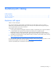
Server component identification In this section Front panel components .......................................................................................................................... 40 Front panel LEDs and buttons ................................................................................................................... 41 Rear panel components........................................................................................................................... 42 Rear panel LEDs ...
Front panel LEDs and buttons Item Description Status 1 UID LED Blue = Activated Flashing = System remotely managed Off = Deactivated 2 Internal health LED Green = Normal Amber = System degraded. Refer to system board LEDs (on page 47) to identify component in degraded state. Red = System critical. Refer to system board LEDs (on page 47) to identify component in critical state.
Rear panel components Item Description 1 Power cord connector 2 Optional hot-plug redundant power supply bay 3 SCSI connector knockouts 4 PCI Express slot 1 (x4, half-length) 5 PCI Express slot 2 (x8 (full-length) 6 PCI-X slot 3 (bus 9, 64-bit/100-MHz) 7 PCI-X slot 4 (bus 9, 64-bit/100-MHz) 8 PCI-X slot 5 (bus 6, 64-bit/133-MHz) 9 PCI-X slot 6 (bus 2, 64-bit/66-MHz) 10 iLO Management connector 11 RJ-45 Ethernet connector 12 USB 2.
Rear panel LEDs Item LED Status 1 Power supply LED Green = Power supply is on and functioning Off = No power or inadequate power supply 2 UID LED Blue = Activated Flashing = Remote inquiry Off = Deactivated 3 10/100/1000 On = Link NIC link LED Flashing = Activity Off = No link 4 5 10/100/1000 On = Standby NIC standby LED Off = Activity iLO NIC Activity LED On = Link Flashing = Activity Off = No link 6 iLO NIC standby LED On = Standby Off = Activity Server component identification 43
System board components NOTE: PPM 1 is embedded in the system board.
Item Description 25 Redundant fan connector 26 System fan connector 27 DIMM slot 6 (bank C) 28 DIMM slot 5 (bank C) 29 DIMM slot 4 (bank B) 30 DIMM slot 3 (bank B) 31 DIMM slot 2 (bank A) 32 DIMM slot 1 (bank A) NMI jumper The NMI jumper allows administrators to perform a memory dump before performing a hard reset. Crash dump analysis is an essential part of eliminating reliability problems, such as hangs or crashes in operating systems, device drivers, and applications.
System LEDs and internal health LED combinations When the internal health LED on the front panel illuminates either amber or red, the server is experiencing a health event. Combinations of illuminated system LEDs and the internal health LED indicate system status. The front panel health LEDs indicate only the current hardware status. In some situations, HP SIM may report server status differently than the health LEDs because the software tracks more system attributes.
System board LEDs Item LED description Status 1 AC power Off = No AC power or failed power supply Green = Power supply is on and functioning 2 3 Processor 1 fan status Off = Processor fan is functioning Processor 1 status Off = Processor 1 functioning Amber = Fan is not installed or has failed Amber = Processor 1 failed 4 5 6 PPM 1 (embedded) status Off = PPM 1 is functioning Processor 2 fan status Off = Processor fan is functioning Processor 2 status Off = Processor 1 is functioning Amb
Item LED description Status 13 DIMM 6 status Off = DIMM 6 is functioning Amber = DIMM 6 has failed 14 DIMM 5 status Off = DIMM 5 is functioning Amber = DIMM 5 has failed 15 DIMM 4 status Off = DIMM 4 is functioning 16 DIMM 3 status Off = DIMM 3 is functioning Amber = DIMM 4 has failed Amber = DIMM 3 has failed 17 DIMM 2 status Off = DIMM 2 is functioning Amber = DIMM 2 has failed 18 DIMM 1 status Off = DIMM 1 is functioning Amber = DIMM 1 has failed Hot-plug hard drive IDs SCSI models o
Item Description 2 Hot-plug SATA hard drive cage (SAS-enabled) Hot-plug SCSI hard drive LEDs Item LED description Status 1 Activity status On = Drive activity Flashing = High activity on the drive or drive is being configured as part of an array. Off = No drive activity 2 Online status On = Drive is part of an array and is currently working. Flashing = Drive is actively online. Off = Drive is offline.
SATA or SAS hard drive LEDs Item LED description Status 1 Online/Activity status Green = Drive activity Flashing green = High activity on the drive or drive is being configured as part of an array Off = No drive activity 2 Fault/UID status Amber = Drive failure Flashing amber = Fault-process activity Blue = Unit identification is active Off = No fault-process activity Server component identification 50
Specifications In this section Tower server specifications...................................................................................................................... 51 Rack server specifications........................................................................................................................ 51 Environmental specifications ....................................................................................................................
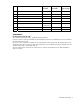
Models with a redundant power supply Input requirements Rated input voltage 100 VAC to 240 VAC Rated input frequency 47 Hz to 63 Hz Rated input current 10 A (110 V) to 5 A (220 V) Rated input power 893 W BTUs per hour 3049 Power supply output Rated steady-state power 725 W Maximum peak power 725 W Environmental specifications Specification Value Temperature range* Operating 10°C to 35°C (50°F to 95°F) Shipping -40°C to 70°C (-40°F to 158°F) Maximum wet bulb temperature 28°C (82.
1.44-MB diskette drive specifications Specification Value Dimensions Height 12.7 mm (0.5 in) Width 96 mm (3.8 in) Depth 130 mm (5.1 in) LEDs (front panel) Green = Active Read/write capacity per diskette High density 1.
Specification Value Width 132.08 mm (5.20 in) Weight 0.34 kg (0.75 lb) Data transfer rate Sustained 150 KB/s (sustained 1X), 1500/3600 KB/s (10X to 24X) Burst 16.6 MB/s Access times (typical) Full stroke 300 ms Random 140 ms Diameter 12 cm, 8 cm (4.70 in, 3.15 in) Thickness 1.2 mm (0.05 in) Track pitch 1.6 µm (6.
Acronyms and abbreviations ABEND abnormal end ACU Array Configuration Utility ADU Array Diagnostics Utility ASR Automatic Server Recovery ATAPI Advanced Technology Attachment Packet Interface DDR double data rate DIMM dual inline memory module HD68 high density 68 IEC International Electrotechnical Commission iLO Integrated Lights-Out IML Integrated Management Log IPL initial program load Acronyms and abbreviations 55
IRQ interrupt request ISEE Instant Support Enterprise Edition MPS multi-processor specification NEMA National Electrical Manufacturers Association NFPA National Fire Protection Association NIC network interface controller NMI non-maskable interrupt NVRAM non-volatile memory ORCA Option ROM Configuration for Arrays PCI Express peripheral component interconnect express PCI-X peripheral component interconnect extended PDU power distribution unit POST Power-On Self Test PPM processor power module
PSP ProLiant Support Pack PXE Preboot Execution Environment RBSU ROM-Based Setup Utility RILOE II Remote Insight Lights-Out Edition II SAS serial attached SCSI SATA serial ATA SCSI small computer system interface SDRAM synchronous dynamic RAM SIM Systems Insight Manager TMRA recommended ambient operating temperature UID unit identification VHDCI very high density cable interconnect WOL Wake-on LAN Acronyms and abbreviations 57
Index A access panel 14 Altiris Deployment Solution 37 Altiris eXpress Deployment Server 37 ASR (Automatic Server Recovery) 35, 54 Automatic Server Recovery (ASR) 35, 54 Autorun menu 38 B Basic Input/Output System (BIOS) 37 battery 32 BIOS (Basic Input/Output System) 37 BIOS upgrade 37 buttons 39 C CD-ROM drive 22, 52 component identification 39, 48 components 39 components, mechanical 6 components, system 7 configuration of system 37 connectors 39 creating a disk image 37 CSR (customer self repair) 5 cus
LEDs 39 LEDs, hard drive 48 M management tools 35 mechanical components 6 media devices 22, 23 N network interface controller (NIC) 55 NMI jumper 44 O Online ROM Flash Component Utility 37 Option ROM Configuration for Arrays (ORCA) 36 P part numbers 5 Power On/Standby button 13 power requirements 51 power supplies 16, 51 power supply blank 16 power supply output 51 powering down 13 PPM (processor power module) 29 preparation procedures 12 Processor Power Module (PPM) 29 processors 25 ProLiant Support Pa