HP ProLiant ML350p Gen8 Server User Guide Abstract This document is for the person who installs, administers, and troubleshoots servers and storage systems. This document is intended for experienced IT professionals or end-users with no or prior hardware setup experience. HP assumes you are qualified in the servicing of computer equipment and trained in recognizing hazards in products with hazardous energy levels.
© Copyright 2012, 2014 Hewlett-Packard Development Company, L.P. The information contained herein is subject to change without notice. The only warranties for HP products and services are set forth in the express warranty statements accompanying such products and services. Nothing herein should be construed as constituting an additional warranty. HP shall not be liable for technical or editorial errors or omissions contained herein. Microsoft® and Windows® are U.S.
Contents Component identification ............................................................................................................... 7 Front panel components ............................................................................................................................. 7 Front panel LEDs and buttons ...................................................................................................................... 8 Rear panel components .........................................
Installing the server into the rack................................................................................................................ 36 Powering up and configuring the server ..................................................................................................... 43 Installing the operating system................................................................................................................... 43 Registering the server ............................................
HP iLO Management ............................................................................................................................. 111 HP iLO ....................................................................................................................................... 111 Intelligent Provisioning .................................................................................................................. 113 HP Insight Remote Support software ......................................
Customer Self Repair ............................................................................................................................. 131 Acronyms and abbreviations ...................................................................................................... 139 Documentation feedback ........................................................................................................... 142 Index .....................................................................................
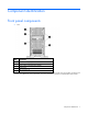
Component identification Front panel components • SFF Item Description 1 Media/Drive cage bay 2 SAS/SATA drives (8) 3 Serial number/iLO information pull tab* 4 Optical drive 5 USB connectors (4) *The serial number/iLO information pull tab is double-sided. The top side shows the server serial number, and the reverse side shows the default iLO account information. The same information is printed on a label attached to the chassis.
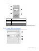
• LFF Item Description 1 Media/Drive cage bay 2 SAS/SATA drive (6) 3 Serial number/iLO information pull tab* 4 Optical drive 5 USB connectors (4) *The serial number/iLO information pull tab is double-sided. The top side shows the server serial number, and the reverse side shows the default iLO account information. The same information is printed on a label attached to the chassis.
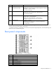
Item Description Status 1 Power On/Standby button and system power LED Solid green = System on Flashing green (1 Hz/cycle per sec) = Performing power on sequence Solid amber = System in standby Off = No power present* 2 NIC status LED Solid green = Link to network Flashing green (1 Hz/cycle per sec) = Network active Off = No network activity 3 Health LED Solid green = Normal Flashing amber = System degraded Flashing red (1 Hz/cycle per sec) = System critical Fast-flashing red (4 Hz/cycles per sec
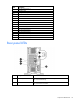
Item Description 8 PCIe slot 4 (Processor 1) 9 UID button/LED 10 Kensington security lock 11 Serial connector 12 iLO connector 13 NIC connector 3 14 NIC connector 4 15 NIC connector 2 16 NIC connector 1 17 USB connectors (4) 18 Video connector 19 PCIe slot 5 (Processor 2) 20 PCIe slot 6 (Processor 2) 21 PCIe slot 7 (Processor 2) 22 PCIe slot 8 (Processor 2) 23 PCIe slot 9 (Processor 2) Rear panel LEDs Item Description Status 1 NIC activity LED Green or flashing green
Item Description Status 3 Power supply LED Green = Normal Off = One or more of the following conditions exists: • • • • Power Power Power Power is unavailable. supply failed. supply is in standby mode. supply exceeded current limit.
Item Description 13 Internal USB tape connector 14 Discovery service cable connector 15 System battery 16 SATA connectors 17 Internal USB connector 18 Processor 2 DIMM slots 19 TPM connector 20 System maintenance switch 21 NMI header 22 Slot 9 PCIe3 x8 (4, 1) 23 Slot 8 PCIe3 x16 ( 16, 8, 4, 1) 24 Slot 7 PCIe3 x8 (4, 1) 25 Slot 6 PCIe3 x16 (16, 8, 4, 1) 26 Slot 5 PCIe2 x8 (4, 1) 27 Processor 1 DIMM slots 28 Processor socket 1 (populated) DIMM slots DIMM slots are numbered se
System maintenance switch Position Default Function S1 Off Off = iLO 4 security is enabled. On = iLO 4 security is disabled. S2 Off Off = System configuration can be changed. On = System configuration is locked. S3 Off Reserved S4 Off Reserved S5 Off Off = Power-on password is enabled. On = Power-on password is disabled. S6 Off Off = No function On = ROM reads system configuration as invalid.
Systems Insight Display LEDs The HP Systems Insight Display LEDs represent the system board layout. Item Description Status 1 Power cap To determine Power cap status, see "Systems Insight Display LED combinations (on page 14)." 2 AMP Status Green = AMP mode enabled Amber = Failover Off = AMP mode disabled 3 DIMM LEDs Amber = DIMM error Off = Normal All other LEDs Amber = Failure Off = Normal IMPORTANT: If more than one DIMM slot LED is illuminated, further troubleshooting is required.
Systems Insight Display Health LED LED and color Processor (amber) Red System power LED Status Amber One or more of the following conditions might exist: • • • • Processor in socket X has failed. Processor X is not installed in the socket. Processor X is unsupported. ROM detects a failed processor during POST Processor (amber) Amber Green Processor in socket X is in a pre-failure condition. DIMM (amber) Red Green One or more DIMMs have failed.
HP recommends that you populate drive bays starting with the lowest SAS or SATA device number. Drives are numbered from left to right in each component box. Component boxes are numbered 1 through 3, from bottom to top.
Hot-plug drive LED definitions Item LED Status 1 Locate Solid blue The drive is being identified by a host application. Flashing blue The drive carrier firmware is being updated or requires an update. Rotating green Drive activity Off No drive activity Solid white Do not remove the drive. Removing the drive causes one or more of the logical drives to fail. Off Removing the drive does not cause a logical drive to fail. Solid green The drive is a member of one or more logical drives.
Item Description Configuration 1 Fan 1 Redundant 2 Fan 2 Primary 3 Fan 3 Primary 4 Fan 4 Primary RPS riser board connectors Item Connector Description 1 J7 Graphic card power connector 2 J9 Drive backplane bay 1/optical drive power connector 3 J5 Drive backplane bay 2 power connector 4 J6 Drive backplane bay 3 power connector Component identification 18
Item Connector Description 5 J8 Graphic card power connector Component identification 19
Operations Power up the server To power up the server: 1. Connect each power cord to the server. 2. Connect each power cord to the power source. 3. Press the Power On/Standby button. The server exits standby mode and applies full power to the system. The system power LED changes from amber to green. Power down the server Before powering down the server for any upgrade or maintenance procedures, perform a backup of critical server data and programs.
Remove the security bezel Unlock the security bezel, press the latch on the security bezel, and then remove the security bezel. Install the security bezel Install the security bezel into the chassis, and then lock the security bezel with the key. Remove the tower bezel This server has a removable bezel that must be unlocked and opened before accessing the drives. The bezel must be kept closed during normal server operations.
1. Using the key provided with the server, unlock the bezel with a clockwise turn. 2. Remove the tower bezel. Remove the rack bezel 1. If installed, remove the security bezel (on page 21). 2. Power down the server (on page 20). 3. Remove all power: a. Disconnect each power cord from the power source. b. Disconnect each power cord from the server. 4. Extend the server from the rack (on page 24). 5. Remove the access panel (on page 23). 6.
7. Remove the rack bezel. Install the rack bezel 1. Install the rack bezel. 2. Tighten the rack bezel thumbscrews. 3. Install the access panel (on page 24). 4. Slide the server back into the rack. Remove the access panel WARNING: To reduce the risk of personal injury from hot surfaces, allow the drives and the internal system components to cool before touching them.
CAUTION: Do not operate the server for long periods with the access panel open or removed. Operating the server in this manner results in improper airflow and improper cooling that can lead to thermal damage. To remove the component: 1. Do one of the following: o For tower models, open and remove the bezel ("Remove the tower bezel" on page 21). o For rack models, if installed, remove the security bezel (on page 21). 2. Power down the server (on page 20). 3. Remove all power: a.
WARNING: To reduce the risk of personal injury or equipment damage, be sure that the rack is adequately stabilized before extending a component from the rack. WARNING: To reduce the risk of personal injury, be careful when pressing the server rail-release latches and sliding the server into the rack. The sliding rails could pinch your fingers. 3.
6. Remove the air baffle. Install the air baffle CAUTION: For proper cooling, do not operate the server without the access panel, baffles, expansion slot covers, or blanks installed. If the server supports hot-plug components, minimize the amount of time the access panel is open. 1. Install the air baffle. 2. Install the access panel (on page 24). 3. Do one of the following: o For tower models, install the bezel. o For rack models, if removed, install the security bezel (on page 21).
Remove the fan CAUTION: To prevent improper cooling and thermal damage, do not operate the server unless all bays are populated with either a component or a blank. To remove the component: 1. Do one of the following: o For tower models, open and remove the bezel ("Remove the tower bezel" on page 21). o For rack models, if installed, remove the security bezel (on page 21). 2. Power down the server (on page 20). 3. Remove all power: a. Disconnect each power cord from the power source. b.
To remove the component: 1. Do one of the following: o For tower models, open and remove the bezel ("Remove the tower bezel" on page 21). o For rack models, if installed, remove the security bezel (on page 21). 2. Power down the server (on page 20). 3. Remove all power: a. Disconnect each power cord from the power source. b. Disconnect each power cord from the server. 4. Do one of the following: o For tower models, place the server on a flat, level surface with the access panel facing up.
a. Place the server on a flat, level surface with the access panel facing up. b. Remove the access panel (on page 23). 5. For rack models, do the following: a. Extend the server from the rack (on page 24). b. Remove the access panel (on page 23). c. Release thumbscrews and remove the rack bezel. 6. Remove the fan cage. 7. Disconnect and remove the optical drive power and data cables. 8. Remove the optical drive. Remove the component drive cage blank 1.
Operations 30
Setup Optional installation services Delivered by experienced, certified engineers, HP Care Pack services help you keep your servers up and running with support packages tailored specifically for HP ProLiant systems. HP Care Packs let you integrate both hardware and software support into a single package. A number of service level options are available to meet your needs.
Space and airflow requirements Tower server In a tower configuration, leave at least a 7.6-cm (3-in) clearance space at the front and back of the server for proper ventilation. Rack server To allow for servicing and adequate airflow, observe the following space and airflow requirements when deciding where to install a rack: • Leave a minimum clearance of 63.5 cm (25 in) in front of the rack. • Leave a minimum clearance of 76.2 cm (30 in) behind the rack. • Leave a minimum clearance of 121.
CAUTION: To reduce the risk of damage to the equipment when installing third-party options: • Do not permit optional equipment to impede airflow around the server or to increase the internal rack temperature beyond the maximum allowable limits. • Do not exceed the manufacturer’s TMRA. Power requirements Installation of this equipment must comply with local and regional electrical regulations governing the installation of information technology equipment by licensed electricians.
WARNING: To reduce the risk of personal injury or damage to the equipment, be sure that: • • • • • The leveling jacks are extended to the floor. The full weight of the rack rests on the leveling jacks. The stabilizing feet are attached to the rack if it is a single-rack installation. The racks are coupled together in multiple-rack installations. Only one component is extended at a time. A rack may become unstable if more than one component is extended for any reason.
Identifying tower server shipping carton contents Unpack the server shipping carton and locate the materials and documentation necessary for installing the server.
2. Return the server to an upright position. 3. Connect peripheral devices to the server. WARNING: To reduce the risk of electric shock, fire, or damage to the equipment, do not plug telephone or telecommunications connectors into RJ-45 connectors. 4. Connect the power cord to the rear of the server. 5. Connect the power cord to the AC power source. WARNING: To reduce the risk of electric shock or damage to the equipment: • Do not disable the power cord grounding plug.
7. Remove the server base feet. 8. Remove all screws securing the base cover to the chassis. 9. Place two Torx screwdrivers in the bezel hinge holes to help slide the base cover towards the rear of the server, and then remove the base cover.
10. Install the server base blank covers over the server base feet holes. 11. Turn the server over, and then remove the access panel ("Remove the access panel" on page 23).
12. Remove the air baffle. 13. Remove the fan cage.
14. Remove the knock-out bracket, install the System Insight Display module, and then route the cable. 15. Connect the cable from the System Insight Display module to the front input/output cable. 16. Remove the blank or cage installed in component box 3.
17. Install the left and right rack bezels ears with T-10 and T-15 screws. 18. Route the discovery service cable from the left rack bezel ear through the chassis hooks.
19. Connect the discovery service cable to the discovery service cable connector. 20. Install the blank or cage removed from component box 3. 21. Install and lock the rack bezel ("Install the rack bezel" on page 23). 22. Install the fan cage. 23. Install the air baffle (on page 26).
24. Install the access panel (on page 24). 25. Install the server on the rack rail, and then slide the assembly into the rack. NOTE: For detailed instructions on installing the server into the rack, see the Quick Deploy Rail System Installation Instructions included with the kit. Powering up and configuring the server To power up the server: 1. Connect each power cord to the server. 2. Connect each power cord to the power source. 3. Press the Power On/Standby button.
To operate properly, the server must have a supported operating system. For the latest information on operating system support, see the HP website (http://www.hp.com/go/supportos). To install an operating system on the server, use one of the following methods: • Intelligent Provisioning—The iLO Management Engine is a new feature on ProLiant servers that contains Intelligent Provisioning for embedded deployment, updating, and provisioning capabilities.
Hardware options installation Introduction If more than one option is being installed, read the installation instructions for all the hardware options and identify similar steps to streamline the installation process. WARNING: To reduce the risk of personal injury from hot surfaces, allow the drives and the internal system components to cool before touching them. CAUTION: To prevent damage to electrical components, properly ground the server before beginning any installation procedure.
o Cable routing to box 1 o Cable routing to box 2 Hardware options installation 46
o Cable routing to box 3 11. Install the fan cage. 12. Install the air baffle (on page 26). 13. For tower models, do the following: a. Install the access panel (on page 24). b. Return the server to an upright position. 14. For rack models, do the following: a. Install the access panel (on page 24). b. Slide the server into the rack. 15. Connect each power cord to the server. 16. Connect each power cord to the power source. 17. Press the Power On/Standby button.
IMPORTANT: If installing a processor with a faster speed, update the system ROM before installing the processor. To install a processor: 1. Do one of the following: o For tower models, open and remove the bezel ("Remove the tower bezel" on page 21). o For rack models, if installed, remove the security bezel (on page 21). 2. Power down the server (on page 20). 3. Remove all power: a. Disconnect each power cord from the power source. b. Disconnect each power cord from the server. 4.
8. Remove the clear processor socket cover. Retain the processor socket cover for future use. 9. Install the processor. Verify that the processor is fully seated in the processor retaining bracket by visually inspecting the processor installation guides on either side of the processor. THE PINS ON THE SYSTEM BOARD ARE VERY FRAGILE AND EASILY DAMAGED. CAUTION: THE PINS ON THE SYSTEM BOARD ARE VERY FRAGILE AND EASILY DAMAGED.
CAUTION: Do not press down on the processor. Pressing down on the processor may cause damage to the processor socket and the system board. Press only in the area indicated on the processor retaining bracket. 11. Press and hold the processor retaining bracket in place, and then close each processor locking lever. Press only in the area indicated on the processor retaining bracket. CAUTION: Close and hold down the processor cover socket while closing the processor locking levers.
14. Install the heatsink, and then close the heatsink retaining levers. 15. Install the air baffle (on page 26).
16. Remove the fan blank. 17. Install the fan, making sure that the fan clicks into place. 18. Install the access panel (on page 24). 19. Do one of the following: o For tower models, return the server to an upright position. o For rack models, slide the server back into the rack. 20. Connect each power cord to the server. 21. Connect each power cord to the power source. 22. Press the Power On/Standby button. The server exits standby mode and applies full power to the system.
o For rack models, if removed, install the security bezel (on page 21). Processor upgrade WARNING: To reduce the risk of personal injury from hot surfaces, allow the drives and the internal system components to cool before touching them. CAUTION: To prevent possible server malfunction and damage to the equipment, multiprocessor configurations must contain processors with the same part number.
7. Open the heatsink retaining levers. 8. Remove the heatsink. 9. Remove the heatsink retaining levers.
10. Open each of the processor locking levers in the order indicated, and then open the processor retaining bracket. 11. Remove the processor from the processor retaining bracket. CAUTION: To avoid damage to the processor, do not touch the bottom of the processor, especially the contact area.
To install a processor: 1. Install the processor. Verify that the processor is fully seated in the processor retaining bracket by visually inspecting the processor installation guides on either side of the processor. THE PINS ON THE SYSTEM BOARD ARE VERY FRAGILE AND EASILY DAMAGED. CAUTION: THE PINS ON THE SYSTEM BOARD ARE VERY FRAGILE AND EASILY DAMAGED. To avoid damage to the system board, do not touch the processor or the processor socket contacts. 2. Close the processor retaining bracket.
3. Press and hold the processor retaining bracket in place, and then close each processor locking lever. Press only in the area indicated on the processor retaining bracket. 4. Install the heatsink retaining lever upgrade. 5. Use the alcohol swab to remove all the existing thermal grease from the heatsink. Allow the alcohol to evaporate before continuing.
6. Apply the thermal grease to the top of the processor in the following pattern. 7. Install the heatsink, and then close the heatsink retaining levers. 8. Install the air baffle. 9. Install the access panel (on page 24). 10. Do one of the following: o For tower models, return the server to an upright position. o For rack models, slide the server back into the rack. 11. Connect each power cord to the server. 12. Connect each power cord to the power source. 13.
Memory options IMPORTANT: This server does not support mixing LRDIMMs, RDIMMs, or UDIMMs. Attempting to mix any combination of these DIMMs can cause the server to halt during BIOS initialization. The memory subsystem in this server can support LRDIMMs, RDIMMs, or UDIMMs: • UDIMMs represent the most basic type of memory module and offer lower latency in one DIMM per channel configurations and (relatively) low power consumption, but are limited in capacity.
Populated DIMM speed (MT/s) DIMM type DIMM rank 2 slots per channel 1 DPC — — 1.35 V 3 slots per channel 2 DPC 3 DPC 1.50 V 1.35 V 1.50 V 1.35 V 1.
Memory subsystem channel Population order Slot number (Processor Slot number (Processor 2) 1) 1 A E I 12 11 10 1 2 3 2 B F J 9 8 7 4 5 6 3 C G K 1 2 3 12 11 10 4 D H L 4 5 6 9 8 7 For the location of the slot numbers, see "DIMM slots (on page 12)." This multi-channel architecture provides enhanced performance in Advanced ECC mode. This architecture also enables Lockstep and Online Spare Memory modes. DIMM slots in this server are identified by number and by letter.
o For rack models, extend the server from the rack (on page 24). 5. Remove the access panel (on page 23). 6. Remove the air baffle (on page 25). 7. Open the DIMM slot latches. 8. Install the DIMM. If you are installing DIMMs in lock-step configuration, configure this mode in RBSU ("HP ROM-Based Setup Utility" on page 115). For more information about LEDs and troubleshooting failed DIMMs, see Systems Insight Display LED combinations (on page 14).
DIMM identification To determine DIMM characteristics, use the label attached to the DIMM and the following illustration and table. Item Description Definition 1 Size — 2 Rank 1R 2R 3R 4R 3 Data width x4 = 4-bit x8 = 8-bit 4 Voltage rating L = Low voltage (1.35V) U = Ultra low voltage (1.
is degrading. This allows DIMMs that have a higher probability of receiving an uncorrectable memory error (which would result in system downtime) to be removed from operation. Advanced Memory Protection options are configured in RBSU. If the requested AMP mode is not supported by the installed DIMM configuration, the server boots in Advanced ECC mode. For more information, see "HP ROM-Based Setup Utility (on page 115).
Lockstep memory configuration Lockstep mode provides protection against multi-bit memory errors that occur on the same DRAM device. Lockstep mode can correct any single DRAM device failure on x4 and x8 DIMM types. The DIMMs in each channel must have identical HP part numbers. General DIMM slot population guidelines Observe the following guidelines for all AMP modes: • Install DIMMs only if the corresponding processor is installed.
• Each populated channel must have a spare rank: o A single dual-rank DIMM is not a valid configuration. o LRDIMMs are treated as dual-rank DIMMs. Lockstep Memory population guidelines For Lockstep memory mode configurations, observe the following guidelines: • Observe the general DIMM slot population guidelines. • DIMM configuration on all channels of a processor must be identical. • In multi-processor configurations, each processor must have a valid Lockstep Memory configuration.
6. Remove the blank from box 3. 7. Install the optical drive cage.
8. Using the T-15 screws, secure the optical drive cage. 9. The Torx screws required to install optical drives are located on the chassis. 10. For tower models, do the following: a. Install the access panel (on page 24). b. Return the server to an upright position. 11. For rack models, do the following: a. Install the rack bezel (on page 23). b. Install the access panel (on page 24). c. Slide the server back into the rack. 12. Connect each power cord to the server. 13.
The server exits standby mode and applies full power to the system. The system power LED changes from amber to green. 15. Do one of the following: o For tower models, install the bezel. o For rack models, if removed, install the security bezel (on page 21). Optical drive option The server supports both DVD-ROM and DVD-RW drives. 1. Do one of the following: o For tower models, open and remove the bezel ("Remove the tower bezel" on page 21).
7. Install the optical drive into the drive cage. 8. Remove the air baffle (on page 25). 9. Remove the fan cage. 10. Connect the power cable from the drive to the system board. 11. Connect the SATA cable from the drive to the system board. 12. Install the fan cage. 13. Install the air baffle (on page 26). 14. For tower models, do the following: a. Install the access panel (on page 24). b. Return the server to an upright position. 15. For rack models, do the following: a.
b. Install the access panel (on page 24). c. Slide the server back into the rack. 16. Connect each power cord to the server. 17. Connect each power cord to the power source. 18. Press the Power On/Standby button. The server exits standby mode and applies full power to the system. The system power LED changes from amber to green. 19. Do one of the following: o For tower models, install the bezel. o For rack models, if removed, install the security bezel (on page 21).
3. Insert the power supply into the power supply bay until it clicks into place. 4. Connect the power cord to the power supply. 5. For rack servers, use the strain relief clip from the server hardware kit to secure the power cord. 6. Connect the power cord to the power source. 7. Be sure that the power supply LED is green. Hot-plug SAS drive options When adding drives to the server, observe the following general guidelines: • The system automatically sets all device numbers.
2. o For tower models, open and remove the bezel ("Remove the tower bezel" on page 21). o For rack models, if installed, remove the security bezel (on page 21). Remove the drive blank. Installing a hot-plug drive WARNING: To reduce the risk of injury from electric shock, do not install more than one drive carrier at a time. The server can support six drives in a LFF configuration, or eight drives in a SFF configuration. To install the component: 1. 2.
3. Prepare the drive. 4. Install the drive. 5. Determine the status of the drive from the drive LED definitions ("Hot-plug drive LED definitions" on page 17). 6. Do one of the following: o For tower models, install the bezel. o For rack models, if removed, install the security bezel (on page 21). Expansion board option 1. Do one of the following: o For tower models, open and remove the bezel ("Remove the tower bezel" on page 21).
7. Open the PCIe retainer latch. 8. Do one of the following: a. If you are installing a single-width expansion card, remove one PCIe blank. b. If you are installing a double-width expansion card, remove two PCIe blanks.
9. Install the expansion board. 10. Close the PCIe retainer latch. 11. Install the air baffle (on page 26). 12. Install the access panel (on page 24). 13. Do one of the following: o For tower models, return the server to an upright position. o For rack models, slide the server back into the rack. 14. Connect each power cord to the server. 15. Connect each power cord to the power source. 16. Press the Power On/Standby button.
o For tower models, install the bezel. o For rack models, if removed, install the security bezel (on page 21). Graphic card option The server supports up to three graphic card options. The server supports up to two double-wide graphic cards. For optimal performance, HP recommends that you install graphic card options in PCI slots 3, 6, or 8. HP recommends the following: • If the graphic card is populated in PCI slot 3, do not use PCI slot 2.
9. Open the PCIe retainer latch. 10. Do one of the following: o If you are installing a single-width graphic card adapter, remove one PCIe blank. o If you are installing a double-width graphic card adapter, remove two PCIe blanks.
11. Install the graphic adapter in a x16 PCIe expansion slot. 12. Connect the graphic card adapter cable to the appropriate graphic card connector. NOTE: For more information about installing a graphic card, see the documentation that ships with the graphic card option kit.
13. Close the PCIe retainer latch. NOTE: Install the graphic card bracket only if you have installed a double-width graphic card. 14. Install the graphic card bracket, and then tighten the screws. 15. Install the fan cage. 16. Install the air baffle (on page 26). 17. Install the access panel (on page 24). 18. Do one of the following: o For tower models, return the server to an upright position. o For rack models, slide the server back into the rack. 19. Connect each power cord to the server.
21. Press the Power On/Standby button. The server exits standby mode and applies full power to the system. The system power LED changes from amber to green. 22. Do one of the following: o For tower models, install the bezel. o For rack models, if removed, install the security bezel (on page 21). Controller option The server ships with an embedded Smart Array P420i Controller.
Installing a storage controller IMPORTANT: For additional installation and configuration information, see the documentation that ships with the option. IMPORTANT: The P822 controller card is only supported in PCIe slots 3 and 4. If the controller card is configured in PCIe slot 3, slot 4 must remain empty. IMPORTANT: The P420 controller card is not supported in PCIe slots 3 and 4. IMPORTANT: The P222 controller card is only supported in two processor configuration.
The server exits standby mode and applies full power to the system. The system power LED changes from amber to green. 18. Do one of the following: o For tower models, install the bezel. o For rack models, if removed, install the security bezel (on page 21). For more information about the storage controller and its features, select the relevant controller user documentation on the HP website (http://www.hp.com/go/smartstorage/docs).
8. Install the cache module. 9. Install the capacitor pack into the server. 10. Store the extra cable near the capacitor pack. 11.
o Cache module on the Smart Array option 12. Install the fan cage. 13. Install the air baffle (on page 26). 14. Install the access panel (on page 24). 15. Do one of the following: o For tower models, return the server to an upright position. o For rack models, slide the server back into the rack. 16. Connect each power cord to the server. 17. Connect each power cord to the power source. 18. Press the Power On/Standby button.
• If two fans fail, then the server shuts down. IMPORTANT: Fan louvers must be present for the redundant configuration. Without the louvers, all four fans are nonredundant. NOTE: If your system is already installed with four fans, store the fan that is included in this kit as a spare. Installing a hot-plug redundant fan 1. Do one of the following: o For tower models, open and remove the bezel ("Remove the tower bezel" on page 21).
7. Install the fan louvers, making sure that the louver click into place. 8. Remove the tab from each fan.
9. Install the fans, making sure that the fans click into place. 10. Install the PCIe air baffles. 11. Install the access panel (on page 24). 12. Do one of the following: o For tower models, return the server to an upright position. o For rack models, slide the server back into the rack. 13. Connect each power cord to the server. 14. Connect each power cord to the power source. 15. Press the Power On/Standby button. The server exits standby mode and applies full power to the system.
o For rack models, if removed, install the security bezel (on page 21). Eight-bay SFF drive cage option Install the optional eight-bay SFF drive cage in drive cage bay 2 or drive cage bay 3. To install an additional eight-bay SFF drive cage, an optional SAS controller is required. To obtain the option, contact an HP authorized reseller. Installing the optional SFF hot-plug drive cage 1. Do one of the following: o For tower models, open and remove the bezel ("Remove the tower bezel" on page 21).
7. Install the optional SFF drive cage. 8. Using the T-15 screws, secure the optional SFF drive cage to the server. 9. Remove the air baffle (on page 25). 10. Remove the fan cage.
11. Connect the mini-SAS cables to the drive cage backplane option. 12. Connect the mini-SAS cables to the SAS controller option. NOTE: For more information about connecting the cables to SAS controller option, see the documentation that ships with SAS controller option kit. 13. Connect the power cable to the system board connector appropriate for your configuration. 14. Install the fan cage. 15. Install the air baffle (on page 26). 16. For tower models, do the following: a.
b. Install the access panel (on page 24). c. Slide the server back into the rack. 18. Connect each power cord to the server. 19. Connect each power cord to the power source. 20. Press the Power On/Standby button. The server exits standby mode and applies full power to the system. The system power LED changes from amber to green. 21. Do one of the following: o For tower models, install the bezel. o For rack models, if removed, install the security bezel (on page 21).
6. Remove the blank from box 2 or box 3. 7. Install the optional LFF hot-plug drive cage.
8. Using the T-15 screws, secure the optional LFF drive cage to the server. 9. Remove the air baffle (on page 25). 10. Remove the fan cage. 11. Connect the mini-SAS cables to the drive backplane option. 12. Connect the mini-SAS cables to the SAS controller option. NOTE: For more information about connecting the cables to SAS controller option, see the documentation that ships with SAS controller option kit.
13. Connect the power cable to the appropriate connector on the system board for your configuration. 14. Install the fan cage. 15. Install the air baffle (on page 26). 16. For tower models, do the following: a. Install the access panel (on page 24). b. Return the server to an upright position. 17. For rack models, do the following: a. Install the rack bezel (on page 23). b. Install the access panel (on page 24). c. Slide the server back into the rack. 18. Connect each power cord to the server.
Installing the 6 bay LFF drive backplane expander 1. Do one of the following: o For tower models, open and remove the bezel ("Remove the tower bezel" on page 21). o For rack models, if installed, remove the security bezel (on page 21). 2. Power down the server (on page 20). 3. Remove all power: a. Disconnect each power cord from the power source. b. Disconnect each power cord from the server. 4. For tower models, do the following: a.
7. Install the LFF drive cage with backplane expander option halfway into the server. 8. Remove the air baffle (on page 25). 9. Remove the fan cage. 10. Connect the power cables from the backplane expander kit option to the power connectors on the system board.
o Installing two backplanes with expander option 11. Disconnect all the existing mini-SAS cables from the server. 12. Connect the mini-SAS cables from the backplane expander option to the connectors on the system board.
i. Connect the short mini-SAS cables. ii. Connect the long mini-SAS cables.
13. Fully install the LFF drive cage, and then secure it by tightening the T-15 screws. 14. Install the fan cage. 15. Install the air baffle (on page 26). 16. For tower models, do the following: a. Install the access panel (on page 24). b. Return the server to an upright position. 17. For rack models, do the following: a. Install the rack bezel (on page 23). b. Install the access panel (on page 24). c. Slide the server back into the rack. 18. Connect each power cord to the server. 19.
b. Disconnect each power cord from the server. 4. For tower models, do the following: a. Place the server on a flat, level surface with the access panel facing up. b. Remove the access panel (on page 23). 5. For rack models, do the following: a. Extend the server from the rack (on page 24). b. Remove the access panel (on page 23). c. Release thumbscrews and remove the rack bezel. 6. Remove the existing component cage cover for the SFF drive cage. 7.
10. Connect the power cables from the backplane expander kit option to the power connectors on the system board. o Installing one backplane expander option o Installing two backplanes with expander option 11. Disconnect all the existing mini-SAS cables from the server. 12. Connect the mini-SAS cables from the backplane expander option to the connectors on the system board.
o Installing one backplane expander option o Installing two backplanes with expander option i. Connect the short mini-SAS cables.
ii. Connect the long mini-SAS cables. 13. Fully install the SFF drive cage, and then secure it by tightening the T-15 screws. 14. Install the fan cage. 15. Install the air baffle (on page 26). 16. For tower models, do the following: a. Install the access panel (on page 24). b. Return the server to an upright position. 17. For rack models, do the following: a. Install the rack bezel (on page 23). b. Install the access panel (on page 24). c. 18. Slide the server back into the rack.
19. Connect each power cord to the power source. 20. Press the Power On/Standby button. The server exits standby mode and applies full power to the system. The system power LED changes from amber to green. 21. Do one of the following: o For tower models, install the bezel. o For rack models, if removed, install the security bezel (on page 21).
WARNING: To reduce the risk of personal injury, electric shock, or damage to the equipment, remove the power cord to remove power from the server. The front panel Power On/Standby button does not completely shut off system power. Portions of the power supply and some internal circuitry remain active until AC power is removed. WARNING: To reduce the risk of personal injury from hot surfaces, allow the drives and the internal system components to cool before touching them. 1.
9. Install the TPM security rivet by pressing the rivet firmly into the system board. 10. If removed, install the PCI card in slot 9. 11. Install the air baffle (on page 26). 12. Install the access panel (on page 24). 13. Do one of the following: o For tower models, return the server to an upright position. o For rack models, slide the server back into the rack. 14. Connect each power cord to the server. 15. Connect each power cord to the power source. 16.
Enabling the Trusted Platform Module 1. When prompted during the start-up sequence, access RBSU by pressing the F9 key. 2. From the Main Menu, select Server Security. 3. From the Server Security Menu, select Trusted Platform Module. 4. From the Trusted Platform Module Menu, select TPM Functionality. 5. Select Enable, and then press the Enter key to modify the TPM Functionality setting. 6. Press the Esc key to exit the current menu, or press the F10 key to exit RBSU. 7. Reboot the server. 8.
Cabling Server data cabling Item Description 1 Optical drive connector 2 Drive cage 1, SAS connector 2 3 Drive cage 1, SAS connector 1 4 SATA connector 5 SAS connector 6 SAS connector Cabling 109
Media device data cabling Item Description 1 Optical drive connector 2 Optical drive connector 3 Optical drive connector 4 SATA connector 5 SATA connector 6 SATA connector Optical drive cabling Cabling 110
Software and configuration utilities Server mode The software and configuration utilities presented in this section operate in online mode, offline mode, or in both modes.
iLO 4 enables and manages the Active Health System (on page 112) and also features Agentless Management. All key internal subsystems are monitored by iLO 4. SNMP alerts are sent directly by iLO 4 regardless of the host operating system or even if no host operating system is installed. HP Insight Remote Support software (on page 114) is also available in HP iLO with no operating system software, drivers, or agents.
The data that is collected is managed according to the HP Data Privacy policy. For more information see the HP website (http://www.hp.com/go/privacy). The Active Health System log, in conjunction with the system monitoring provided by Agentless Management or SNMP Pass-thru, provides continuous monitoring of hardware and configuration changes, system status, and service alerts for various server components. The Agentless Management Service is available in the SPP, which is a disk image (.
see the Resources tab on the HP website (http://www.hp.com/go/ilo). For consolidated drive and firmware update packages, see the HP Systems and Server Software Management page on the HP website (http://www.hp.com/go/SmartUpdate).
The Scripting Toolkit provides a flexible way to create standard server configuration scripts. These scripts are used to automate many of the manual steps in the server configuration process. This automated server configuration process cuts time from each deployment, making it possible to scale rapid, high-volume server deployments. For more information, and to download the Scripting Toolkit, see the HP website (http://www.hp.com/go/ProLiant/STK).
For more information on RBSU, see the HP ROM-Based Setup Utility User Guide on the Documentation CD or the HP RBSU Information Library (http://www.hp.com/go/rbsu/docs). Using RBSU To use RBSU, use the following keys: • To access RBSU, press the F9 key during power-up when prompted. • To navigate the menu system, use the arrow keys. • To make selections, press the Enter key. • To access Help for a highlighted configuration option, press the F1 key.
Boot options Near the end of the boot process, the boot options screen is displayed. This screen is visible for several seconds before the system attempts to boot from a supported boot device. During this time, you can do the following: • Access RBSU by pressing the F9 key. • Access Intelligent Provisioning Maintenance Menu by pressing the F10 key. • Access the boot menu by pressing the F11 key. • Force a PXE Network boot by pressing the F12 key.
Utilities and features HP Smart Storage Administrator HP SSA is a configuration and management tool for HP Smart Array controllers. Starting with HP ProLiant Gen8 servers, HP SSA replaces ACU with an enhanced GUI and additional configuration features. HP SSA exists in three interface formats: the HP SSA GUI, the HP SSA CLI, and HP SSA Scripting. Although all formats provide support for configuration tasks, some of the advanced tasks are available in only one format.
The ROMPaq utility checks the system and provides a choice (if more than one exists) of available firmware revisions. For more information, go to the HP website (http://www.hp.com/go/hpsc) and click on Drivers, Software & Firmware. Then, enter your product name in the Find an HP product field and click Go.
Keeping the system current Drivers IMPORTANT: Always perform a backup before installing or updating device drivers. The server includes new hardware that may not have driver support on all OS installation media. If you are installing an Intelligent Provisioning-supported OS, use Intelligent Provisioning (on page 113) and its Configure and Install feature to install the OS and latest supported drivers.
HP operating systems and virtualization software support for ProLiant servers For information about specific versions of a supported operating system, see the HP website (http://www.hp.com/go/ossupport). Change control and proactive notification HP offers Change Control and Proactive Notification to notify customers 30 to 60 days in advance of upcoming hardware and software changes on HP commercial products. For more information, refer to the HP website (http://www.hp.com/go/pcn).
Troubleshooting Troubleshooting resources The HP ProLiant Gen8 Troubleshooting Guide, Volume I: Troubleshooting provides procedures for resolving common problems and comprehensive courses of action for fault isolation and identification, issue resolution, and software maintenance on ProLiant servers and server blades. To view the guide, select a language: • English (http://www.hp.com/support/ProLiant_TSG_v1_en) • French (http://www.hp.com/support/ProLiant_TSG_v1_fr) • Spanish (http://www.hp.
Battery replacement If the server no longer automatically displays the correct date and time, you might have to replace the battery that provides power to the real-time clock. Under normal use, battery life is 5 to 10 years. WARNING: The computer contains an internal lithium manganese dioxide, a vanadium pentoxide, or an alkaline battery pack. A risk of fire and burns exists if the battery pack is not properly handled. To reduce the risk of personal injury: • • • • Do not attempt to recharge the battery.
7. Remove the battery. IMPORTANT: Replacing the system board battery resets the system ROM to its default configuration. After replacing the battery, reconfigure the system through RBSU. For more information about battery replacement or proper disposal, contact an authorized reseller or an authorized service provider.
Regulatory information Safety and regulatory compliance For safety, environmental, and regulatory information, see Safety and Compliance Information for Server, Storage, Power, Networking, and Rack Products, available at the HP website (http://www.hp.com/support/Safety-Compliance-EnterpriseProducts). Turkey RoHS material content declaration Ukraine RoHS material content declaration Warranty information HP ProLiant and X86 Servers and Options (http://www.hp.
Electrostatic discharge Preventing electrostatic discharge To prevent damaging the system, be aware of the precautions you need to follow when setting up the system or handling parts. A discharge of static electricity from a finger or other conductor may damage system boards or other static-sensitive devices. This type of damage may reduce the life expectancy of the device. To prevent electrostatic damage: • Avoid hand contact by transporting and storing products in static-safe containers.
Specifications Environmental specifications Specification Value Temperature range* Operating 10°C to 35°C (50°F to 95°F) Non-operating -30°C to 60°C (-22°F to 140°F) Relative humidity (non-condensing) Operating, maximum wet bulb 10% to 90% temperature of 28°C (82.4°F) Non-operating, maximum wet 5% to 95% bulb temperature of 38.7°C (101.7°F) * All temperature ratings shown are for sea level. An altitude derating of 1°C per 304.8 m (1.8°F per 1,000 ft) to 3048 m (10,000 ft) is applicable.
• HP 460 W Gold Power Supply (92% efficiency) • HP 460 W Platinum Plus Power Supply (94% efficiency) • HP 750 W Gold Power Supply (92% efficiency) • HP 750 W Platinum Plus Power Supply (94% efficiency) • HP 1200 W Platinum Plus Power Supply (94% efficiency) HP 460 W Gold Power Supply (92% efficiency) Specification Value Input requirements — Rated input voltage 100 to 120 VAC, 200 to 240 VAC Rated input frequency 50 Hz to 60 Hz Rated input current 5.5 A at 100 VAC 2.
HP 750 W Gold Power Supply (92% efficiency) Specification Value Input requirements — Rated input voltage 100 to 120 VAC, 200 to 240 VAC Rated input frequency 50 Hz to 60 Hz Rated input current 8.9 A at 100 VAC 4.
Rated input current 10 A at 100 VAC 6.
Support and other resources Before you contact HP Be sure to have the following information available before you call HP: • Active Health System log (HP ProLiant Gen8 or later products) Download and have available an Active Health System log for 3 days before the failure was detected. For more information, see the HP iLO 4 User Guide or HP Intelligent Provisioning User Guide on the HP website (http://www.hp.com/go/ilo/docs).
providers or service partners) identifies that the repair can be accomplished by the use of a CSR part, HP will ship that part directly to you for replacement. There are two categories of CSR parts: • Mandatory—Parts for which customer self repair is mandatory. If you request HP to replace these parts, you will be charged for the travel and labor costs of this service. • Optional—Parts for which customer self repair is optional. These parts are also designed for customer self repair.
Pour plus d'informations sur le programme CSR de HP, contactez votre Mainteneur Agrée local. Pour plus d'informations sur ce programme en Amérique du Nord, consultez le site Web HP (http://www.hp.com/go/selfrepair). Riparazione da parte del cliente Per abbreviare i tempi di riparazione e garantire una maggiore flessibilità nella sostituzione di parti difettose, i prodotti HP sono realizzati con numerosi componenti che possono essere riparati direttamente dal cliente (CSR, Customer Self Repair).
HINWEIS: Einige Teile sind nicht für Customer Self Repair ausgelegt. Um den Garantieanspruch des Kunden zu erfüllen, muss das Teil von einem HP Servicepartner ersetzt werden. Im illustrierten Teilekatalog sind diese Teile mit „No“ bzw. „Nein“ gekennzeichnet. CSR-Teile werden abhängig von der Verfügbarkeit und vom Lieferziel am folgenden Geschäftstag geliefert. Für bestimmte Standorte ist eine Lieferung am selben Tag oder innerhalb von vier Stunden gegen einen Aufpreis verfügbar.
sustituciones que lleve a cabo el cliente, HP se hará cargo de todos los gastos de envío y devolución de componentes y escogerá la empresa de transporte que se utilice para dicho servicio. Para obtener más información acerca del programa de Reparaciones del propio cliente de HP, póngase en contacto con su proveedor de servicios local. Si está interesado en el programa para Norteamérica, visite la página web de HP siguiente (http://www.hp.com/go/selfrepair).
Opcional – Peças cujo reparo feito pelo cliente é opcional. Essas peças também são projetadas para o reparo feito pelo cliente. No entanto, se desejar que a HP as substitua, pode haver ou não a cobrança de taxa adicional, dependendo do tipo de serviço de garantia destinado ao produto. OBSERVAÇÃO: Algumas peças da HP não são projetadas para o reparo feito pelo cliente. A fim de cumprir a garantia do cliente, a HP exige que um técnico autorizado substitua a peça.
Support and other resources 137
Support and other resources 138
Acronyms and abbreviations ABEND abnormal end ACU Array Configuration Utility AMP Advanced Memory Protection ASR Automatic Server Recovery CSA Canadian Standards Association CSR Customer Self Repair DDR double data rate DPC DIMMs per channel FBWC flash-backed write cache IEC International Electrotechnical Commission iLO Integrated Lights-Out IML Integrated Management Log Acronyms and abbreviations 139
LFF large form factor LRDIMM load reduced dual in-line memory module NMI nonmaskable interrupt NVRAM nonvolatile memory ORCA Option ROM Configuration for Arrays PCIe Peripheral Component Interconnect Express PDU protocol data unit POST Power-On Self Test PPM processor power module PSP HP ProLiant Support Pack RBSU ROM-Based Setup Utility RDIMM registered dual in-line memory module RDP Rapid Deployment Pack RPS redundant power supply Acronyms and abbreviations 140
SAS serial attached SCSI SFF small form factor SIM Systems Insight Manager TMRA recommended ambient operating temperature UDIMM unregistered dual in-line memory module UID unit identification UPS uninterruptible power system USB universal serial bus VCA Version Control Agent Acronyms and abbreviations 141
Documentation feedback HP is committed to providing documentation that meets your needs. To help us improve the documentation, send any errors, suggestions, or comments to Documentation Feedback (mailto:docsfeedback@hp.com). Include the document title and part number, version number, or the URL when submitting your feedback.
Index A D access panel 23, 24 Active Health System 111, 112 ACU (Array Configuration Utility) 111, 118 Advanced ECC memory 65, 117 air baffle 25 airflow requirements 32 AMP (Advanced Memory Protection) 117 AMP modes 117 Array Configuration Utility (ACU) 118 ASR (Automatic Server Recovery) 119 authorized reseller 131 auto-configuration process 116 Automatic Server Recovery (ASR) 119 data cabling 109 Declaration of Conformity 125 device numbers 15 diagnosing problems 122 diagnostic tools 111, 114, 118, 119
G grounding methods 126 grounding requirements 33 H hard drive blanks 72 hard drive LEDs 17 hard drives, determining status of 17 hardware options 45 hardware options installation 35, 45 health driver 119 heatsink levers 53 help resources 131 HP Care Pack Services 31 HP contact information 131 HP iLO 7, 111 HP Insight Diagnostics 114 HP Insight Diagnostics survey functionality 114 HP Insight Remote Support software 114 HP Service Pack for ProLiant 111, 114, 115 HP Smart Update Manager overview 111, 115 HP
T RBSU (ROM-Based Setup Utility) 111, 115, 116, 117 RBSU configuration 116 rear panel components 9 rear panel LEDs 10 recovery key 107 redundant power supply cable connector 18 redundant ROM 119 registering the server 44 regulatory compliance notices 125 ROM redundancy 119 ROM-Based Setup Utility (RBSU) 108, 115, 117 ROMPaq utility 111, 118, 119 Taiwan battery recycling notice 125 technical support 131 telephone numbers 131 temperature requirements 32, 127 tower bezel, removing 21 tower server, setting up