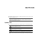
ProLiant ML530 Servers Maintenance and Service Guide Fourth Edition (September 2000) Part Number 122829-004 Spare Part Number 159306-001 Compaq Computer Corporation
Compaq ProLiant ML530 Servers Maintenance and Service Guide Notice © 2000 Compaq Computer Corporation Compaq, Deskpro, Compaq Insight Manager, ProLiant, ROMPaq, SmartStart, NetFlex, QuickFind, and the Compaq logo Registered in U.S. Patent and Trademark Office. Netelligent are trademarks and/or service marks of Compaq Information Technologies Group, L.P. Microsoft, Windows, and Windows NT are trademarks of Microsoft Corporation. Intel, Pentium, and Xeon are trademarks of Intel Corporation.
Contents About This Guide Symbols in Text.........................................................................................................vii Compaq Technician Notes .......................................................................................viii Where to Go for Additional Help ............................................................................... ix Telephone Numbers ............................................................................................
iv Compaq ProLiant ML530 Servers Maintenance and Service Guide Removal and Replacement Procedures continued Cable Routing Diagrams ........................................................................................2-26 System Fans-Power Cables .............................................................................2-27 SCSI Hard Drives and Removable Media Devices—Signal Cables ...............2-28 CD-ROM and Diskette Drives—Power and Signal Cables.............................
Contents Diagnostics and Troubleshooting continued Integrated Management Log...................................................................................3-51 Multiple Ways of Viewing the Log.................................................................3-51 Event List ........................................................................................................3-52 Event Messages ...............................................................................................
About This Guide This maintenance and service guide is a troubleshooting guide for reference when servicing Compaq ProLiant ML530 servers. IMPORTANT: The installation of options and the servicing of this product must be performed by individuals who are knowledgeable of the procedures, precautions, and hazards associated with equipment containing hazardous energy circuits. Symbols in Text These symbols may be found in the text of this guide. They have the following meanings.
viii Compaq ProLiant ML530 Servers Maintenance and Service Guide Compaq Technician Notes WARNING: Only authorized technicians trained by Compaq should attempt to repair this equipment. All troubleshooting and repair procedures are detailed to allow only subassembly/module-level repair. Because of the complexity of the individual boards and subassemblies, no one should attempt to make repairs at the component level or to make modifications to any printed wiring board.
About This Guide Where to Go for Additional Help In addition to this guide, the following information sources are available: ■ User documentation ■ Compaq Service Quick Reference Guide ■ Service training guides ■ Compaq service advisories and bulletins ■ Compaq QuickFind ■ Compaq Insight Manager ■ Compaq download facility data line: 281-518-1418 ■ Compaq website: http://www.compaq.
Chapter 1 Illustrated Parts List This chapter provides the illustrated parts breakdown and a spare parts list for Compaq ProLiant™ ML530 servers. To obtain information on names and part numbers of referenced spare parts, refer to Figure 1-1 and Table 1-1 for external components, and Figure 1-2 and Table 1-2 for system components. IMPORTANT: Use only 133-MHz front-side bus Pentium III Xeon processors with gold-colored heat sinks.
1-2 Compaq ProLiant ML530 Servers Maintenance and Service Guide External Components—Exploded View 2b 11 4 6 5 10 3 1 2a 9 20a 7 8 Figure 1-1.
Illustrated Parts List 1-3 External Components—Spare Parts List Table 1-1 External Components Spare Parts List Item Description Spare Part Number Chassis 1 Chassis, rack-mount 159316-001 2 Cover kit, rack-mount 167122-001 a) Rack-mount bezel b) Access panel 3 Power On/Standby switch with LEDs and cable 161659-001 Mass Storage Devices 4 Diskette drive, 1.
1-4 Compaq ProLiant ML530 Servers Maintenance and Service Guide System Components—Exploded View 18 21a 16 12 14 21b 19 15 17 20b 13 Figure 1-2.
Illustrated Parts List 1-5 System Components—Spare Parts List Table 1-2 System Components Spare Parts List Item Description Spare Part Number Boards 12 Power backplane board 159314-001 13 System board tray 159301-001 14 10/100 PCI network interface controller (NIC) 174831-001 Memory 15 Memory modules, 133-MHz, ECC SDRAM DIMM (maximum: 8 per unit) 64-MB SDRAM, 64 megabit memory module 159225-001 128-MB SDRAM, 64 megabit memory module 159226-001 128-MB SDRAM, 128 megabit memory module 1642
1-6 Compaq ProLiant ML530 Servers Maintenance and Service Guide Table 1-2 System Components Spare Parts List continued Item Description Spare Part Number Controllers 22 Smart Array 5300 Controller* 171383-001 23 32-MB memory module with battery backup* 171385-001 Cable Kits 24 SCSI cable kit* 159318-001 a) Internal SCSI cable b) External SCSI cable 25 Miscellaneous power cable kit* 159319-001 26 Miscellaneous signal cable kit* 159320-001 27 Real-time clock battery (4.
Chapter 2 Removal and Replacement Procedures This chapter provides subassembly/module-level removal and replacement procedures for Compaq ProLiant ML530 servers. After completing all the necessary removal and replacement procedures, run the Diagnostics program to verify that all components operate properly. WARNING: To reduce the risk of personal injury or damage to the equipment, heed all warnings and cautions throughout the “Removal and Replacement Procedures” chapter.
2-2 Compaq ProLiant ML530 Servers Maintenance and Service Guide Electrostatic Discharge Information A discharge of static electricity can damage static-sensitive devices or microcircuitry. Proper packaging and grounding techniques are necessary precautions to prevent damage. To prevent electrostatic damage, observe the following precautions: ■ Transport products in static-safe containers such as conductive tubes, bags, or boxes.
Removal and Replacement Procedures Symbols on Equipment Any surface or area of the equipment marked with these symbols indicates the presence of electric shock hazards. The enclosed area contains no operator-serviceable parts. WARNING: To reduce the risk of injury from electric shock hazards, do not open this enclosure. Any RJ-45 receptacle marked with these symbols indicates a Network Interface Connection.
2-4 Compaq ProLiant ML530 Servers Maintenance and Service Guide Preparation Procedures System power in Compaq ProLiant ML530 servers does not completely shut off with the front panel Power On/Standby switch. The switch toggles between on and standby, rather than on and off. The standby position removes power from most electronics and the drives, but portions of the power supply and some internal circuitry remain active.
Removal and Replacement Procedures Non-Hot-Pluggable Device Power must be removed from the server to remove or replace non-hot-pluggable devices. Non-hot-pluggable parts include the processors, all boards, DIMMs, and drive cages. See “Powering Down the Server” for complete power-down instructions.
2-6 Compaq ProLiant ML530 Servers Maintenance and Service Guide Rack Warnings WARNING: To reduce the risk of personal injury or damage to the equipment, be sure that: n The leveling jacks are extended to the floor. n The full weight of the rack rests on the leveling jacks. n The stabilizing feet are attached to the rack if it is a single-rack installation. n The racks are coupled in multiple-rack installations. n Only one component is extended at a time.
Removal and Replacement Procedures WARNING: To reduce the risk of personal injury, electric shock, or damage to the equipment: n The installation of internal options and routine maintenance and service of this product should be performed by individuals who are knowledgeable about the procedures, precautions, and hazards associated with equipment containing hazardous energy levels. n Allow the product to cool before removing covers and touching internal components.
2-8 Compaq ProLiant ML530 Servers Maintenance and Service Guide Tower Model Front Bezel Door To remove the tower model front bezel door: 1. Unlock and swing open the front bezel door completely. 2. Lift up the front bezel door and pull it away from the chassis . 2 1 Figure 2-1. Removing the tower model front bezel door Reverse steps 1 and 2 to replace the front bezel door.
Removal and Replacement Procedures Rack-Mount Bezel WARNING: To reduce the risk of personal injury or damage to the equipment, do not use the rack-mount bezel handles or system board tray handle to move Compaq ProLiant ML530 servers. To remove the rack-mount bezel: 1. Perform the preparation procedures. See “Hot-Pluggable Device” earlier in this chapter. 2. Loosen the access panel screws or remove the access panel. See “Access Panel” later in this chapter. 3.
2-10 Compaq ProLiant ML530 Servers Maintenance and Service Guide Access Panel WARNING: To reduce the risk of personal injury from hot surfaces, allow the internal system components to cool before touching them. CAUTION: Electrostatic discharge can damage electronic components. Be sure you are properly grounded before beginning any installation procedure. See “Electrostatic Discharge Information” earlier in this chapter.
Removal and Replacement Procedures Fans Compaq ProLiant ML530 servers ship standard with two hot-pluggable system fans (one CPU and one I/O) and three hot-pluggable drive fans. The two system fan baskets are designed to allow for a redundant hot-pluggable fan in each basket. Figure 2-4 and Table 2-1 illustrate the location of all fans in Compaq ProLiant ML530 servers, with the fan name and the description of what is cooled by each fan. NOTE: Fan speed will vary with the internal temperature of the server.
2-12 Compaq ProLiant ML530 Servers Maintenance and Service Guide Hot-Plug System Fans Compaq ProLiant ML530 servers have two system fan baskets, one for the I/O fan and one for the CPU fan. Each basket can hold a primary and a redundant hot-plug system fan. The hot-plug system fans cool the system board components (I/O fan) and the processors (CPU fan). CAUTION: Never remove both fans from one system fan basket while the server is powered up. Overheating and damage to hardware could result.
Removal and Replacement Procedures System Fan Basket Assembly The system fan basket assembly is comprised of two components: ■ Plastic system fan basket ■ Metal system fan basket-and-cable bracket The plastic basket holds the system fans in place. The metal bracket secures the basket and holds the fan cables in place. Before removing a system fan basket assembly, power must be removed from the server. Inadequate cooling will occur when both fans in a fan basket are removed.
2-14 Compaq ProLiant ML530 Servers Maintenance and Service Guide To remove the system fan basket-and-cable bracket: 1. Remove the system fan basket. See “To remove the system fan basket” earlier in this section. 2. Remove the four T-15 screws that secure the system fan basket-and-cable bracket to the chassis. 3. Slide the bracket toward the center of the chassis, then lift it away from the chassis . 1 2 Figure 2-7.
Removal and Replacement Procedures CPU Fan Air Baffle To remove the CPU fan air baffle: 1. Perform the preparation procedures. See “Hot-Pluggable Device” earlier in this chapter. 2. Remove the access panel. See “Access Panel” earlier in this chapter. 3. Unclip the external SCSI cable (if present) from the cable clips ➊ on the CPU fan air baffle. 4. Unsnap the two pins ➋ and loosen the thumbscrew on the CPU fan air baffle. 5. Lift the CPU fan air baffle away from the chassis . 2 2 3 4 1 Figure 2-8.
2-16 Compaq ProLiant ML530 Servers Maintenance and Service Guide Hard Drive Fan Air Baffle To remove the hard drive fan air baffle: 1. Perform the preparation procedures. See “Powering Down the Server” earlier in this chapter. 2. Remove the system fan basket assembly. See “System Fan Basket Assembly” earlier in this chapter. 3. Loosen the two thumbscrews ➊ on the hard drive fan air baffle. 4. Slide the baffle over the drive fans, then lift the hard drive fan air baffle out of the chassis ➋.
Removal and Replacement Procedures Hot-Plug Drive Fans Three hot-plug drive fans come standard with Compaq ProLiant ML530 servers. IMPORTANT: It is not necessary to power down the server to replace hot-plug devices such as power supplies, fans, or hard drives when they are not in active use. NOTE: The hot-plug drive fan looks similar to the fan used in the Compaq ProLiant 6400R server, but operates differently. The Compaq ProLiant 6400R fan is not compatible in Compaq ProLiant ML530 servers.
2-18 Compaq ProLiant ML530 Servers Maintenance and Service Guide Drive Fan Cable and Cable Bracket WARNING: To reduce the risk of personal injury or damage to the equipment, the installation of options other than hot-plug power devices should be performed only by individuals who are qualified in servicing computer equipment and trained to deal with products capable of producing hazardous energy levels. To remove the drive fan cable and cable bracket: 1. Perform the preparation procedures.
Removal and Replacement Procedures Removable Media and Mass Storage Devices Compaq ProLiant ML530 servers can house up to 16 mass storage devices, shown in Figure 2-12, including: ■ Preinstalled 3.5-inch 1.44-MB diskette drive ■ Preinstalled IDE CD-ROM drive ■ Two removable media devices ■ Two hot-plug drive cages containing twelve 1-inch LVD hot-plug drives (six drives each on two SCSI buses) 1 2 3 4 5 Figure 2-12.
2-20 Compaq ProLiant ML530 Servers Maintenance and Service Guide Hot-Plug SCSI Hard Drives CAUTION: Before removing or replacing a hot-plug SCSI hard drive, the affected drive must not be in use. See “LED Indicators, Hot-Plug SCSI Hard Drive” in Chapter 4 for more information. To remove a hot-plug SCSI hard drive: 1. Perform the preparation procedures. See “Hot-Pluggable Device” earlier in this chapter. 2. Open the front bezel door (tower model only). 3. Slide the release button ➊. 4.
Removal and Replacement Procedures Hard Drive Cage with Backplane Board CAUTION: If an active hard drive is replaced while the system is powered down, a POST error message (1786) will occur when the system is powered up. The following prompt will appear: PRESS TO BOOT THE SYSTEM AND REBUILD THE REPLACED DRIVE, OR PRESS TO BOOT THE SYSTEM WITHOUT REBUILDING THE DRIVE(S). Pressing F2 will cause permanent data loss to the logical hard drive.
2-22 Compaq ProLiant ML530 Servers Maintenance and Service Guide 6. Remove the four T-15 screws securing the hard drive cage to the chassis. 7. Slide the hard drive cage assembly out the front of the chassis. NOTE: To increase accessibility to the cables, remove the drive fans. See “Hot-Plug Drive Fans” earlier in this chapter. 2 1 1 Figure 2-14.
Removal and Replacement Procedures Removable Media Devices The removable media area contains two bays. To remove a device: 1. Perform the preparation procedures. See “Powering Down the Server” earlier in this chapter. 2. Remove the access panel. See “Access Panel” earlier in this chapter. 3. Disconnect all cabling from the removable media device. 4. Slide the green plastic locking lever on the outside of the removable media area to release the device. 5. Pull the device from the removable media area.
2-24 Compaq ProLiant ML530 Servers Maintenance and Service Guide CD-ROM Drive To remove the CD-ROM drive: 1. Perform the preparation procedures. See “Powering Down the Server” earlier in this chapter. 2. Remove the access panel. See “Access Panel” earlier in this chapter. 3. Remove the hard drive fan air baffle. See “Hard Drive Fan Air Baffle” earlier in this chapter. 4. Disconnect all cabling from the CD-ROM drive. The CD-ROM drive signal cable is color-coded orange. 5.
Removal and Replacement Procedures Diskette Drive To remove the diskette drive: 1. Perform the preparation procedures. See “Powering Down the Server” earlier in this chapter. 2. Remove the access panel. See “Access Panel” earlier in this chapter. 3. Disconnect all cabling from the diskette drive. The diskette drive signal cable is color-coded purple. 4. Loosen the thumbscrew on the side of the diskette drive. 5. Slide the diskette drive back , then lift it out of the chassis. 1 2 Figure 2-17.
2-26 Compaq ProLiant ML530 Servers Maintenance and Service Guide Cable Routing Diagrams The location and routing of each cable in Compaq ProLiant ML530 servers is shown in the following diagrams. For further information, refer to the Compaq ProLiant ML530 Setup and Installation Guide.
Removal and Replacement Procedures System Fans-Power Cables 1 2 Figure 2-18.
2-28 Compaq ProLiant ML530 Servers Maintenance and Service Guide SCSI Hard Drives and Removable Media Devices—Signal Cables 1 2 Figure 2-19. Signal cables for SCSI hard drives and removable media devices 2 Figure 2-20.
Removal and Replacement Procedures CD-ROM and Diskette Drives—Power and Signal Cables 2 1 Figure 2-21.
2-30 Compaq ProLiant ML530 Servers Maintenance and Service Guide System Board—Data Cable Figure 2-22. System data cable System Board—Power Cables 1 2 Figure 2-23.
Removal and Replacement Procedures SCSI Hard Drives and Removable Media Devices—Power Cables Figure 2-24. Power cables for SCSI hard drives and removable media devices Drive Fans—Power Cables Figure 2-25.
2-32 Compaq ProLiant ML530 Servers Maintenance and Service Guide System Board Tray WARNING: To reduce the risk of personal injury or damage to the equipment, do not use the system board tray handle to lift or move Compaq ProLiant ML530 servers. IMPORTANT: The system board tray is replaced as one unit. The system board does not have to be removed from the tray. To remove the system board tray: 1. Perform the preparation procedures. See “Powering Down the Server” earlier in this chapter. 2.
Removal and Replacement Procedures 4. Press the thumb latch adjacent to the system board tray handle to release the system board tray. Using the system board tray handle, pull the tray partially out of the chassis . 5. Disconnect and remove all cables from the system board and PCI expansion board. See “Cable Routing Diagrams” earlier in this chapter.
2-34 Compaq ProLiant ML530 Servers Maintenance and Service Guide System Board Components The system board is mounted to the inside of the tray. When the access panel and the CPU fan air baffle are removed, all the system board components are visible. 19 20 1 2 4 3 6 5 7 8 18 9 10 17 10 16 15 14 12 13 11 Figure 2-27.
Removal and Replacement Procedures PCI Retainer To remove the PCI retainer: 1. Perform the preparation procedures. See “Powering Down the Server” earlier in this chapter. NOTE: The PCI retainer is a shipping bracket and is not necessary for normal server operation. The PCI retainer may be removed using hot-pluggable device procedures, as long as the PCI expansion boards are not removed. 2. Remove the access panel. See “Access Panel” earlier in this chapter. 3. Loosen the thumbscrew . 4.
2-36 Compaq ProLiant ML530 Servers Maintenance and Service Guide PCI Expansion Boards Compaq ProLiant ML530 servers include eight PCI expansion slots, as shown in Figure 2-27. To remove an expansion board: 1. Perform the preparation procedures. See “Powering Down the Server” earlier in this chapter. 2. Remove the access panel. See “Access Panel” earlier in this chapter. 3. Remove the PCI retainer. See “PCI Retainer” earlier in this section.
Removal and Replacement Procedures PCI Bracket To remove the PCI bracket: 1. Remove all of the PCI expansion boards. See “PCI Expansion Boards” earlier in this section. 2. Loosen the two thumbscrews . 3. Slide the PCI bracket toward the system board, then out of the chassis . 1 1 2 Figure 2-30. Removing the PCI bracket Reverse steps 1 through 3 to replace the PCI bracket.
2-38 Compaq ProLiant ML530 Servers Maintenance and Service Guide Memory Modules Compaq ProLiant ML530 servers support from 64 MB to a maximum of 4 GB of synchronous DRAM (133-MHz, ECC SDRAM) DIMM memory. See Figure 2-31 for the SDRAM DIMM socket locations. Follow these guidelines, and the instructions in this section, when installing or replacing memory modules: ■ Install SDRAM DIMMs in the proper sockets. ■ Use only 64-, 128-, 256-, or 512-MB SDRAM DIMMs.
Removal and Replacement Procedures To remove an SDRAM DIMM: 1. Perform the preparation procedures. See “Powering Down the Server” earlier in this chapter. 2. Remove the access panel. See “Access Panel” earlier in this chapter. 3. Press both SDRAM DIMM socket latches outward. 4. Pull out the SDRAM DIMM . 1 2 1 Figure 2-32. Removing an SDRAM DIMM Reverse steps 1 through 4 to replace an SDRAM DIMM. IMPORTANT: A memory module can be installed one way only.
2-40 Compaq ProLiant ML530 Servers Maintenance and Service Guide Processors Compaq ProLiant ML530 servers support up to two processors. The primary processor is located closest to the edge of the system board. IMPORTANT: Use only 133-MHz front-side bus Pentium III Xeon processors with gold-colored heat sinks. Processors with other colored heat sinks will not function properly in Compaq ProLiant ML530 servers. To remove a processor: 1. Perform the preparation procedures.
Removal and Replacement Procedures Hot-Plug Power Supplies Compaq ProLiant ML530 servers use a hot-plug 450-watt power supply. Only one power supply is required on a system having a single six-bay SCSI hard drive cage. The power supply must be located in the primary bay. A second power supply is considered redundant for a single hard drive cage configuration, but necessary for a two hard drive cage configuration.
2-42 Compaq ProLiant ML530 Servers Maintenance and Service Guide To remove a hot-plug power supply: CAUTION: A power supply can only be replaced as a hot-pluggable device when the unit has redundancy. If there is only one power supply, or two power supplies with two hard drive cages, the unit must be powered down to replace the power supply. 1. Perform the preparation procedures. See “Hot-Pluggable Device” earlier in this chapter. 2. Unplug the power cord from the hot-plug power supply.
Removal and Replacement Procedures Power Supply Blanking Panel CAUTION: When the power supply is not being replaced, cover the opening with a power supply blanking panel to maintain proper airflow. To remove a power supply blanking panel: 1. Perform the preparation procedures. See “Hot-Pluggable Device” earlier in this chapter. 2. Remove the two T-15 screws securing the power supply blanking panel to the chassis. 3. Pull the power supply blanking panel away from the chassis. 1 2 Figure 2-36.
2-44 Compaq ProLiant ML530 Servers Maintenance and Service Guide Power Backplane Board To remove the power backplane board: 1. Perform the preparation procedures. See “Powering Down the Server” earlier in this chapter. 2. Remove the power supplies. See “Hot-Plug Power Supplies” earlier in this chapter. 3. Remove the access panel. See “Access Panel” earlier in this chapter. 4. Press the thumb latch adjacent to the system board tray handle to release the system board tray.
Removal and Replacement Procedures Power On/Standby Switch To remove the Power On/Standby switch and cable assembly: 1. Perform the preparation procedures. See “Powering Down the Server” earlier in this chapter. 2. Remove the access panel. See “Access Panel” earlier in this chapter. 3. Remove the hard drive fan air baffle. See “Hard Drive Fan Air Baffle” earlier in this chapter. 4. Disconnect the power switch cable from the power backplane board , and feed it through the cable grommet. 5.
Chapter 3 Diagnostics and Troubleshooting This chapter describes software and firmware diagnostic tools available for Compaq ProLiant ML530 servers.
3-2 Compaq ProLiant ML530 Servers Maintenance and Service Guide Diagnostic Tools Utility Overview The Compaq Diagnostic utilities were developed to assist in diagnosing problems, testing the hardware, and monitoring and managing Compaq server hardware. Table 3-1 Diagnostic Tools Tool Function Procedure Compaq Diagnostics A utility to assist testing and/or verifying operation of Compaq hardware. If problems are found, Compaq Diagnostics isolates failures down to a replaceable part, whenever possible.
Diagnostics and Troubleshooting Table 3-1 Diagnostic Tools continued Tool Function Procedure Array Diagnostics Utility (ADU) A Windows-based tool designed to run on all Compaq systems that support Compaq array controllers. Two main functions of ADU are to collect all possible information about the array controllers in the system and to generate a list of detected problems. Use the information provided in the “Array Diagnostics Utility” section later in this chapter.
3-4 Compaq ProLiant ML530 Servers Maintenance and Service Guide Default Configuration When the system is first turned on, the system ROM detects the unconfigured state of the hardware and provides default configuration settings for most devices. By providing this initialization, the system can run Diagnostics and other software applications before running the normal SmartStart and System Configuration programs.
Diagnostics and Troubleshooting Utilities Access The Compaq SmartStart and Support Software CD contains the SmartStart program and many of the Compaq utilities needed to maintain the system, including: ■ System Configuration Utility ■ Array Configuration Utility ■ Array Diagnostic Utility ■ ROMPaq Firmware Upgrade Utilities ■ Compaq Diagnostics CAUTION: Do not select the Erase Utility when running the SmartStart and Support Software CD. This will result in data loss to the entire system.
3-6 Compaq ProLiant ML530 Servers Maintenance and Service Guide Running the Utilities from Diskette ■ Run the utilities from their individual diskettes. If you have a utility diskette newer than the version on the SmartStart and Support Software CD, use the diskette. Always use the newest version of the utilities. ■ Create a diskette version of the utility from the SmartStart and Support Software CD. To create diskette versions of the utilities from the CD: 1.
Diagnostics and Troubleshooting Power-On Self-Test Power-On Self-Test (POST) is a series of diagnostic tests that run automatically on Compaq computers when the system is turned on.
3-8 Compaq ProLiant ML530 Servers Maintenance and Service Guide Table 3-2 POST Error Messages Error Code Audible Beeps Probable Source of Problem Recommended Action A Critical Error occurred prior to this power-up None A catastrophic system error, which caused the server to crash, has been logged. Run Diagnostics. Replace the failed assembly as indicated. Unsupported Processor Detected System Halted 1 long, 1 short Processor not supported by current system ROM.
Diagnostics and Troubleshooting 3-9 Table 3-2 POST Error Messages continued Error Code Audible Beeps Probable Source of Problem Recommended Action 174-Configuration/ Slot Mismatch Device Not Found None EISA or PCI board not found. Run the System Configuration Utility and correct. 175-Configuration/ Slot Mismatch Device Found None EISA or PCI board added, configuration not updated. Run the System Configuration Utility and correct.
3-10 Compaq ProLiant ML530 Servers Maintenance and Service Guide Table 3-2 POST Error Messages continued Error Code Audible Beeps Probable Source of Problem Recommended Action 219-Snoop Rules SRAM Failure. System Halted. None Catastrophic chipset failure. Call Compaq service provider. 220-Cache Accelerator Slot X Initialization Failed. System Halted. None Cache accelerator in slot X improperly installed or bad. Check cache accelerator installation and, if properly installed, replace.
Diagnostics and Troubleshooting 3-11 Table 3-2 POST Error Messages continued Error Code Audible Beeps Probable Source of Problem Recommended Action 1610-Temperature violation detected. Waiting for system to cool 2 short Ambient system temperature is too hot. Check fan and system environment. 1611-Fan failure detected 2 short Required fan is not installed or spinning. Check fans. 1611-I/O Fan (Fan X) failure detected 2 short I/O fan has failed. Replace the failed fan.
3-12 Compaq ProLiant ML530 Servers Maintenance and Service Guide Table 3-2 POST Error Messages continued Error Code Audible Beeps Probable Source of Problem Recommended Action 1622-Internal SCSI Jumper Board Not Installed None The system has detected that the array enabler board is not installed. Install the array enabler board. 1703-SCSI cable error detected. Terminated cable attached to output connector of SCSI backplane. System halted.
Diagnostics and Troubleshooting 3-13 Table 3-2 POST Error Messages continued Error Code Audible Beeps Probable Source of Problem Recommended Action 1721-Slot X Drive Array – Drive parameter tracking predicts an imminent failure. The following devices should be replaced when conditions permit. Do not replace drive unless all other drives in the array are online. Back up data before replacing drive(s) if using RAID 0. None Monitor and performance threshold exceeded condition.
3-14 Compaq ProLiant ML530 Servers Maintenance and Service Guide Table 3-2 POST Error Messages continued Error Code Audible Beeps Probable Source of Problem Recommended Action 1729-Slot 1 Drive Array – Disk Consistency Initialization in Progress – RAID 4/5 performance may be lower until auto-reliability monitoring has completed auto-background parity consistency initialization. None Initial RAID configuration in progress. Normal message following initialization, no action required.
Diagnostics and Troubleshooting 3-15 Table 3-2 POST Error Messages continued Error Code Audible Beeps Probable Source of Problem 1764-Slot X Drive Array – Capacity Expansion Process is temporarily disabled (followed by one of the following): ■ Expansion will resume when Array Accelerator has been reattached. ■ Expansion will resume when Array Accelerator has been replaced. ■ Expansion will resume when Array Accelerator RAM allocation is successful.
3-16 Compaq ProLiant ML530 Servers Maintenance and Service Guide Table 3-2 POST Error Messages continued Error Code Audible Beeps Probable Source of Problem Recommended Action 1772-Secondary Disk Port Address Assignment Conflict None Address assignment conflict. Internal and external hard drive controllers are both assigned to the secondary address. Run the System Configuration Utility and correct.
Diagnostics and Troubleshooting 3-17 Table 3-2 POST Error Messages continued Error Code 1777-Slot X Drive Array – ProLiant Drive Storage Enclosure Problem Detected (followed by one or more of the following): Audible Beeps None Probable Source of Problem Recommended Action Temperature violation detected. Cooling fan failure, internal temperature alert or open side panel Check cooling fan operation by placing your hand over the fan.
3-18 Compaq ProLiant ML530 Servers Maintenance and Service Guide Table 3-2 POST Error Messages continued Error Code Audible Beeps Probable Source of Problem Recommended Action 1782-Disk Controller Failure None Hard disk drive circuitry error Run Diagnostics. Replace failed assembly as indicated. 1783-Slot X Drive Array Controller Failure None ROM installation problem or array accelerator board problem.
Diagnostics and Troubleshooting 3-19 Table 3-2 POST Error Messages continued Error Code continue 1785-Drive Array not Configured (followed by one or more of the following): Audible Beeps None Probable Source of Problem Recommended Action Configuration error See actions below. Drive positions cannot be changed during Capacity Expansion. Run the Array Diagnostic Utility if previous positions are unknown. Then turn off system power and move the drives to their original positions.
3-20 Compaq ProLiant ML530 Servers Maintenance and Service Guide Table 3-2 POST Error Messages continued Error Code 1786-Slot 1 Drive Array Recovery Needed. The following SCSI drive(s) need Automatic Data Recovery: SCSI Port 1: SCSI ID 0 Audible Beeps None Probable Source of Problem Recommended Action System in Interim Data Recovery mode. Data has not yet been recovered. Press F1 to allow Automatic Data Recovery to begin.
Diagnostics and Troubleshooting 3-21 Table 3-2 POST Error Messages continued Error Code Audible Beeps * 1788-Incorrect Drive Replaced: Drive X Drive(s) were incorrectly replaced: Drive Y Select "F1" to continue – drive array will remain disabled. Select "F2" to reset configuration – all data will be lost. None 1789-Drive Not Responding, Physical Drive None Probable Source of Problem Recommended Action Drives are not installed in their original positions, so the drives have been disabled.
3-22 Compaq ProLiant ML530 Servers Maintenance and Service Guide Table 3-2 POST Error Messages continued Error Code Probable Source of Problem Recommended Action None While the system was in use, power was interrupted while data was in the array accelerator memory. The array accelerator batteries failed. Power was not restored within 8 to 10 days. Data in the array accelerator has been lost. Perform orderly system shutdowns to eliminate data remaining in the array accelerator.
Diagnostics and Troubleshooting 3-23 Table 3-2 POST Error Messages continued Error Code Audible Beeps Probable Source of Problem Recommended Action None Hard parity error while writing data to posted-writes memory. Enable array accelerator. 1799-Drive Array – Drive(s) Disabled due to Array Accelerator Data Loss. Select "F1" to continue with logical drives disabled. Select "F2" to accept data loss and to re-enable logical drives. None Volume failed due to loss of data in posted-writes memory.
3-24 Compaq ProLiant ML530 Servers Maintenance and Service Guide Diagnostics Software The Test Error Codes tables include all test error codes generated by Compaq products. Each code has a corresponding description and recommended actions. Each system generates only those codes that apply to its configuration and options. When you select Diagnostics and Utilities from the System Configuration Utility main menu, the utility prompts you to test, inspect, upgrade, and diagnose the server.
Diagnostics and Troubleshooting 100–199, Primary Processor Test Error Codes The 100 series of diagnostic error codes identifies failures with processor and system board functions. Table 3-3 Primary Processor Test Error Codes Error Code Description Recommended Action 101-xx CPU test failed. Replace the processor board and retest. 103-xx DMA page registers test failed. Replace the processor board and retest. 104-xx Interrupt controller master test failed.
3-26 Compaq ProLiant ML530 Servers Maintenance and Service Guide 200–299, Memory Test Error Codes The 200 series of diagnostic error codes identifies failures with the memory subsystem. Table 3-4 Memory Test Error Codes Error Code Description Recommended Action 200-xx Invalid memory configuration. Reinsert memory modules in correct location and retest. 201-xx Memory machine ID test failed. 1. Replace the system ROM and retest. 202-xx Memory system ROM checksum failed. 2.
Diagnostics and Troubleshooting 300–399, Keyboard Test Error Codes The 300 series of diagnostic error codes identifies failures with keyboard and system board functions. Table 3-5 Keyboard Test Error Codes Error Code Description Recommended Action 301-xx Keyboard short test, 8042 self-test failed. 1. 302-xx Keyboard long test failed. Check the keyboard connection. If disconnected, turn off the computer, connect the keyboard, turn on the power, and retest.
3-28 Compaq ProLiant ML530 Servers Maintenance and Service Guide 500–599, Video Display Unit Test Error Codes The 500 series of diagnostic error codes identifies failures with video or system board functions. Table 3-7 Video Display Unit Test Error Codes Error Code Description Recommended Action 501-xx Video controller test failed. 1. Replace the monitor and retest. 502-xx Video memory test failed. 2. Replace the Advanced VGA board and retest. 503-xx Video attribute test failed. 3.
Diagnostics and Troubleshooting 600–699, Diskette Drive Test Error Codes The 600 series of diagnostic error codes identifies failures with diskette, diskette drive, or system board functions. Table 3-8 Diskette Drive Test Error Codes Error Code Description Recommended Action 600-xx Diskette ID drive types test failed. 1. Replace the diskette and retest. 601-xx Diskette format failed. 2. 602-xx Diskette read test failed. Check and/or replace the diskette power and signal cables and retest. 3.
3-30 Compaq ProLiant ML530 Servers Maintenance and Service Guide 800–899, Video Board Test Error Codes The 800 series of diagnostic error codes identifies failures with video boards or system board functions. Table 3-9 Video Board Test Error Codes Error Code Description Recommended Action 802-xx Video memory test failed. 1. Replace monitor and retest. 824-xx Video text mode test failed. 2. Replace the Advanced VGA board and retest. 3. Replace the system board and retest.
Diagnostics and Troubleshooting 1200–1299, Modem Communications Test Error Codes The 1200 series of diagnostic error codes identifies failures with the modem. Table 3-11 Modem Communications Test Error Codes Error Code Description Recommended Action 1201-xx Modem internal loopback test failed. 1. Refer to the modem documentation for correct setup procedures and retest. 1202-xx Modem time-out test failed. 2. Check the modem line and retest. 1203-xx Modem external termination test failed. 3.
3-32 Compaq ProLiant ML530 Servers Maintenance and Service Guide 1700–1799, Hard Drive Test Error Codes The 1700 series of diagnostic error codes identifies failures with hard drives, hard drive controller boards, hard drive cabling, and system board functions. If the system uses a drive array controller, see the “Array Diagnostic Utility (ADU)” section. Table 3-12 Hard Drive Test Error Codes Error Code Description Recommended Action 1700-xx Hard drive ID drive types test failed. 1.
Diagnostics and Troubleshooting 1900–1999, Tape Drive Test Error Codes The 1900 series of diagnostic error codes identifies failures with tape cartridges, tape drives, tape drive cabling, adapter boards, or the system board assembly. Table 3-13 Tape Drive Test Error Codes Error Code Description Recommended Action 1900-xx Tape ID failed. 1. Replace the tape cartridge and retest. 1901-xx Tape servo write failed. 2. 1902-xx Tape format failed. Check and/or replace the signal cable and retest.
3-34 Compaq ProLiant ML530 Servers Maintenance and Service Guide Table 3-14 Advanced VGA Board Test Error Codes continued Error Code Description Recommended Action 2410-xx Video 640 × 200 mode test failed. 1. 2411-xx Video screen memory page test failed. Run the System Configuration Utility. 2. Replace the monitor and retest. 3. Replace the Advanced VGA board or other video board and retest. 4. Replace the system board and retest. 2412-xx Video gray scale test failed.
Diagnostics and Troubleshooting 6000–6099, Compaq NIC Boards Test Error Codes The 6000 series of diagnostic error codes identifies failures with 32-bit DualSpeed NetFlex-2/Token Ring Controllers. Table 3-15 Compaq Network Interface Controller Boards Test Error Codes Error Code Description Recommended Action 6000-xx Network card ID failed. 1. 6001-xx Network card setup failed. Check the controller installation in the PCI slot. 6002-xx Network card transmit failed. 2.
3-36 Compaq ProLiant ML530 Servers Maintenance and Service Guide 6500–6599, SCSI Hard Drive Test Error Codes The 6500 series of diagnostic error codes identifies failures with SCSI hard drives, SCSI hard drive controller boards, SCSI hard drive cabling, and system board functions. If the system uses a drive array controller, see the “Array Diagnostic Utility” section. Table 3-16 SCSI Hard Drive Test Error Codes Error Code Description Recommended Action 6500-xx SCSI disk ID drive types test failed.
Diagnostics and Troubleshooting 6700–6799, SCSI Tape Drive Test Error Codes The 6700 series of diagnostic error codes identifies failures with tape cartridges, tape drives, media changers, tape drive cabling, adapter boards, or the system board assembly. Table 3-18 SCSI Tape Drive Test Error Codes Error Code Description Recommended Action 6700-xx SCSI tape ID drive types test failed. 1. 6706-xx SCSI disk SA/media test failed. Run the System Configuration Utility and verify the drive type.
3-38 Compaq ProLiant ML530 Servers Maintenance and Service Guide Array Diagnostic Utility The Array Diagnostic Utility (ADU) is a Windows-based software tool designed to run on all Compaq servers that support Compaq array controllers and are configured with SmartStart 4.10 or later. The two main functions of ADU are to collect all possible information about array controllers in the system and to generate a list of detected problems.
Diagnostics and Troubleshooting Table 3-20 ADU Diagnostic Messages Message Description Recommended Action Accelerator board not detected Array controller did not detect a configured array accelerator board. Install the array accelerator board on the array controller. If an array accelerator board is already installed, check for proper seating on the array controller board.
3-40 Compaq ProLiant ML530 Servers Maintenance and Service Guide Table 3-20 ADU Diagnostic Messages continued Message Description Recommended Action Accelerator status: Excessive ECC errors detected in at least one cache line. As a result, at least one cache line is no longer in use. At least one line in the cache is no longer in use due to excessive ECC errors detected during use of the memory associated with that cache line. Replace the cache.
Diagnostics and Troubleshooting Table 3-20 ADU Diagnostic Messages continued Message Description Recommended Action Accelerator status: Valid data found at reset Valid data was found in posted write memory at reinitialization. Data will be flushed to disk. Not an error or data loss condition. No action required. Accelerator status: Warranty alert Catastrophic problem with array accelerator board. Refer to the other messages on Diagnostics screen for exact meaning of this message.
3-42 Compaq ProLiant ML530 Servers Maintenance and Service Guide Table 3-20 ADU Diagnostic Messages continued Message Description Recommended Action Controller is located in special “video” slot Controller is installed in slot for special video control signals. If controller is used in this slot, LED indicators on front panel may not function properly. Install the controller in a different slot and run the System Configuration Utility to configure the controller and nonvolatile RAM.
Diagnostics and Troubleshooting Table 3-20 ADU Diagnostic Messages continued Message Description Recommended Action Drive (bay) X is a replacement drive marked OK This drive has been replaced and marked OK by the firmware. This may occur if a drive has an intermittent failure (for example, if a drive has previously failed, then when ADU is run, the drive starts working again). Replace the drive. Drive (bay) X is failed The indicated physical drive has failed. Replace the drive.
3-44 Compaq ProLiant ML530 Servers Maintenance and Service Guide Table 3-20 ADU Diagnostic Messages continued Message Description Recommended Action Error occurred reading RIS copy from SCSI Port X Drive ID X An error occurred while ADU was trying to read the RIS from this drive. If there were multiple errors, this drive may need to be replaced. FYI: Drive (bay) X is third-party supplied The installed drive was not supplied by Compaq.
Diagnostics and Troubleshooting Table 3-20 ADU Diagnostic Messages continued Message Description Recommended Action Logical Drive X status = FAILED This status could be issued for several reasons. If this logical drive is configured for No Fault Tolerance and one or more drives fail, this status will occur. If mirroring is enabled and any two mirrored drives fail, this status will occur. If Data Guarding is enabled and two or more drives fail, this status will occur.
3-46 Compaq ProLiant ML530 Servers Maintenance and Service Guide Table 3-20 ADU Diagnostic Messages continued Message Description Recommended Action Loose cable detected – logical drives may be marked FAILED until corrected Controller unable to communicate with one or more physical drives, probably because of a cabling problem. Check all controllers and drive cable connections.
Diagnostics and Troubleshooting Table 3-20 ADU Diagnostic Messages continued Message Description Recommended Action ProLiant storage unit on SCSI bus X cabling error (bus disabled) This controller has internal and external connectors for the same SCSI bus. Therefore, the SCSI bus can only be cabled to a storage unit using the controller’s internal or external connector.
3-48 Compaq ProLiant ML530 Servers Maintenance and Service Guide Table 3-20 ADU Diagnostic Messages continued Message Description Recommended Action SCSI Port X Drive ID X is not stamped for monitoring Drive has not been stamped with monitor and performance features. Run the Array Configuration Utility (ACU). Changing the configuration and saving should cause ACU to stamp drive with monitor and performance features.
Diagnostics and Troubleshooting Table 3-20 ADU Diagnostic Messages continued Message Description Recommended Action System board is unable to identify which slots the controllers are in Slot indicator on motherboard is not working correctly. It appears to the firmware that both controllers are in the same slot. Make sure that controllers are fully seated. If the problem persists, this might indicate a controller problem or a system board problem. Follow these steps: 1.
3-50 Compaq ProLiant ML530 Servers Maintenance and Service Guide Table 3-20 ADU Diagnostic Messages continued Message Description Recommended Action Warning bit detected A monitor and performance threshold violation may have occurred. Status of a logical drive may not be OK. Check the other error messages on the diagnosis screen for an indication of the problem. Write memory error Data could not be written to cache memory.
Diagnostics and Troubleshooting Integrated Management Log The Compaq Integrated Management Log (IML) records system events and stores them in an easily viewable form. Each event is marked with a time-stamp with one-minute granularity. Events listed in the IML are categorized as one of four event severity levels: ■ Status—indicates that the message is informational only. ■ Repaired—indicates that corrective action has been taken. ■ Caution—indicates a nonfatal error condition.
3-52 Compaq ProLiant ML530 Servers Maintenance and Service Guide Printing the Event List NOTE: You can view the event list only from the Recovery/Integrated Management Log screen as described above in the “Viewing the Event List” section. 1. From the Compaq Insight Manager screen, select the appropriate server. 2. Select the Configuration button, then the Recovery button, then Print.
Diagnostics and Troubleshooting Event Messages Table 3-21 Event Messages Event Type Event Message Action Fan Failure System Fan Failure (Fan X, Location). Replace fan. Fan Inserted System Fan Inserted (Fan X, Location). None Fan Removed System Fan Removed (Fan X, Location). None Fans Not Redundant System Fans Not Redundant. Add fan. Overheat Condition System Overheating (Zone X, Location). Check fans. Corrected Memory Error Threshold passed (Slot X, Memory Module X).
3-54 Compaq ProLiant ML530 Servers Maintenance and Service Guide Table 3-21 Event Messages continued Event Type Event Message Action Power Supply Failure System Power Supply Failure (Power Supply X). Replace power supply. Power Supply Inserted System Power Supply Inserted (Power Supply X). None Power Supply Removed System Power Supply Removed (Power Supply X). None Power Supply Not Redundant System Power Supplies Not Redundant. Add power supply.
Diagnostics and Troubleshooting Rapid Error Recovery Compaq servers provide rapid recovery services for diagnosing and recovering from errors. These tools are available for local and remote diagnosis and recovery. Rapid recovery means fast identification and resolution of complex faults. The Rapid Recovery Engine and Insight Management Agents notify the system administrator when a failure occurs, ensuring that the server experiences minimal downtime.
3-56 Compaq ProLiant ML530 Servers Maintenance and Service Guide The available recovery features are: ■ Software Error Recovery—Automatically restarts the server after a software-induced server failure ■ Environmental Recovery—Allows the server to restart when temperature, fan, or AC power conditions return to normal Unattended Recovery For unattended recovery, ASR-2 performs the following actions: ■ Logs the error information to the IML ■ Resets the server ■ Pages you (if a modem is present and
Diagnostics and Troubleshooting Hardware Requirements To use this level of ASR-2 over a modem, you need the following: ■ A third-party PCI or external modem ■ System Configuration Utility and Diagnostics Utility installed on the system partition of the hard drive ■ ASR-2 configured to load Compaq Utilities after restart You can also run Compaq Utilities remotely over an IPX or IP network using the Network feature: ■ To use Compaq Utilities on an IPX network, you must have Compaq Insight Manager 2.
3-58 Compaq ProLiant ML530 Servers Maintenance and Service Guide Table 3-22 ASR-2 Features Features Definition Software error recovery If enabled, ASR-2 is activated if the OS hangs or has a crash that results in a lockup. Software error recovery timeout Determines how long the server waits to enable ASR-2 after an OS lockup. Standby recovery server option If enabled, ASR-2 activation initiates a switch to a standby recovery server.
Diagnostics and Troubleshooting Compaq Integrated Remote Console The standard Compaq Integrated Remote Console performs a wide range of configuration activities.
3-60 Compaq ProLiant ML530 Servers Maintenance and Service Guide The following ASR-2 flow chart shows you the sequence of events after a hardware or software error occurs: Hardware/Software error occurs. Error is recorded in the Critical Error Log or the Integrated Management Log, depending on the server configuration. Operating system halts normal operation. ASR timer expires. Server is reset.
Diagnostics and Troubleshooting Booting into Compaq Utilities When you enable ASR-2 to start into Compaq Utilities and a critical error occurs, the operating system-specific Health Driver logs the error information in the Critical Error Log or the IML and the ASR-2 feature restarts the server. When the system reinitializes, the system pages the designated administrator (if enabled), and starts Compaq Utilities from the hard drive. If Dial-In status is enabled, the modem is placed in auto-answer mode.
3-62 Compaq ProLiant ML530 Servers Maintenance and Service Guide Table 3-23 Compaq System Configuration Utility Pager Settings for Booting into Compaq Utilities continued Pager Data Setting Description Pager test Select to test pager setup Use this feature to test the current pager settings. Press Enter to dial the pager number, and the pager message (if present) displays. You must configure the computer before testing the pager, and the Pager Status must be set to Enabled.
Diagnostics and Troubleshooting Table 3-23 Compaq System Configuration Utility Pager Settings for Booting into Compaq Utilities continued Pager Data Setting Description Network host name CPQHOU Enter the network name of the server. Use underscores instead of spaces within the name, for example, Compaq_Server. If you are using IPX network access to the Compaq Utilities, this server name is used to advertise NVT host services.
3-64 Compaq ProLiant ML530 Servers Maintenance and Service Guide The System Configuration Utility setting should resemble the following when you enable ASR-2 to restart into the operating system: Table 3-24 OS Restart SCU Setting for ASR-2 Option Setting Serial interface COM1 Dial-in status Disabled Dial-out status Disabled Dial-out string 555-1234 Network status Disabled Network protocol IPX Network controller Compaq Network host name CPQHOU Network card slot Slot # Network frame typ
Diagnostics and Troubleshooting ASR-2 Integrated Management Log Messages The Integrated Management Log (IML) or Critical Error Log for Server Health Log records memory errors, as well as catastrophic hardware and software errors that cause the system to fail. This information helps you quickly identify and correct the problem, thus minimizing downtime. You can view the IML or Critical Error Log through Compaq Insight Manager.
3-66 Compaq ProLiant ML530 Servers Maintenance and Service Guide Table 3-25 ASR-2 IML or Critical Error Log Messages continued Message Description NMI – Automatic Server Recovery Timer Expiration The operating system has received notice of an impending ASR-2 timer expiration. NMI – Expansion Board Error A board on the expansion bus indicated an error condition, resulting in a server failure.
Diagnostics and Troubleshooting Revision History Table Some errors can be resolved by reviewing changes to the server configuration. The server has an Automatic Revision Tracking (ART) feature that helps you review recent changes to the server configuration. One ART feature is the Revision History Table, which contains the hardware version number of the system board and any other system boards providing ART-compatible revision information.
3-68 Compaq ProLiant ML530 Servers Maintenance and Service Guide Storage Fault Recovery Tracking This feature tracks over 12 failure-indication parameters, such as timeouts, spin-up, and self-test errors of SCSI drives. You can use these parameters to pinpoint failed storage subsystem components and to recover from controller or hard drive failure. Storage Automatic Reconstruction This feature automatically reconstructs data to an online spare or to a replaced drive if a drive fails.
Diagnostics and Troubleshooting Remote Service Features Compaq servers have management features that you can access through a modem or a network, as shown in Table 3-27. Table 3-27 Compaq Servers Remote Management Features Feature Description Service Session Provides remote access to all the utilities on the system partition, including Diagnostics utilities, Inspect, ROMPaq, Drive Array Advanced Diagnostics (DAAD), and the System Configuration Utility.
3-70 Compaq ProLiant ML530 Servers Maintenance and Service Guide ROMPaq Error Recovery Options From time to time, it may be necessary to upgrade the current system ROM. Some reasons for these errors include: ■ Customer requires ROM upgrade ■ Customer obtained new SmartStart CD-ROM ■ Customer requires server processors upgrade ■ Request from Compaq The process of upgrading the system ROM is referred to as flashing the ROM.
Diagnostics and Troubleshooting ROMPaq Disaster Recovery Use the following option with any server that does not have a valid ROM image. 1. Build a fresh ROMPaq diskette using the latest version for the server involved. NOTE: If the ROM is corrupted by a ROMPaq interruption, the initial ROMPaq attempt may have affected the contents of the original diskette. 2. Turn off the server. 3. Set configuration switches 1, 4, 5, and 6 on the system maintenance switch block to on to enable disaster mode.
3-72 Compaq ProLiant ML530 Servers Maintenance and Service Guide Compaq Insight Manager Compaq Insight Manager is the Compaq application for easily managing network devices. Compaq Insight Manager delivers intelligent monitoring and alerting as well as visual control of the servers. In Compaq servers, every hardware subsystem, such as disk storage, system memory, and system processor, has a strong set of management capabilities.
Diagnostics and Troubleshooting ■ SNMP standards—allow integration with other management products. ■ Flexible network conductivity—supports multiple transport protocols including IPX, TCP/IP and PPP to operator over LANs, WANs, and modems.
Chapter 4 Connectors, Switches, Jumpers, and LED Indicators This chapter lists connector, switch, jumper, and LED indicator information for Compaq ProLiant ML530 servers.
4-2 Compaq ProLiant ML530 Servers Maintenance and Service Guide Connectors This section contains information about service connectors, ports, and slots located on Compaq ProLiant ML530 servers. Rear Panel Connectors The rear panel connector locations for Compaq ProLiant ML530 servers are shown in Figure 4-1 and described in Figure 4-1. 8 9 7 1 2 3 4 5 6 Figure 4-1.
Connectors, Switches, Jumpers, and LED Indicators System Board Components The system board connector locations and descriptions for Compaq ProLiant ML530 servers are shown in Figure 4-2 and described in Table 4-2. 19 20 1 2 4 3 6 5 7 8 18 9 10 17 10 16 15 14 12 13 11 Figure 4-2.
4-4 Compaq ProLiant ML530 Servers Maintenance and Service Guide Switches This section contains information concerning all switches located on Compaq ProLiant ML530 servers. The system board has one DIP switch. The system configuration switch location is shown in Figure 4-3. 1 2 3 4 5 6 Figure 4-3. System board configuration switch location NOTE: The processor speed of Compaq ProLiant ML530 servers is determined by the system ROM during Power-On Self-Test (POST).
Connectors, Switches, Jumpers, and LED Indicators Jumpers and Headers Compaq ProLiant ML530 servers system board contains headers with jumpers for different purposes. The header locations are shown in Figure 4-4. 2 1 3 Figure 4-4. Jumper and header locations Battery Power Jumper The battery power header on the system board is shown in Figure 4-4. The battery power jumper is connected to the battery power header and delivers battery power to CMOS and NVRAM.
4-6 Compaq ProLiant ML530 Servers Maintenance and Service Guide LED Indicators This section contains information about status and diagnostic LED locations and conditions on Compaq ProLiant ML530 servers. Front Panel Status Four status LED indicators are located on the front panel near the power switch. Figure 4-5 shows the location of the LEDs. Table 4-4 identifies the LEDs and describes the condition of the device. 1 2 3 4 Figure 4-5.
Connectors, Switches, Jumpers, and LED Indicators Power The power status LED on the front panel indicates whether the unit has full power (green) or is in standby mode (amber). A flashing amber light indicates a temperature event that causes the unit to shut down for approximately 15 seconds. An unlit LED generally indicates that the unit does not have power. Critical System The critical system status LED on the front panel indicates the condition of both the memory modules (DIMMs) and processors.
4-8 Compaq ProLiant ML530 Servers Maintenance and Service Guide Memory Module The memory module (DIMM) diagnostic LED, located adjacent to each memory module socket, indicates the condition of each DIMM. If the front panel critical system status LED is amber, check the individual DIMM diagnostic LEDs to determine which DIMM has failed. To view the diagnostic LEDs, remove the access panel of the server. See “Access Panel” in Chapter 2.
Connectors, Switches, Jumpers, and LED Indicators Hot-Plug Fan The hot-plug fan diagnostic LEDs indicate the condition of each fan in Compaq ProLiant ML530 servers. If the front panel fan status LED is amber, check the individual fan diagnostic LEDs to determine which fan has failed. The hot-plug fan diagnostic LEDs can be viewed by removing the access panel of the server. To remove the access panel, see “Access Panel” in Chapter 2. Figure 4-7 shows the location of the hot-plug fan diagnostic LEDs.
4-10 Compaq ProLiant ML530 Servers Maintenance and Service Guide Hot-Plug Power Supply The hot-plug power supply diagnostic LEDs indicate the condition of each hot-plug power supply. If the front panel power supply status LED is amber, check the individual power supply diagnostic LEDs to determine which power supply has failed. View the diagnostic LEDs from the rear of the server. The power supply diagnostic LEDs and their functions for Compaq ProLiant ML530 servers are shown in Figure 4-8 and Table 4-8.
Connectors, Switches, Jumpers, and LED Indicators Hot-Plug SCSI Hard Drive Each hot-plug SCSI hard drive LED indicates the operational status of the hard drive. The hot-plug hard drive LED location, function, and replacement condition for Compaq ProLiant ML530 servers is shown in Figure 4-9 and described in Table 4-9. Refer to the Compaq ProLiant ML530 Troubleshooting Guide for further information. 1 2 3 Figure 4-9.
4-12 Compaq ProLiant ML530 Servers Maintenance and Service Guide RJ-45 Network Connector The RJ-45 network connector status LEDs are located on the rear of Compaq ProLiant ML530 server. These LEDs indicate the condition of the server’s network connection. 1 2 Figure 4-10.
Connectors, Switches, Jumpers, and LED Indicators CD-ROM Drive The CD-ROM drive status LED for Compaq ProLiant ML530 servers is located on the front of the CD-ROM drive near the volume control. The LED is green when the CD-ROM drive is in operation. 1 Figure 4-11. CD-ROM drive status LED Diskette Drive The diskette drive status LED for Compaq ProLiant ML530 servers is located on the front of the diskette drive near the bottom left of the diskette drive slot.
Chapter 5 Physical and Operating Specifications This chapter provides operating and performance specifications for Compaq ProLiant ML530 servers and optional hardware. Specifications covered in this chapter are: ■ System Unit ■ Hot-Plug Power Supply ■ SDRAM Dual Inline Memory Modules ■ 1.
5-2 Compaq ProLiant ML530 Servers Maintenance and Service Guide System Unit Table 5-1 System Unit Specifications Dimensions Height 51.5 cm (20.3 inch) Depth 69.7 cm (27.5 inch) Width 32.6 cm (12.9 inch) Weight 45 kg, minimum (100 lb, minimum) International input requirements Rated input voltage 200 to 240 V Rated input frequency 50 to 60 Hz Rated input current 3.8 A U.S. input requirements Rated input voltage 100 to 120 V Rated input frequency 50 to 60 Hz Rated input current 7.
Physical and Operating Specifications Hot-Plug Power Supply Table 5-2 Hot-Plug Power Supply Specifications International input specifications Nominal line voltage 200 to 240 VAC Range input line 180 to 270 VAC Frequency range 47 to 63 Hz Power factor 0.95 Input current 3.8 A at 200 VAC Inrush current (cold start) <150 A at 132 VAC Holdup time 20 ms from zero crossing at 240 VAC U.S.
5-4 Compaq ProLiant ML530 Servers Maintenance and Service Guide SDRAM Dual Inline Memory Modules CAUTION: Use only SDRAM DIMMs of the same size, speed, and manufacturer. SDRAM DIMMs from other sources may adversely affect data integrity. The Power-On Self-Test (POST) will warn of nonsupported SDRAM DIMMs.
Physical and Operating Specifications IDE CD-ROM Drive Table 5-5 2 32X Max IDE CD-ROM Drive Specifications Dimensions Height 4.29 cm (1.9 inch) Width 15 cm (5.9 inch) Depth 20.8 cm (8.1 inch) Weight 950 g (2.
5-6 Compaq ProLiant ML530 Servers Maintenance and Service Guide Integrated Dual-Channel Wide Ultra2 SCSI Controller Table 5-6 Integrated Dual-Channel Wide Ultra2 SCSI Controller Specifications Drives supported Up to 12 Wide Ultra2 devices per channel Data transfer method 64-bit, 33-MHz PCI SCSI channel transfer rate per channel 80 MB/s Maximum transfer rate per PCI bus 133 MB/s SCSI termination Active termination SCSI connectors Channel A 1 internal Channel B/external 1 internal/external
Physical and Operating Specifications Hot-Plug Hard Drives Table 5-7 Hot-Plug Hard Drive Specifications 9.1 GB 9.1 GB 9.1 GB 18.2 GB 18.2 GB 18.2 GB Rotational speed (rpm) 7,200 10,000 10,000 7,200 10,000 10,000 Logical capacity (MB) 9100 9100 9100 18209 18209 18210 Inches 1.0 1.0 1.0 1.0 1.0 1.0 Centimeters 2.5 2.5 2.5 2.5 2.5 2.5 Inches 3.5 3.5 3.5 3.5 3.5 3.5 Centimeters 8.9 8.9 8.9 8.9 8.9 8.
Index Symbols and Numbers 10/100 PCI Network Interface Controller See NIC A AC circuit overload warnings 2-7 AC power connector, identified 4-2 access panel part number 1-3, 1-6 removing 2-10 removing, illustrated 2-10 replacing 2-10 accessing system board components 2-34 ADU See Array Diagnostics Utility air baffle CPU fan part number 1-5 removing 2-15 removing, illustrated 2-15 replacing 2-15 hard drive fan part number 1-5 removing 2-16 removing, illustrated 2-16 replacing 2-16 Array Configuration Utili
2 Compaq ProLiant ML530 Servers Maintenance and Service Guide network host name, restart setting 3-64 network IP address, restart setting 3-64 network IP net mask, restart setting 3-64 network IP router address, restart setting 3-64 network protocol, restart setting 3-64 network status, restart setting 3-64 OS Restart SCU Setting, table 3-64 paging administrator 3-55 security 3-64 serial interface, restart setting 3-64 software error recovery 3-58 recovery boot option 3-58 recovery timeout 3-58 standby re
Index data transfer rate 5-5 depth 5-5 height 5-5 laser parameters 5-5 LEDs, viewing 4-13 location 2-19 part number 1-3 power and signal cables identified 2-29 removing 2-24 removing, illustrated 2-24 replacing 2-24 signal cable connector, identified 2-34, 4-3 startup time 5-5 status LED, illustrated 4-13 stop time 5-5 test error codes 3-36 warnings 2-3 weight 5-5 width 5-5 chassis, part number 1-3, 1-6 Client Management, defined 3-72 communication parameters, setting 3-61 Compaq Diagnostics accessing 3-2
4 Compaq ProLiant ML530 Servers Maintenance and Service Guide SCSI hard drive 3-36 SCSI tape drive 3-37 SCSI/IDE CD-ROM drive 3-36 serial port 3-30 tape drive 3-33, 3-37 VGA board 3-33 video board 3-30 video display unit 3-28 when to run 3-7 dial-in status, setting 3-62 dial-out status, setting 3-62 dial-out string, setting 3-62 DIMMs See memory Disk-Based Diagnostics accessing remotely 3-69 diskette boot feature setting 4-4 diskette drive disabling 3-71 LEDs, viewing 4-13 location 2-19 part number 1-3 re
Index Abnormal Program Termination 3-65 ASR-2 detected by ROM 3-65 ASR-2 Test Event 3-65 Automatic Server Recovery Base Memory Parity Error 3-65 Extended Memory Parity Error 3-65 Memory Parity Error 3-65 Reset Limit Reached 3-65 Battery Failing 3-65 Caution, Temperature Exceeded 3-65 Diagnostic Error 3-65 Error Detected On Boot Up 3-65 NMI Automatic Server Recovery Timer Expiration 3-66 Expansion Board Error 3-66 Expansion Bus Master Time-Out 3-66 Expansion Bus Slave Time-Out 3-66 Fail-Safe Timer Expiratio
6 Compaq ProLiant ML530 Servers Maintenance and Service Guide is failed 3-43 is undergoing drive recovery 3-43 needs replacing 3-43 upload code not readable 3-43 was inadvertently replaced 3-43 Drive Monitoring features are unobtainable 3-43 Drive Monitoring is NOT enabled 3-43 Drive time-out occurred on physical drive bay X 3-43 Drive X indicates position Y 3-43 Duplicate write memory error 3-43 Error occurred reading RIS copy from SCSI Port X 3-44 Fatal ROM Error 3-8 FYI, Drive (bay) X is non-Compaq sup
Index power supply failure 3-54 power supply inserted 3-54 power supply not redundant 3-54 power supply removed 3-54 processor Correctable Error Threshold exceeded 3-53 Host Bus Error 3-53 Uncorrectable Error 3-53 events log description 3-3 viewing 3-3 exploded view external components 1-2 system components 1-4 external battery header function 4-5 identified 2-34, 4-3 external components, exploded view 1-2 external SCSI slot, identified 4-2 F fans cable connectors, identified 2-34, 4-3 diagnostic LEDs ill
8 Compaq ProLiant ML530 Servers Maintenance and Service Guide technical support telephone numbers ix hot surfaces warnings 2-7, 2-10 hot-plug devices, removing 2-4 hot-plug drive cage duplex configuration 2-19 simplex configuration 2-19 hot-plug hard drive fans removing 2-17 removing, illustrated 2-17 replacing 2-17 hot-plug power supply See power supply hot-plug SCSI hard drives removing 2-20 hot-plug system fan removing 2-12 replacing 2-12 I I/O board configuration switch illustrated 4-4 settings 4-4 I
Index M maintenance and service guide, part number 1-6 maintenance switch setting 4-4 mass storage devices location 2-19 maximum number supported 2-19 memory diagnostic LED, viewing 4-8 installation guidelines 2-38 installation order 2-38 maximum supported 2-38 part numbers 1-5 removing 2-39 removing, illustrated 2-39 replacing 2-38, 2-39 socket locations, illustrated 2-38 sockets, identified 2-34, 4-3 specifications 5-4 speed 5-4 standard 2-38 test error codes 3-26 upgrade requirements 5-4 memory errors r
10 Compaq ProLiant ML530 Servers Maintenance and Service Guide hard drive blank 1-3 hard drive cage blanking panel 1-3 hard drive cage w/backplane board 1-3 hard drives 1-3 keyboard 1-6 maintenance and service guide 1-6 memory modules 1-5 miscellaneous hardware kit 1-5 plastics kit 1-5 power cable kit 1-6 signal cable kit 1-6 NIC 1-5 power backplane board 1-5 Power On/Standby switch 1-3 power supply 1-3 power supply blanking panel 1-3 processors 1-5 rack-mount bezel 1-3 real-time clock battery 1-6 removab
Index power-on-password, defeating 4-4 prefailure alerting 3-73 preparation removal and replacement procedures 2-4 primary CPU fan identified 2-11 primary I/O fan identified 2-11 processor diagnostic LED, viewing 4-8 locating primary 2-40 number supported 2-40 removing 2-40 removing, illustrated 2-40 replacing 2-40 slots, identified 2-34, 4-3 test error codes 3-25 processors part numbers 1-5 R rack cover kit, part number 1-3 rack warnings equipment damage 2-6 moving 2-6 personal injury 2-6 rack loading 2-
12 Compaq ProLiant ML530 Servers Maintenance and Service Guide drive fan cable and cable bracket 2-18 hard drive cage w/backplane board 2-22 hard drive fan air baffle 2-16 hot-plug hard drive fans 2-17 memory 2-38, 2-39 PCI bracket 2-37 PCI expansion board 2-36 PCI retainer 2-35 power backplane board 2-44 Power On/Standby switch 2-45 power supply 2-41, 2-42 power supply blanking panel 2-43 processor 2-40 removable media devices 2-23 system board 2-33 system fan cable 2-14 resource conflict, resolving 3-3
Index height 5-4 read/write heads 5-4 rotation 5-4 size 5-4 transfer rate 5-4 hard drives 5-7 height 5-7 interface 5-7 operating temperature 5-7 physical configuration 5-7 seek time 5-7 transfer rate 5-7 width 5-7 memory size 5-4 operating 5-1 optional hardware 5-1 performance 5-1 physical 5-1 power supply 5-3 international input 5-3 minimum load 5-3 operating temperatures 5-3 U.S.
14 Compaq ProLiant ML530 Servers Maintenance and Service Guide part number 1-5 removing 2-13 removing, illustrated 2-13 replacing 2-13 system fan basket-and-cable bracket, part number 1-5 system fan cable bracket removing 2-14 system fans cable, removing 2-14 cable, replacing 2-14 part number 1-5 removing 2-12 removing, illustrated 2-12 replacing 2-12 system fans power cables illustrated 2-27 system partition, accessing utilities from 3-5 system unit, specifications 5-2 T tape drives, test error codes 3-
Index Health Driver 3-59 Inspect accessing 3-2, 3-24 description 3-2, 3-4 printing Inspect listing 3-4 running 3-4 Integrated Management Log, description 3-3 OS IML Viewer, defined 3-52 Remote Utilities, accessing 3-24 ROMPaq Firmware Upgrade, accessing 3-5 running from SmartStart and Support Software CD 3-6 Server Restart, accessing remotely 3-69 starting from ASR-2 3-61 System Configuration accessing 3-5 booting from pager 3-61 description 3-3 executing 3-6 running 3-3 Test Computer, accessing 3-24 Upgra