
ProLiant ML530 Servers Maintenance and Service Guide


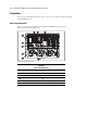
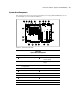


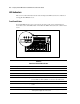

Table Of Contents
- Compaq ProLiant ML530 Servers Maintenance and Service Guide
- Notice Page
- Table of Contents
- About This Guide
- Chapter 1: Illustrated Parts List
- Chapter 2: Removal and Replacement Procedures
- Electrostatic Discharge Information
- Symbols on Equipment
- Preparation Procedures
- Tower Model Front Bezel Door
- Rack Mount Bezel
- Access Panel
- Fans
- Removable Media and Mass Storage Devices
- Cable Routing Diagrams
- System Board Tray
- System Board Components
- Hot Plug Power Supplies
- Power Backplane Board
- Power On/Standby Switch
- Chapter 3: Diagnostics and Troubleshooting
- Diagnostic Tools Utility Overview
- Default Configuration
- Utilities Access
- Power On Self Test
- Diagnostics Software
- Steps for Diagnostics
- 100–199, Primary Processor Test Error Codes
- 200–299, Memory Test Error Codes
- 300–399, Keyboard Test Error Codes
- 400–499, Parallel Printer Test Error Codes
- 500–599, Video Display Unit Test Error Codes
- 600–699, Diskette Drive Test Error Codes
- 800–899, Video Board Test Error Codes
- 1100–1199, Serial Test Error Codes
- 1200–1299, Modem Communications Test Error Codes
- 1700–1799, Hard Drive Test Error Codes
- 1900–1999, Tape Drive Test Error Codes
- 2400–2499, Advanced VGA Board Test Error Codes
- 6000–6099, Compaq NIC Boards Test Error Codes
- 6500–6599, SCSI Hard Drive Test Error Codes
- 6700–6799, SCSI Tape Drive Test Error Codes
- 8600–8699, Pointing Device Interface Test Error Codes
- Array Diagnostic Utility
- Integrated Management Log
- Rapid Error Recovery
- Remote Service Features
- ROMPaq Error Recovery Options
- Compaq Insight Manager
- Chapter 4: Connectors, Switches, Jumpers, and LED Indicators
- Chapter 5: Physical and Operating Specifications
- Index
Connectors, Switches, Jumpers, and LED Indicators 4-3
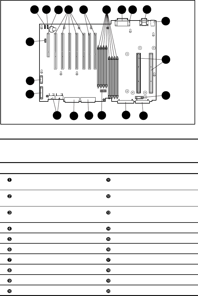
System Board Components
The system board connector locations and descriptions for Compaq ProLiant ML530 servers are
shown in Figure 4-2 and described in Table 4-2.
1
6
5
4
14
15
16
3
7
8
9
12
11
10
17
10
2
18
13
19
20
Figure 4-2. System board components
Table 4-2
System Board Components
Item Description Item Description
32-bit, 33-MHz primary PCI bus Diskette drive signal cable
connector (purple)
64-bit, 33-MHz, tertiary PCI bus IDE CD-ROM signal cable connector
(orange)
64-bit, 66-MHz, 3-volt only
secondary PCI bus
Configuration switch
2 sets of 4 DIMM memory sockets SCSI channel A connector (blue)
Parallel port SCSI channel B connector (yellow)
Video port Power connectors
Serial ports System data connector
Keyboard/mouse interface Remote power switch header
Processor slots Battery power header
Fan cable connectors (2 locations) External battery header