
ProLiant ML530 Servers Maintenance and Service Guide


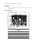
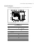


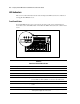

Table Of Contents
- Compaq ProLiant ML530 Servers Maintenance and Service Guide
- Notice Page
- Table of Contents
- About This Guide
- Chapter 1: Illustrated Parts List
- Chapter 2: Removal and Replacement Procedures
- Electrostatic Discharge Information
- Symbols on Equipment
- Preparation Procedures
- Tower Model Front Bezel Door
- Rack Mount Bezel
- Access Panel
- Fans
- Removable Media and Mass Storage Devices
- Cable Routing Diagrams
- System Board Tray
- System Board Components
- Hot Plug Power Supplies
- Power Backplane Board
- Power On/Standby Switch
- Chapter 3: Diagnostics and Troubleshooting
- Diagnostic Tools Utility Overview
- Default Configuration
- Utilities Access
- Power On Self Test
- Diagnostics Software
- Steps for Diagnostics
- 100–199, Primary Processor Test Error Codes
- 200–299, Memory Test Error Codes
- 300–399, Keyboard Test Error Codes
- 400–499, Parallel Printer Test Error Codes
- 500–599, Video Display Unit Test Error Codes
- 600–699, Diskette Drive Test Error Codes
- 800–899, Video Board Test Error Codes
- 1100–1199, Serial Test Error Codes
- 1200–1299, Modem Communications Test Error Codes
- 1700–1799, Hard Drive Test Error Codes
- 1900–1999, Tape Drive Test Error Codes
- 2400–2499, Advanced VGA Board Test Error Codes
- 6000–6099, Compaq NIC Boards Test Error Codes
- 6500–6599, SCSI Hard Drive Test Error Codes
- 6700–6799, SCSI Tape Drive Test Error Codes
- 8600–8699, Pointing Device Interface Test Error Codes
- Array Diagnostic Utility
- Integrated Management Log
- Rapid Error Recovery
- Remote Service Features
- ROMPaq Error Recovery Options
- Compaq Insight Manager
- Chapter 4: Connectors, Switches, Jumpers, and LED Indicators
- Chapter 5: Physical and Operating Specifications
- Index
Connectors, Switches, Jumpers, and LED Indicators 4-5
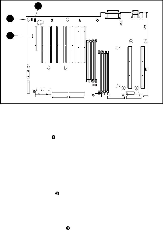
Jumpers and Headers
Compaq ProLiant ML530 servers system board contains headers with jumpers for different
purposes. The header locations are shown in Figure 4-4.
1
2
3
Figure 4-4. Jumper and header locations
Battery Power Jumper
The battery power header on the system board is shown in Figure 4-4. The battery power
jumper is connected to the battery power header and delivers battery power to CMOS and
NVRAM. The default setting for the battery power jumper is across pins 1 and 2.
To erase an invalid system configuration, jumper across pins 2 and 3 to ground the connection.
This jumper setting clears CMOS and NVRAM within two minutes.
External Battery Header
The external battery header on the system board is shown in Figure 4-4. The external battery
header is the connector used to attach an external battery to the unit.
Remote Power Switch Header
The remote power switch header on the system board is shown in Figure 4-4. The remote
power switch header connects an optional Remote Insight Lights-Out Edition board to the
system board of the Compaq ProLiant ML530 server.