
ProLiant ML530 Servers Maintenance and Service Guide


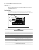

Table Of Contents
- Compaq ProLiant ML530 Servers Maintenance and Service Guide
- Notice Page
- Table of Contents
- About This Guide
- Chapter 1: Illustrated Parts List
- Chapter 2: Removal and Replacement Procedures
- Electrostatic Discharge Information
- Symbols on Equipment
- Preparation Procedures
- Tower Model Front Bezel Door
- Rack Mount Bezel
- Access Panel
- Fans
- Removable Media and Mass Storage Devices
- Cable Routing Diagrams
- System Board Tray
- System Board Components
- Hot Plug Power Supplies
- Power Backplane Board
- Power On/Standby Switch
- Chapter 3: Diagnostics and Troubleshooting
- Diagnostic Tools Utility Overview
- Default Configuration
- Utilities Access
- Power On Self Test
- Diagnostics Software
- Steps for Diagnostics
- 100–199, Primary Processor Test Error Codes
- 200–299, Memory Test Error Codes
- 300–399, Keyboard Test Error Codes
- 400–499, Parallel Printer Test Error Codes
- 500–599, Video Display Unit Test Error Codes
- 600–699, Diskette Drive Test Error Codes
- 800–899, Video Board Test Error Codes
- 1100–1199, Serial Test Error Codes
- 1200–1299, Modem Communications Test Error Codes
- 1700–1799, Hard Drive Test Error Codes
- 1900–1999, Tape Drive Test Error Codes
- 2400–2499, Advanced VGA Board Test Error Codes
- 6000–6099, Compaq NIC Boards Test Error Codes
- 6500–6599, SCSI Hard Drive Test Error Codes
- 6700–6799, SCSI Tape Drive Test Error Codes
- 8600–8699, Pointing Device Interface Test Error Codes
- Array Diagnostic Utility
- Integrated Management Log
- Rapid Error Recovery
- Remote Service Features
- ROMPaq Error Recovery Options
- Compaq Insight Manager
- Chapter 4: Connectors, Switches, Jumpers, and LED Indicators
- Chapter 5: Physical and Operating Specifications
- Index
4-6 Compaq ProLiant ML530 Servers Maintenance and Service Guide
LED Indicators
This section contains information about status and diagnostic LED locations and conditions on
Compaq ProLiant ML530 servers.
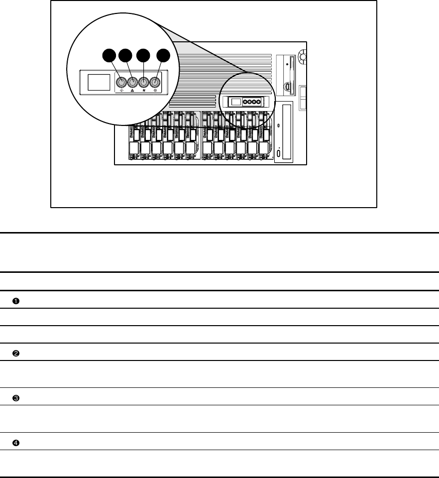
Front Panel Status
Four status LED indicators are located on the front panel near the power switch. Figure 4-5
shows the location of the LEDs. Table 4-4 identifies the LEDs and describes the condition of the
device.
1
3 4
2
Figure 4-5. Front panel status LED indicators
Table 4-4
Front Panel Status LED Indicators
Item Description Status Condition
Power Green System power is on.
Amber System power is in standby.
Amber (flashing) Temporary shutdown occurred due to thermal event.
Critical system Green All memory modules (DIMMs) and processors are operational.
Amber (flashing) One or more DIMMs or processors have failed—check system board DIMM or
processor LEDs. See “Memory Module” or “Processor” later in this section.
Fans Green All fans are operational.
Amber (flashing) One or more fans have failed—check fan LEDs. See “Hot-Plug Fan” later in this
section.
Power supplies Green All power supplies are operational.
Amber (flashing) One or more power supplies have failed—check power supply LEDs. See
“Hot-Plug Power Supply” later in this section.