
ProLiant ML530 Servers Maintenance and Service Guide

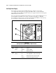

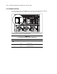


Table Of Contents
- Compaq ProLiant ML530 Servers Maintenance and Service Guide
- Notice Page
- Table of Contents
- About This Guide
- Chapter 1: Illustrated Parts List
- Chapter 2: Removal and Replacement Procedures
- Electrostatic Discharge Information
- Symbols on Equipment
- Preparation Procedures
- Tower Model Front Bezel Door
- Rack Mount Bezel
- Access Panel
- Fans
- Removable Media and Mass Storage Devices
- Cable Routing Diagrams
- System Board Tray
- System Board Components
- Hot Plug Power Supplies
- Power Backplane Board
- Power On/Standby Switch
- Chapter 3: Diagnostics and Troubleshooting
- Diagnostic Tools Utility Overview
- Default Configuration
- Utilities Access
- Power On Self Test
- Diagnostics Software
- Steps for Diagnostics
- 100–199, Primary Processor Test Error Codes
- 200–299, Memory Test Error Codes
- 300–399, Keyboard Test Error Codes
- 400–499, Parallel Printer Test Error Codes
- 500–599, Video Display Unit Test Error Codes
- 600–699, Diskette Drive Test Error Codes
- 800–899, Video Board Test Error Codes
- 1100–1199, Serial Test Error Codes
- 1200–1299, Modem Communications Test Error Codes
- 1700–1799, Hard Drive Test Error Codes
- 1900–1999, Tape Drive Test Error Codes
- 2400–2499, Advanced VGA Board Test Error Codes
- 6000–6099, Compaq NIC Boards Test Error Codes
- 6500–6599, SCSI Hard Drive Test Error Codes
- 6700–6799, SCSI Tape Drive Test Error Codes
- 8600–8699, Pointing Device Interface Test Error Codes
- Array Diagnostic Utility
- Integrated Management Log
- Rapid Error Recovery
- Remote Service Features
- ROMPaq Error Recovery Options
- Compaq Insight Manager
- Chapter 4: Connectors, Switches, Jumpers, and LED Indicators
- Chapter 5: Physical and Operating Specifications
- Index
Connectors, Switches, Jumpers, and LED Indicators 4-9
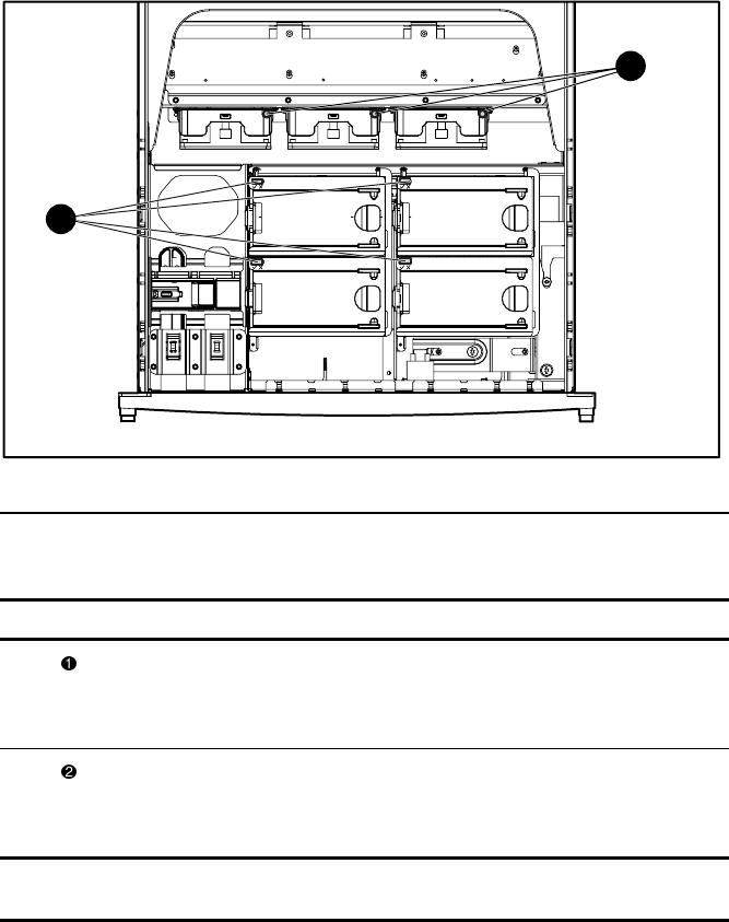
Hot-Plug Fan
The hot-plug fan diagnostic LEDs indicate the condition of each fan in Compaq
ProLiant ML530 servers. If the front panel fan status LED is amber, check the individual fan
diagnostic LEDs to determine which fan has failed.
The hot-plug fan diagnostic LEDs can be viewed by removing the access panel of the server. To
remove the access panel, see “Access Panel” in Chapter 2. Figure 4-7 shows the location of the
hot-plug fan diagnostic LEDs. Table 4-7 identifies the diagnostic LED and describes the
condition of the fan.
To replace a fan, see “Fans” in Chapter 2. The color of the status and diagnostic LEDs resets
when the fan is replaced or system power is cycled.
2
1
Figure 4-7. Hot-plug fan diagnostic LED indicators
Table 4-7
Hot-Plug Fan Diagnostic LED Indicators
Item Description Status Condition
System fans Green
Amber
Off
Fan operational
Fan failure—replace fan
No power to fan
Drive fans Green
Amber
Off
Fan operational
Fan failure—replace fan
No power to fan
Note: Fans may continue to spin after a temporary failure occurs. Replace failed fans (amber
diagnostic LED) even if spinning continues.