
ProLiant ML530 Servers Maintenance and Service Guide


Table Of Contents
- Compaq ProLiant ML530 Servers Maintenance and Service Guide
- Notice Page
- Table of Contents
- About This Guide
- Chapter 1: Illustrated Parts List
- Chapter 2: Removal and Replacement Procedures
- Electrostatic Discharge Information
- Symbols on Equipment
- Preparation Procedures
- Tower Model Front Bezel Door
- Rack Mount Bezel
- Access Panel
- Fans
- Removable Media and Mass Storage Devices
- Cable Routing Diagrams
- System Board Tray
- System Board Components
- Hot Plug Power Supplies
- Power Backplane Board
- Power On/Standby Switch
- Chapter 3: Diagnostics and Troubleshooting
- Diagnostic Tools Utility Overview
- Default Configuration
- Utilities Access
- Power On Self Test
- Diagnostics Software
- Steps for Diagnostics
- 100–199, Primary Processor Test Error Codes
- 200–299, Memory Test Error Codes
- 300–399, Keyboard Test Error Codes
- 400–499, Parallel Printer Test Error Codes
- 500–599, Video Display Unit Test Error Codes
- 600–699, Diskette Drive Test Error Codes
- 800–899, Video Board Test Error Codes
- 1100–1199, Serial Test Error Codes
- 1200–1299, Modem Communications Test Error Codes
- 1700–1799, Hard Drive Test Error Codes
- 1900–1999, Tape Drive Test Error Codes
- 2400–2499, Advanced VGA Board Test Error Codes
- 6000–6099, Compaq NIC Boards Test Error Codes
- 6500–6599, SCSI Hard Drive Test Error Codes
- 6700–6799, SCSI Tape Drive Test Error Codes
- 8600–8699, Pointing Device Interface Test Error Codes
- Array Diagnostic Utility
- Integrated Management Log
- Rapid Error Recovery
- Remote Service Features
- ROMPaq Error Recovery Options
- Compaq Insight Manager
- Chapter 4: Connectors, Switches, Jumpers, and LED Indicators
- Chapter 5: Physical and Operating Specifications
- Index
2-18 Compaq ProLiant ML530 Servers Maintenance and Service Guide
Drive Fan Cable and Cable Bracket
WARNING: To reduce the risk of personal injury or damage to the equipment, the installation
of options other than hot-plug power devices should be performed only by individuals who are
qualified in servicing computer equipment and trained to deal with products capable of
producing hazardous energy levels.
To remove the drive fan cable and cable bracket:
1. Perform the preparation procedures. See “Powering Down the Server” earlier in this
chapter.
2. Remove the hot-plug drive fans. See “Hot-Plug Drive Fans” earlier in this section.
3. Remove the hard drive fan air baffle. See “Hard Drive Fan Air Baffle” earlier in this
section.
4. Remove the hot-plug SCSI hard drives and hard drive cage. See “Hard Drive Cage with
Backplane Board” later in this chapter.
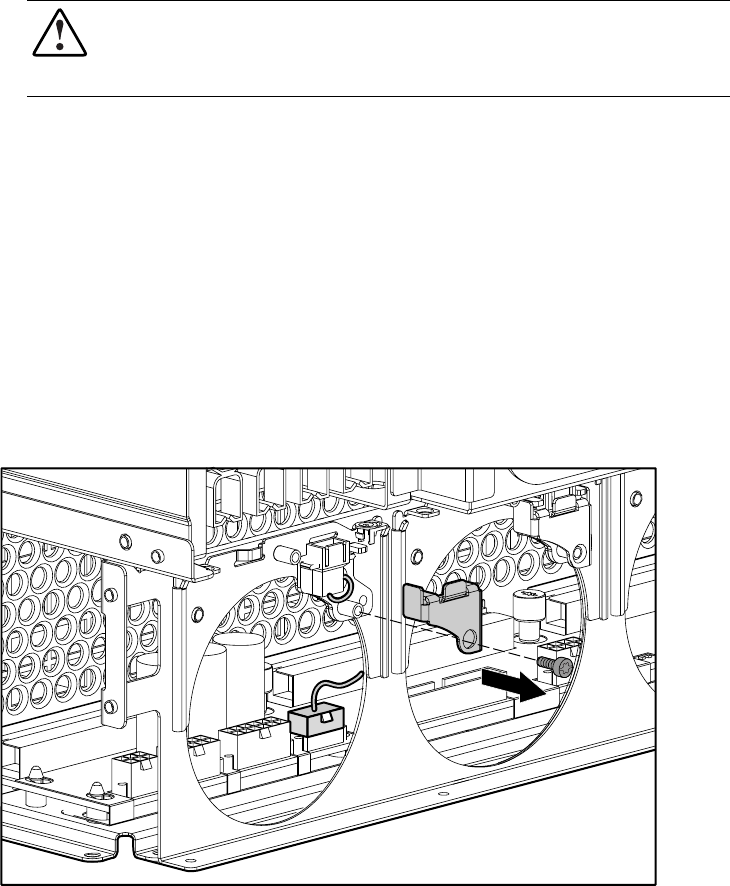
5. Remove the T-10 screw securing the drive fan cable bracket in place, then lift the drive
fan cable bracket from the chassis.
6. Unplug the drive fan cable from the power backplane board and remove it from the unit.
Figure 2-11. Removing the drive fan cable and cable bracket
Reverse steps 1 through 6 to replace the drive fan cable and cable bracket.